

Page 1
PRIMUX
®
Series
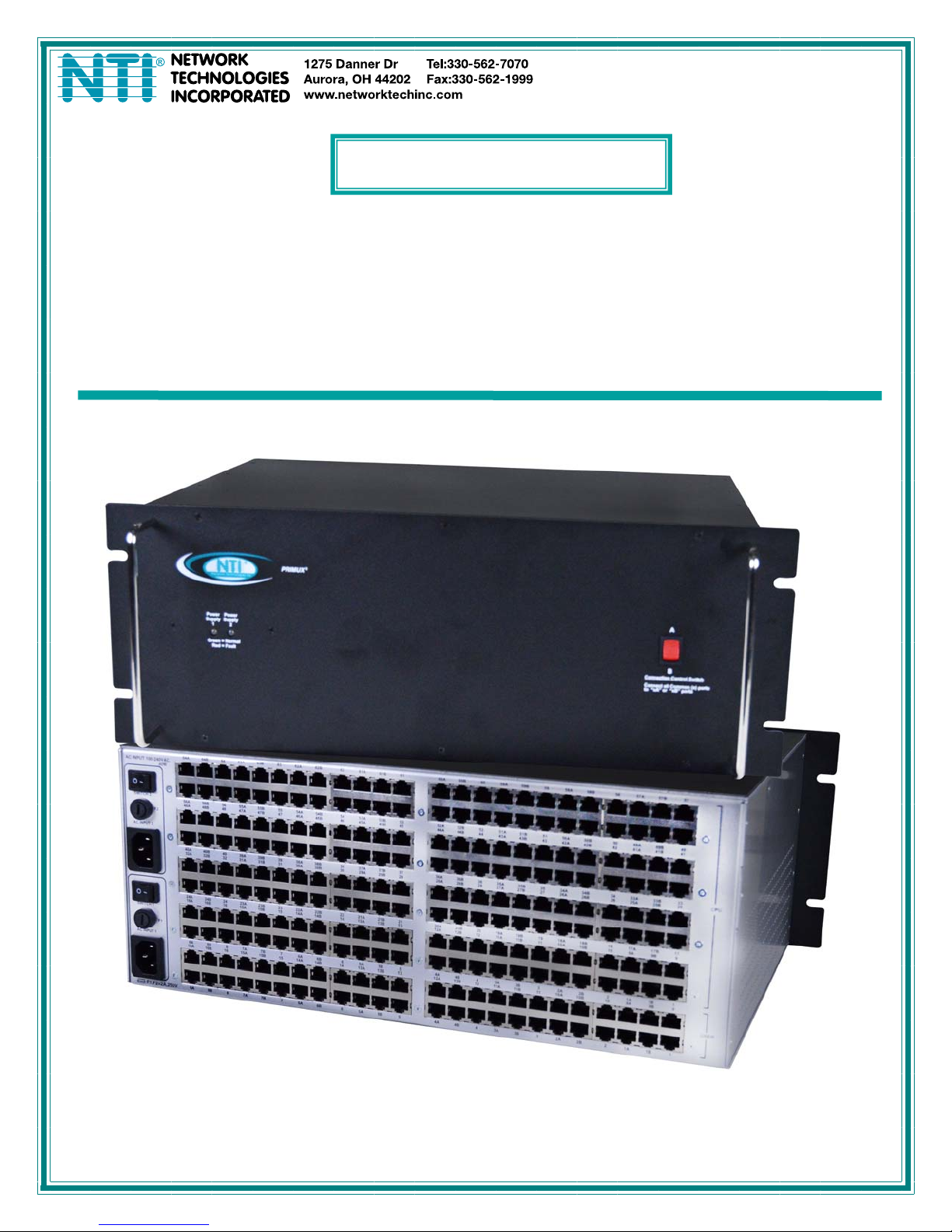
PRIMUX-RDSW
PRIMUX Redundancy Switch
Installation and Operation Manual
MAN202 Rev Date 05/13/2013
Page 2

TRADEMARK
PRIMUX is a registered trademark of Network Technologies Inc in the U.S. and other countries.
COPYRIGHT
Copyright © 2013 by Network Technologies Inc. All rights reserved. No part of this publication may be reproduced, stored in a
retrieval system, or transmitted, in any form or by any means, electronic, mechanical, photocopying, recording, or otherwise,
without the prior written consent of Network Technologies Inc, 1275 Danner Drive, Aurora, Ohio 44202.
CHANGES
The material in this guide is for information only and is subject to change without notice. Network Technologies Inc reserves the
right to make changes in the product design without reservation and without notification to its users.
WARRANTY
The warranty period on this product (parts and labor) is two (2) years from the date of purchase. Please contact Network
Technologies Inc at (800) 742-8324 (800-RGB-TECH) or (330) 562-7070 or visit our website at http://www.networktechinc.com
for information regarding repairs and/or returns. A return authorization number is required for all repairs/returns.
Page 3

TABLE OF CONTENTS
Introduction......................................................................................................................................................................1
Materials..........................................................................................................................................................................2
Connectors and LEDs.....................................................................................................................................................3
Connections.....................................................................................................................................................................4
Connect User Stations.................................................................................................................................................4
Connect Host Adapters................................................................................................................................................5
Connect Power............................................................................................................................................................6
Power Up Sequence.................................................................................................................................................6
Power LEDs.....................................................................................................................................................................7
Connection Control Switch..............................................................................................................................................7
Technical Specifications..................................................................................................................................................8
Interconnection Cable wiring Method..............................................................................................................................8
TABLE OF FIGURES
Figure 1- Connect User Stations........................................................................................................................................................4
Figure 2- Connect Host Adapters (CPUs)..........................................................................................................................................5
Figure 3- Connect Power Cords ........................................................................................................................................................6
Figure 4- Power LEDs........................................................................................................................................................................7
Figure 5- Connection Control Switch .................................................................................................................................................7
Figure 6- View looking into RJ45 female............................................................................................................................................8
Page 4
NTI PRIMUX Redundancy Switch
INTRODUCTION
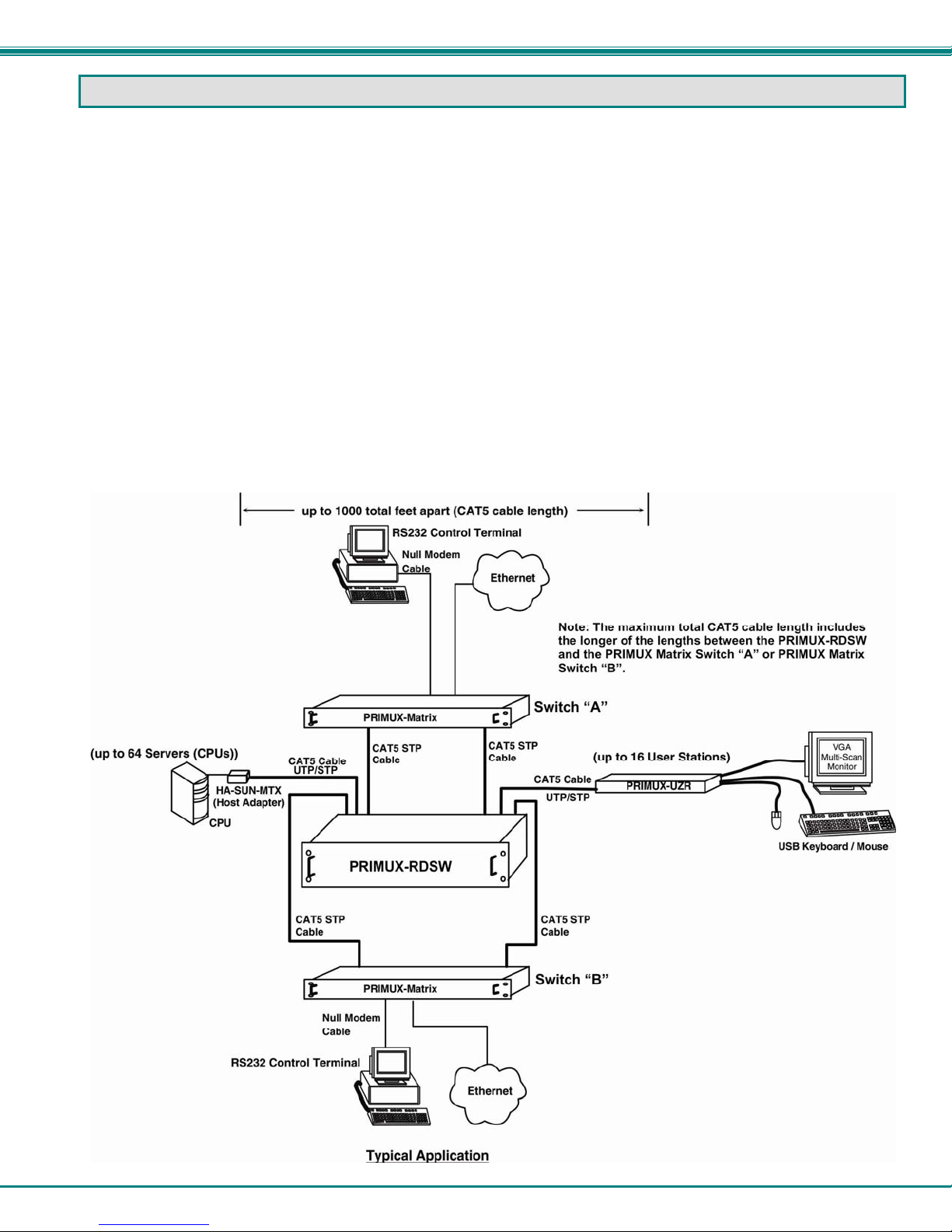
The PRIMUX® Redundancy Switch allows the user to quickly switch over all User Station and Server connections to a back-up
PRIMUX VGA KVM Matrix Switch if the main unit needs to be taken down for service. The position of a rocker switch determines
which matrix switch is used.
The PRIMUX-RDSW provides instantaneous restoration of connections between users and CPUs connected to a PRIMUX KVM
Matrix Switch via CAT5. When used in conjunction with a second PRIMUX Matrix switch, the first switch can be switched to
instantly with the toggle of a switch on the PRIMUX-RDSW.
The PRIMUX-RDSW serves as a recovery switch connecting up to 16 users (connected through PRIMUX-UZR User Stations) to
up to 64 servers (connected through PRIMUX Host Adapters HA-UNV, HA-SUN and/or HA-RS).
• Quickly switch control of User Stations and Servers to the back-up PRIMUX VGA KVM Matrix Switch via CAT5.
• Dual redundant power for reliability.
• Simply flip rocker switch to use back-up unit.
• Supports PRIMUX-8X32, PRIMUX-16X64, and all connected User Stations and Servers.
• Easy cable connections
◦ Use CAT5e STP cables to connect the PRIMUX Matrix Switch to the Redundancy Switch (not included).
◦ Use CAT5/5e/6 STP/UTP cables to connect Host Adapters and User Stations to the Redundancy Switch (not
included).
◦ Up to 1000 total feet of CATx cable can separate the Host Adapters from the User Stations (including the longest
length of cable between the PRIMUX Redundancy Switch and either of the PRIMUX Matrix Switches)
1
Page 5

NTI PRIMUX Redundancy Switch
MATERIALS
Materials supplied with this kit:
• NTI PRIMUX-RDSW Redundancy Switch
• 2-Line cords, country specific
• 4 Cage nuts and 4- #10-32 x ¾” Screws (mounting hardware)
• This manual
Materials Not supplied but REQUIRED:
• PRIMUX Matrix Switches
• PRIMUX-UZR User Stations
• NTI HA-UNV PS/2 + USB Host Adapter / HA-SUN Legacy SUN Host Adapter / HA-RS-M Serial Host Adapter
• CAT5/5e/6 shielded twisted-pair cable(s) terminated with RJ45 connectors wired straight thru- pin 1 to pin 1, etc. (see pg. 8
for proper EIA/TIA 568B wiring method)
• CAT5/5e/6 unshielded twisted-pair cable(s) terminated with RJ45 connectors wired straight thru- pin 1 to pin 1, etc. (see pg.
8 for proper EIA/TIA 568B wiring method)
Cables can be purchased from Network Technologies Inc by calling (800) 742-8324 (800-RGB-TECH) in the US and Canada or
(330) 562-7070 (worldwide).
2
Page 6

NTI PRIMUX Redundancy Switch
CONNECTORS AND LEDS
#
LABEL CONNECTOR/LED DESCRIPTION
1 Power Supply 1 / 2
2 Connection Control
Switch
3 Switch x (x = 1 or 2)
4 F1 / F2
5 AC Input x (x = 1 or 2)
6 CPU
7 USER
Multi-color LEDs illuminates green to indicate proper power to the unit and normal
operation
illuminates red to indicate an internal power circuit failure
Rocker Switch used to provide the switch between connections to Matrix Switch “A”
and Matrix Switch “B”.
Rocker Switch used to switch power On/Off from the power source
Fuse Holder for replaceable overcurrent 2A 240VAC Fast-blo protection fuse
IEC Connector for attachment of power cord
RJ45 Connectors for attachment of CATx cables to CPUs (x), “CPU” ports on
PRIMUX-Matrix switch “A” (xA), and “CPU” ports on PRIMUX-Matrix
switch “B” (xB)
RJ45 Connectors for attachment of CATx cables to PRIMUX-UZR User Stations (x),
“USER” ports on PRIMUX-Matrix switch “A” (xA), and “USER” ports
on PRIMUX-Matrix switch “B” (xB)
3
Page 7

NTI PRIMUX Redundancy Switch
CONNECTIONS
Connect User Stations
Connect a CATx cable from a PRIMUX-UZR User Station to a numbered “USER” port on the PRIMUX-RDSW. Connect only to a
port that does NOT include an A or B (1A, 1B, 2A, 2B).
Connect a CATx cable from a numbered “USER” port on the first PRIMUX-Matrix switch to the same number USER port on the
PRIMUX-RDSW with an “A” added (1A, 2A, 3A, etc). This will be PRIMUX Matrix Switch “A”.
Note: For best performance, use CAT5e STP cables to connect the PRIMUX Matrix Switch to the PRIMUX Redundancy
Switch
Connect a CATx cable from a numbered “USER” port on the second PRIMUX-Matrix switch to the same number USER port on
the PRIMUX-RDSW with a “B” added (1B, 2B, 3B, etc). This will be PRIMUX Matrix Switch “B”.
Repeat these steps for each additional PRIMUX-UZR, up to 16 units.
Figure 1- Connect User Stations
4
Page 8

NTI PRIMUX Redundancy Switch
Connect Host Adapters
Connect a CATx cable from a PRIMUX Host Adapter to a numbered “CPU” port on the PRIMUX-RDSW. Connect only to a port
that does NOT include an A or B (1A, 1B, 2A, 2B).
Connect a CATx cable from a numbered “CPU” port on PRIMUX-Matrix switch “A” to the same number CPU port on the PRIMUXRDSW with an “A” added (1A, 2A, 3A, etc).
Note: For best performance, use CAT5e STP cables to connect the PRIMUX Matrix Switch to the PRIMUX Redundancy
Switch
Connect a CATx cable from a numbered “CPU” port on PRIMUX-Matrix switch “B” to the same number CPU port on the PRIMUXRDSW with a “B” added (1B, 2B, 3B, etc).
Repeat these steps for each additional Host Adapter, up to 64 units.
Figure 2- Connect Host Adapters (CPUs)
5
Page 9

NTI PRIMUX Redundancy Switch
Connect Power
Connect an IEC power cord to an AC power outlet. Optionally, connect a second IEC power cord to a secondary power source.
When both power switches are ON, if the first power source fails, the second power source will automatically take over without
disruption in service.
Figure 3- Connect Power Cords
Power Up Sequence
1. Power ON the monitor(s) connected to each User Station.
2. Power ON each User Station.
3. Power ON the PRIMUX-RDSW.
4. Press the Connection Control Switch on the PRIMUX-RDSW towards the position of the desired connected PRIMUX Matrix
Switch (“A” or “B”).
5. Power ON the selected PRIMUX Matrix Switch.
6. Power ON each CPU connected through a Host Adapter.
For control over the PRIMUX Matrix switch, login to the PRIMUX Matrix switch as described in the PRIMUX Matrix manual.
If a second power source is not connected to the PRIMUX-RDSW, then the corresponding “Power Supply” LED on the front of the
unit will illuminate red and remain illuminated red.
6
Page 10

NTI PRIMUX Redundancy Switch
POWER LEDS
The two power LEDs on the front of the PRIMUX-RDSW are provided to indicate the status of the internal power supplies.
When an LED is green, the associated power supply is functioning normally.
When a single LED is red, the associated power supply has been interrupted. Causes for this include:
• The power switch for that power supply is OFF
• The associated fuse has blown
• The power to the associated AC Input has been interrupted.
When both LEDs are dark, power to both AC inputs has been interrupted.
Figure 4- Power LEDs
CONNECTION CONTROL SWITCH
The Connection Control Switch provides manual control over which PRIMUX Matrix switch is being use d to conn ect all of the
users with the CPUs. When the switch is toggled towards “A”, all users and CPUs are connected through PRIMUX Matrix
Switch “A”. All common port numbers (x) are connected to Switch “A” ports (xA). When the switch is toggled towards “B”,
connections are through PRIMUX Matrix Switch “B”. All common port numbers (x) are connected to Switch “B” ports (xB).
Figure 5- Connection Control Switch
When the Connection Control Switch is used, the Matrix Switch that is now connected to all users and CPUs will automatically
discover all of the connections within the system.
For best performance
Connection Control Switch is used to make connection to it. Power ON the backup Matrix Switch only after the Connection
Control Switch has been set to make connection to it. If the Matrix Switch is already powered ON when the Connection Control
Switch is used to make the connection, the system discovery of all attached components will take longer to occur.
, make sure the backup Matrix Switch (Switch “A” or Switch “B”) is powered-OFF at the time the
7
Page 11

NTI PRIMUX Redundancy Switch
TECHNICAL SPECIFICATIONS
Operating temperature 0°C - 38°C (32°F - 100°F) (17-90% non-condensing RH)
Storage temperature -30°C - 60°C (-20°F-140°F) (17-90% non-condensing RH)
Interconnect cable range Maximum total cable length between User Stations and Host Adapters including the longest length
of cable between the Redundancy Switch and either Matrix Switch must not exceed 1000 feet.
Interconnect Cable- to User
CAT 5/5e/6 Solid UTP/STP EIA/TIA 568 B wiring w/ male RJ45 connectors
Stations / Host Adapters
Interconnect Cable- to
CAT 5/5e/6 Solid STP EIA/TIA 568 B wiring w/ male RJ45 connectors
Matrix Switch
Host Adapter Compatibility HA-UNV, HA-SUN, HA-RS-M
Size (In.) WxDxH 19 x 12.125 x 6.940
Fuse protection 2A 240VAC 5x20 mm Slo-blo
Power requirements 110 or 220VAC @ 50 or 60Hz
INTERCONNECTION CABLE WIRING METHOD
The CAT5 connection cable between all ports and devices is terminated with RJ45 connectors and must be wired according to the
EIA/TIA 568 B industry standard. Wiring is as per the table and drawing below.
Pin Wire Color Pair Function
1 White/Orange 2 T
2 Orange 2 R
3 White/Green 3 T
4 Blue 1 R
5 White/Blue 1 T
6 Green 3 R
7 White/Brown 4 T
8 Brown 4 R
SH Drain wire - Shield
T
1
+
Pair 3
Pair 2 Pair 1
T
R
R
3
2
4
-
+
-
Pair 4
T
5
+
R
R
T
8
6
7
+
-
-
MAN202 Rev.05/13/13
Figure 6- View looking into RJ45 female
8
 Loading...