

Page 1
Page 2

3
NTI Contact Info
NTI AG
Im alten Riet 102
9494 Schaan
Liechtenstein, Europe
Tel.: +423 - 239 6060
Fax: +423 - 239 6089
E-Mail: info@nti-audio.com
Web: www.nti-audio.com
© All rights reserved.
All information subject to change without notice
Version 1.3 / July 2007 / Software 1.10
® MiniLINK, Minilyzer, Digilyzer, Acoustilyzer, Minirator, MiniSPL
and Ministruments are registered trademarks of NTI.
Page 3

Table of contents
1. Minirator Basics ..............................................................4
Introduction....................................................................4
Notes..............................................................................5
Scope of delivery............................................................. 6
Accessories .....................................................................6
2. Overview of the instrument ..........................................7
Connections....................................................................7
Buttons and operating elements......................................8
The screen display...........................................................9
Power supply ................................................................11
Characteristics of the outputs........................................12
3. Getting Started .............................................................14
Inserting the batteries ..................................................14
Fitting the protective shock jacket (MR-PRO only) ..........15
Attaching the hand strap ..............................................16
Connecting the Minirator ............................................. 17
4. Operation ......................................................................18
Switching the Minirator on and off ...............................18
Navigation in the menu bar........................................... 18
Selecting a test signal is easy.........................................19
Setting the parameters.................................................. 20
Setting the sensitivity of the rotary wheel ......................21
System settings ............................................................. 22
Congurations (MR-PRO only)....................................... 23
5. The Minirator test signals ............................................25
Sine ..............................................................................25
Table of contents
Sweep...........................................................................25
Chirp ............................................................................27
Delay Test......................................................................28
Pink Noise.....................................................................29
White Noise ..................................................................30
Polarity..........................................................................30
Wave File Player (MR-PRO only) .....................................31
6. The measurement functions of the MR-PRO ..............34
Display of impedances...................................................34
Balance display..............................................................35
Measuring phantom voltages........................................36
Testing XLR cables (MR-PRO only).................................. 37
7. Updating the instrument..............................................39
General rmware update: ............................................. 39
MR2: Updating the rmware.........................................39
MR-PRO: Updating the rmware...................................39
Calibration....................................................................40
8. Tips and trouble shooting............................................40
Resetting to the factory settings....................................40
Reloading Wave les (MR-PRO only).............................. 40
Faults and their correction............................................. 41
9. Technical data................................................................ 42
10. Further information....................................................44
Warranty conditions...................................................... 44
Declaration of Conformity............................................. 45
Information regarding disposal and recycling.................45
3
Page 4

5
1. Minirator Basics
Introduction
Basics
Thank you for purchasing the Minirator. The Minirator is a powerful audio generator, offering a wide range of analog test signals
for the calibration, maintenance and repair of professional audio
systems.
The rotary settings wheel combined with surrounding fast access
function keys enables instant and intuitive operation without
compromising ne adjustment capabilities.
While the MR2 has been optimized for “Value at a most attractive
price“, the MR-PRO has been developed with additional innovative functionality for even more demanding applications.
4
The MR-PRO is also equipped with the following functions:
• Integrated measurement functions for impedance, balance
and phantom power voltages
• Playback of WAV les
• Cable tester
• High output level
• True Level output stage
• Shock protection
Page 5
Notes
Basics
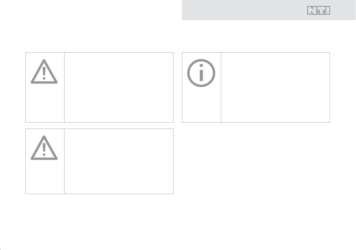
Danger of electric shock
Never connect the instrument to a power
output!
Non-compliance could result in damage to
persons or property that is not covered by
the warranty.
Damage through damp
Do not use the instrument in damp
environments!
The instrument can be permanently
damaged by the penetration of water.
Damage caused by opening the
instrument
Never open the instrument.
The instrument can be damaged if the
housing is opened, and your warranty will be
invalidated.
5
Page 6

7
Basics
Scope of delivery
The following items are included with the respective model:
MR2: • MR2
• Operating manual
• USB cable
• Hand strap
MR-PRO: • MR-PRO
• Protective shock jacket
• Operating manual
• USB cable
• Hand strap
Accessories
Accessories available for the MR2 / MR-PRO:
• Pouch MR2 / MR-PRO NTI Art.No 600 000 302
• System case NTI Art.No 600 000 020
• EU Power Supply 7.5V NTI Art.No 600 000 301
• Cable test plug NTI Art.No 600 000 311
• Calibration certicate NTI Art.No 600 000 303
You can nd more accessories and additional information on the
Internet under www.nti-audio.com
6
Page 7
2. Overview of the instrument
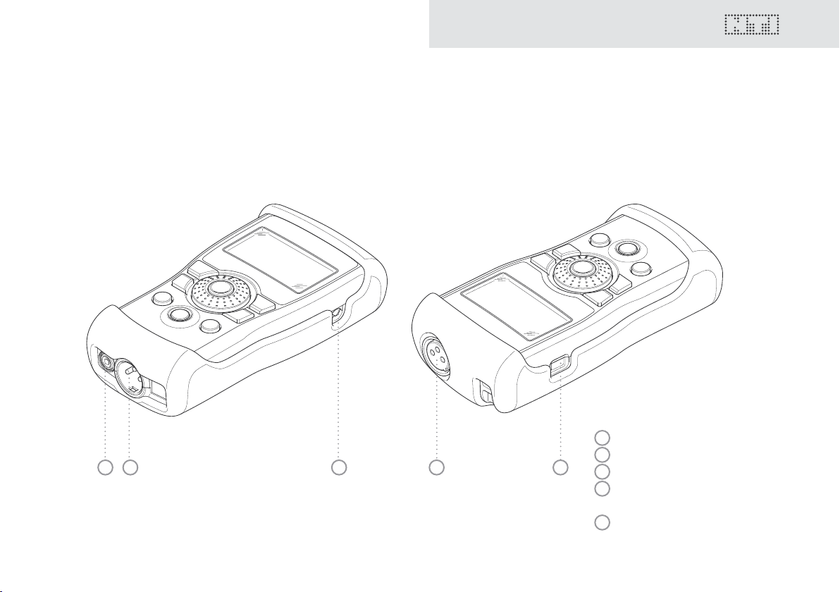
Connections
The Minirator has the following connections:
Overview
1 2 3 4 5
1
RCA output (unbalanced)
2
XLR output (balanced)
3
DC power socket
4
XLR input for the cable test
(MR-PRO only)
5
USB connection (Mini-B, 5 pin)
7
Page 8
9
wave
sens
mute
freq
esc
level
Overview
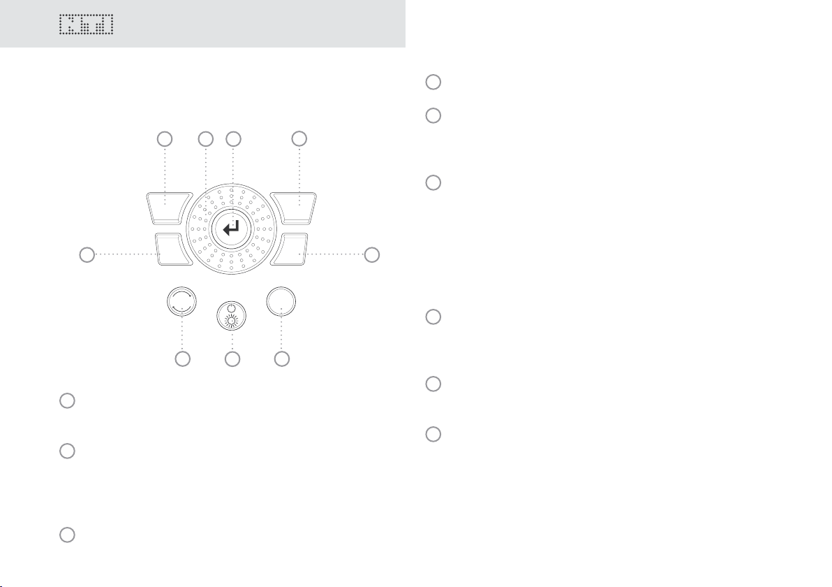
Buttons and operating elements
1 2 3
4
4
Wave Selection of the test signal.
5
Freq Setting the output frequency. Direct jump to
the “PARAM” menu with the “SWEEP” and
“CHIRP” test signals.
6
Mute Switches off the output signal.
Mute is indicated at the lower right corner of
the display.
9
8
1
ESC Terminates an entry and
7
jumps to the top menu level.
2
Rotary
wheel
Slow turning:
Precise setting of the value.
Rapid turning:
Setting the value in larger steps.
3
Enter Conrming a selection.
8
5
The button lights up continually during the
pauses of the “PNoise” and “Chirp” signal
waveforms.
7
On/Off Switches the instrument off if held down for
one second. Switches the back-lighting on
6
8
Sens Changes the sensitivity steps of the frequency
and off.
and level settings.
9
Level Setting the output level. You can set up the
output signal in the following units:
dBV, dBu,V.
With the MR-PRO, dBF (dB referred to Full
Scale) and % units are available when playing
back Wave les.
Page 9
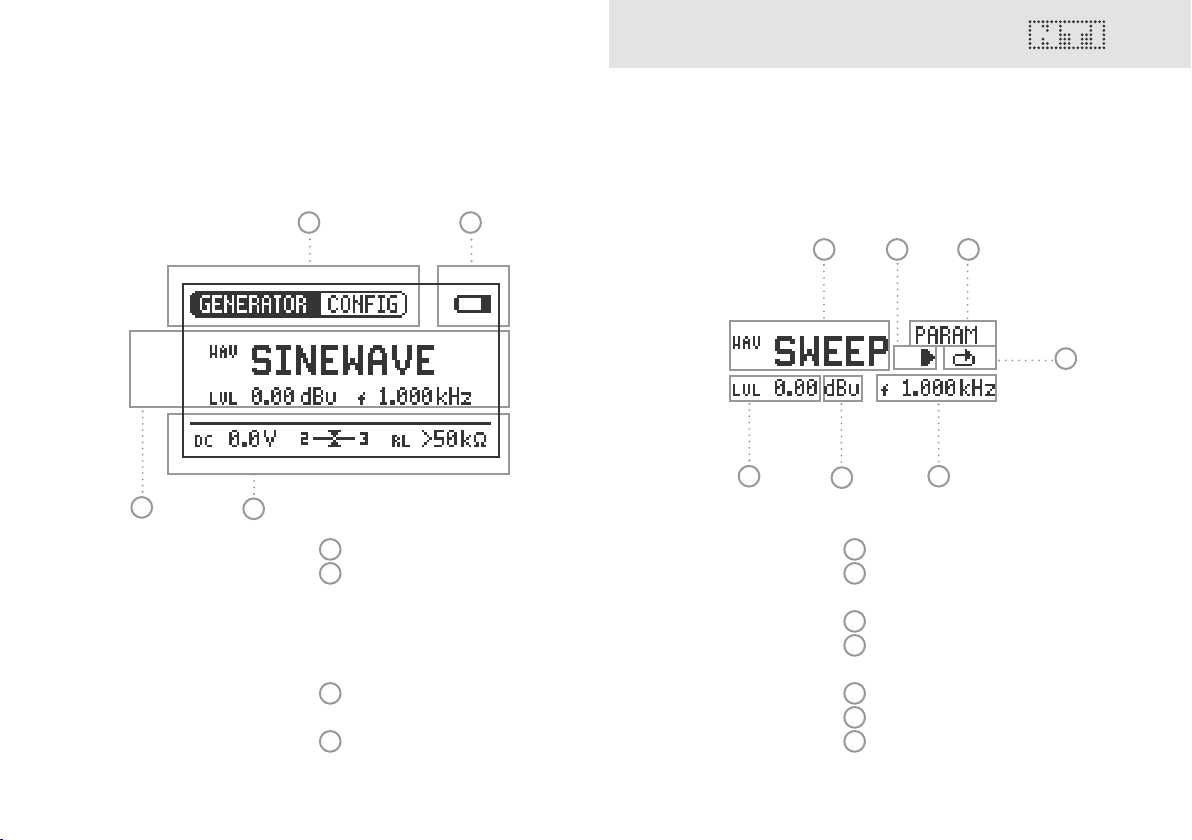
The screen display
Overview
The main menu
4
1 2
3
1
2
3
4
Menu bar
Battery symbol:
If the battery symbol lights
up the batteries are almost
completely discharged and
must be replaced.
Display of the readings
(MR-PRO)
Settings for signal generation
Settings for signal generation
1 2 3
7
6
5
1
Test signal
2
Start / Stop for certain test
signals
3
Setting up the parameters
4
Single / continuous mode for
certain test signals
5
Output frequency
6
Units for the output level
7
Output level
4
9
Page 10
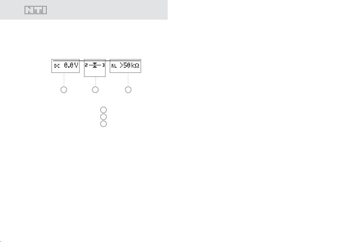
11
Display of the measured values (MR-PRO)
1 2 3
1
Phantom voltage
2
Balance
3
Impedance
Overview
10
Page 11
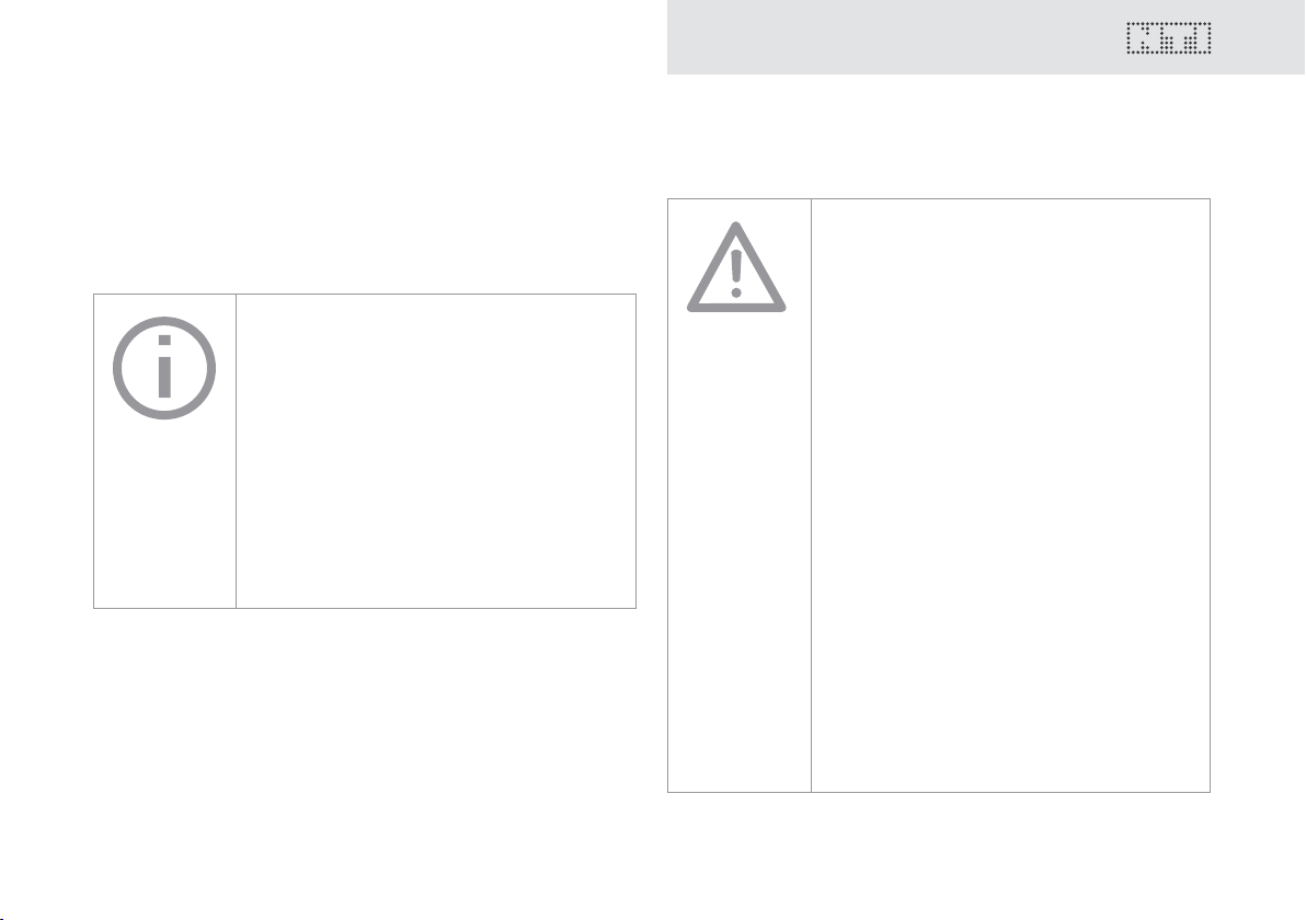
Power supply
Battery operation
In order to be always able to use the Minirator exibly, we recommend the use of batteries.
Only use AA, LR6 batteries.
You will need 3 batteries for battery
operation.
During operation, the battery temperature
may increase noticeably. This is not a defect.
The Minirator can also be used with
rechargeable batteries.
Operation using the mains socket
You can also connect the Minirator to a mains socket with a
DC power supply unit. To do this, you will need the corresponding DC power supply unit, which you can order from NTI.
Overview
We recommend you use only the NTI DC
supply. But if you want to make use of a
different DC power supply unit, you must
observe the following:
Use an electrically-isolated, non-earthed
linear DC power supply unit.
Do not use a switching power supply.
Unbalanced connections in combination
with a switching power supply can lead to
noise interference and an unpleasantly high
interference level when plugging in and out.
Only use DC power supply units with a
voltage from 5 to 8 volts and a current of at
least 500 mA.
Damage caused by using an inappropriate
external DC supply is not covered by
warranty.
11
Page 12
13
2
1
3
XLR
RC
A
~
~
100 Ω
MR2
U/2
U/2
U
100 Ω
0.5 Ω
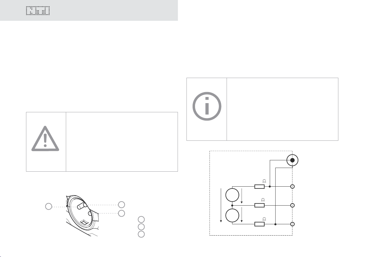
Overview
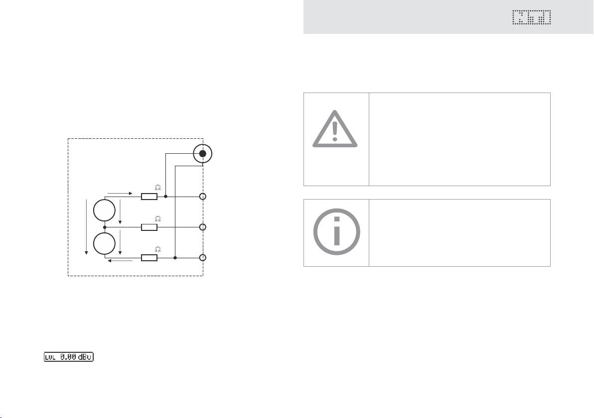
Characteristics of the outputs
The Minirator has two outputs that are wired in parallel:
An unbalanced RCA output and a balanced, non-earthed XLR
output. Both outputs are resistant to externally applied phantom
power.
Wherever possible, always use balanced (XLR) connections, as
these have much better immunity to interference than unbalanced connections.
Do not use both outputs at the same
time.
The simultaneous use of both outputs could
lead to a short-circuit in one of the generator
outputs in the connected instrument.
MR2 outputs
Both the RCA and the XLR have a balanced output impedance
of 200 Ohm.
The voltage at the MR2 XLR or RCA output
is less than the set voltage U with low
impedance loads. Example:
A balanced 200 Ohm load impedance
matching the 200 ohm output impedance will
result in the expected output drop of 6 dB.
Allocation of the XLR output:
2
12
3
1
1
PIN 1
2
PIN 2
3
PIN 3
Page 13
2
1
3
XLR
RC
A
~
~
I<10mA
I<10mA
6.3
Ω
6.3 Ω
MR-PRO
U/2
U/2
U
0.5 Ω
MR-PRO outputs (True Level)
Both the RCA and the XLR have a balanced output impedance of
only 12.5 ohms. The level at the XLR output corresponds to the
set source voltage U (à True Level) over a wide range of loads.
Overview
XLR short-circuit between Pin 1 and 3
Commercially available XLR to RCA adapters
short-circuit the XLR Pins 1 and 3.
Do not use such adapters with the Minirator!
The MR-PRO is designed for loads down to
600 Ohm. Depending on the output level
and the output frequency, however, the True
Level is maintained, even with smaller loads.
Behavior with low-impedance loads
The maximum output current of the MR-PRO is 10 mA. If the
connected load consumes more power, the internal regulation
of the MR-PRO reduces the output level. This condition will be
indicated on the screen by the blinking of the output level display:
13
Page 14
15
3. Getting Started
Getting Started
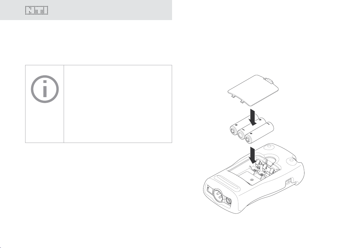
Inserting the batteries
Only use AA, LR6 batteries for the Minirator.
Only use batteries from the same
manufacturer.
Replace the discharged batteries by new
ones.
You can also use rechargeable batteries.
1. Open the battery cover.
2. Insert three AA, LR6 batteries with the same state of charge,
paying attention to the +/- marking in the battery compartment.
3. Close the battery cover once the batteries have been inserted.
C You have now successfully inserted the batteries.
14
Page 15
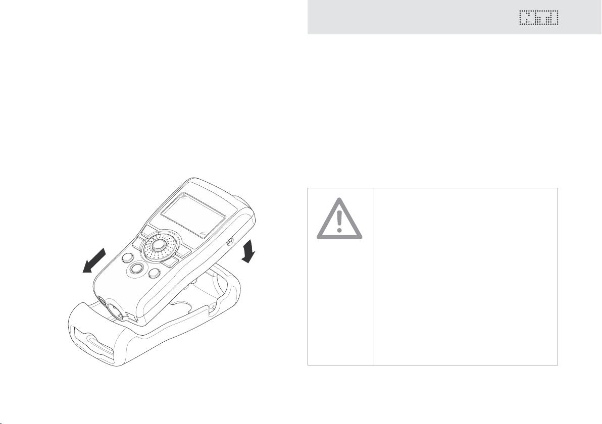
Fitting the protective shock jacket
1.
2.
(MR-PRO only)
With the MR-PRO, you can t the supplied protective shock jacket. This will protect the instrument against light impacts without
impairing its easy operation.
Getting Started
1. Push the lower end of your MR-PRO into the lower end of the
protective shock jacket.
2. Push the upper end of the MR-PRO into the protective housing.
C You have now tted the protective shock jacket
Damage through impacts / shocks
The protective shock jacket shields your MRPRO against reasonable impacts that could
occur in normal use.
But do not intentionally subject the
instrument to extreme stress!
Please do not drop the instrument!
Damage caused by dropping or impact is not
covered by warranty.
15
Page 16

17
2.
1.
3.
Getting Started
Attaching the hand strap
To prevent you from accidentally dropping the Minirator, a hand
strap is supplied with the instrument. You can also t the hand
strap when the protective shock jacket of the MR-PRO has been
tted.
1. Pull the hand strap through the opening.
2. Pull the rear part of the hand strap through the loop of the
front part.
3. Pull the hand strap tight.
C You have now secured the hand strap.
16
Page 17

Connecting the Minirator
Getting Started
XLR connection
1. Connect the Minirator to your audio device using an XLR cable. Note that the locking pin of the plug must be located on
the lower side of the instrument!
C You have now connected the Minirator.
RCA connection
1. Connect the Minirator to the input of the unit to be tested
using a RCA cable.
C You have now connected the Minirator.
17
Page 18

19
4. Operation
Operation
Switching the Minirator on and off
Switching the Minirator on
1. To switch the Minirator on, press the “On/Off” button.
C The display lighting is switched on.
You have switched on the Minirator.
Switching the Minirator off
1. To switch the Minirator off, press the “On/Off” button and
hold it down for one second.
C You have switched off the Minirator.
Navigation in the menu bar
The menu bar is divided into two parts. On the left-hand side, you
can choose between the Generator, Cable test (MR-PRO only)
and System functions.
1. To do this, select the left side of the menu bar with the rotary
wheel and conrm with “Enter”.
C A selection window opens.
2. Select the desired function with the rotary wheel.
3. Conrm the selection with “Enter”.
C You have now selected the desired function.
You can save and call up congurations on the right-hand side of
the menu bar (see the “Congurations” chapter, MR-PRO only).
18
Page 19

Operation
Selecting a test signal is easy
You have two choices for selecting test signals. You can use either
the direct buttons or the rotary wheel.
Signal selection using the direct buttons
1. Ensure that GENERATOR
2. Press the “Wave” button.
C A selection menu appears.
3. Select the desired test signal with the rotary wheel.
4. Press “Enter”.
C You have now selected the test signal.
is selected in the menu bar.
1
Signal selection using the rotary wheel
1. Ensure that GENERATOR
2. Select “WAV”
3. Press “Enter”.
2
1
is selected in the menu bar.
with the rotary wheel.
C A selection menu appears.
1
2
4. Select the desired test signal with the rotary wheel.
5. Press “Enter”.
C You have now selected the test signal.
19
Page 20

21
Operation
Setting the parameters
You have two possibilities for setting up the parameters for the
test signals. You can use either the direct buttons or the rotary
wheel.
Setting parameters using the direct buttons
1. Press the “Level” or “Freq” button.
C You have selected the desired parameter.
2. Turn the rotary wheel to set the parameter.
3. Conrm the setting with the “Enter” button.
C You have now set up the parameter.
Setting parameters using the rotary wheel
1. Turn the rotary wheel.
C The selected parameters will be marked with a black bar.
2. Conrm your choice with the “Enter” button.
C The parameter display blinks.
3. Turn the rotary wheel to set the parameter.
4. Conrm the setting with the “Enter” button.
C You have now set the parameter.
20
Page 21

Setting the sensitivity of the rotary wheel
You can set up the sensitivity (step size) of the rotary wheel. To do
this, proceed as follows:
1. Select Level or Frequency with the rotary wheel.
2. Hold down the “Sens” button.
Operation
C The current sensitivity of the rotary wheel will be displayed
3. Turn the rotary wheel to set up the desired sensitivity.
4. Release the “Sens” button to accept the desired sensitivity.
C You have now changed the sensitivity of the rotary wheel.
1
.
1
21
Page 22

23
System settings
Operation
You can adjust various system settings of your instrument. To do
this, switch to System
and conrm with “Enter”.
The possible system settings are displayed:
1
1
in the menu bar using the rotary wheel
2
3
4
5
Power Save
The Power Save mode switches the instrument off if no button
has been pressed within an adjustable time period.
1. Use the rotary wheel to select the Power Save function
2. Conrm the selection with the “Enter” button.
2
.
C The display starts to blink.
3. Turn the rotary wheel to set the desired time.
4. Conrm the entry with the “Enter” button.
C You have now changed the switch-on time of the Power-Save
mode.
Backlight
Auto:
The backlight will be switched on automatically during operation,
and will be switched off again after a period of time.
Manual:
1. Press the “On/Off” button to switch the background lighting
on and off.
You can choose between “Auto” and “Manual”.
1. To do this, select the Backlight
wheel.
2. Press “Enter”.
3
function with the rotary
C The display now changes between “Auto” and “Manual”.
22
Page 23

Operation
Congurations (MR-PRO only)
Firmware
Display of the version number, with the possibility of carrying
out an update for the MR-PRO
chapter).
4
(see “Update instrument”
Display of the serial number
You can read out the instrument’s serial number
bottom line.
5
from the
Setting the contrast
Changing the contrast of the screen display.
To do this, proceed as follows:
1. Hold down the “ESC” button and turn the rotary wheel until
the desired contrast is obtained.
C You have now changed the contrast of the screen display.
With the MR-PRO, you can store your current instrument settings
as congurations, and can call these up again at a later date.
Storing congurations
10 conguration storage locations are available to you.
1. Using the rotary wheel, select CONFIG in the menu bar.
2. Conrm with “Enter”.
C The following menu is opened:
3. Select STORE and conrm with “Enter”.
C The following selection menu is opened:
23
Page 24

25
Operation
4. Select a memory location with the rotary wheel and store
your conguration by conrming the selection with “Enter”.
C You have now stored the current instrument settings as a
conguration.
Calling up congurations
1. Use the rotary wheel to select CONFIG in the menu bar.
2. Conrm with “Enter”.
C The following menu is opened:
3. Select “Recall” and conrm with “Enter”.
4. Select the desired conguration in the Selection menu and
conrm with “Enter”.
C You have now loaded the desired conguration.
Transferring congurations to another device (MR-PRO)
With the MR-PRO, you have the possibility of transferring stored
congurations to another device.
1. Connect your MR-PRO to a computer via USB.
C A removable memory drive will be indicated on the
computer.
2. Select the CONFIG sub-folder.
C You will see the stored congurations of your MR-PRO.
3. Copy this data to your computer.
4. Connect another MR-PRO to the computer via USB.
5. Copy the previously copied data into the CONFIG sub-folder
by overwriting the data therein.
C You have now transferred congurations from your MR-PRO
to another MR-PRO.
24
Page 25

5. The Minirator test signals
Test signals
Sine
Characteristics and use
Pure sinusoidal signals are required for almost every audio measurement. The Minirator provides a wide and adjustable output
level range and selectable output frequencies.
Parameters
You can dene the following parameters for this test signal:
Output frequency
Output level
Sweep
Characteristics and use
Sweep signals with a resolution of up to 1/12 octave can be
generated over a freely selectable frequency range. An audio
analyzer like the Minilyzer from NTI can automatically trigger to
this signal sequence to measure the frequency response.
Starting the Sweep signal
1. Select the “START” symbol with the rotary wheel.
C You can interrupt a running sweep via the „STOP“
symbol.
25
Page 26

27
B
t
t
TRIG
t
STEP
f
RES
A
ff
f
t
STEPtSTEPtSTEP
f
STOP
f
START
1 kHz
Test signals
Sweep Signal modes
Using the “MODE” symbol, you can run the test signal in the
following modes:
Once-only : Plays the test signal once
Continuous : Repeats the test signal
Parameters:
You can dene the following parameters for this test signal:
Output level
The frequency display is for information only. The current
frequencies will be displayed here once the SWEEP test
signal has been started.
You can congure the signal sequence here.
A The sweep recording starts as soon as the frequency
drops from 1 kHz to fSTART.
B The end of the sweep will be signaled by a falling
frequency.
26
Page 27

Chirp
Characteristics and use
A Chirp is the name for a signal whose frequency continually
changes over time (also known as continuous sweep). It is used
for the recording of frequency responses, the measurement of
impulse responses and the acoustic assessment of rooms.
Starting the Chirp signal
1. Select the START symbol with the rotary wheel.
C If this is activated, it turns into a STOP symbol , which will
end the test signal when selected.
Chirp Signal modes
Using the “MODE” symbol, you can run the test signal in the
following modes:
Test signals
Once-only : Plays the test signal once.
Continuous : Repeats the test signal after an adjustable
pause (tPAUSE).
Parameters
You can dene the following parameters for this test signal:
Output level
The frequency display is purely for information only. The
current frequencies will be displayed here after the start
of the CHIRP test signal.
Conguration of the signal sequence
27
Page 28

29
Fading in and out of any Chirp signal
generates spurious frequency components,
leading to ripple in the frequency response.
The Chirp sequences of the
MR-PRO / MR2 are optimized for ripple of
± 0.2 dB maximum.
Parameter combinations resulting higher
ripple are automatically corrected during
input.
Test signals
Delay Test
Characteristics and use
The Delay Test signal is a specially congured Chirp signal. In
combination with the Acoustilyzer AL1 from NTI, it makes it possible to determine acoustic signal running times. You can nd
further information in the handbook for the AL1 Acoustilyzer.
Parameters
You can dene the following parameters for this test signal:
Output level
28
Page 29

Pink Noise
1
2
Characteristics and use
The Pink Noise test signal has a high spectral density, an innite
period (> 100 years) and 20 kHz bandwidth. Pink Noise is used
as a reference signal for the layout of loudspeaker systems (PA
systems), whereby a Real Time Analyzer (RTA) is used to execute
the required measurements.
When operated in the intermittent mode, Pink Noise forms the
basis for reverberation time measurements.
Test signals
Operation
You can choose between the following test signal modes with
the MOD setting 1:
CONT : generates a continuous test signal.
: generates a intermittent test signal.
You can determine the cycle times of the intermittent signal with
the CYC setting 2.
(3/3 = 3 seconds of signal and 3 seconds pause.)
These settings have no effect in the continuous mode.
Parameters
You can dene the following parameters for this test signal:
Output level
29
Page 30

31
Test signals
White Noise
Characteristics and use
The White Noise test signal has a high spectral density, Gaussian amplitude distribution and an innite period (> 100
years). White Noise is used for all measurements with FFT
analyzers, and has a constant signal power per Hertz and a
20 kHz bandwidth.
Parameters
You can dene the following parameters for this test signal:
Output level
Polarity
Characteristics and use
The sawtooth test signal is ideally suited for checking the polarity
of loudspeakers. The “Minilyzer ML1” and “Acoustilyzer AL1” instruments from NTI detect this signal and determine the polarity.
Parameters
You can dene the following parameters for this test signal:
Output level
The frequency display is for information only.
The frequency cannot be adjusted.
30
Page 31

Wave File Player (MR-PRO only)
1
2
Characteristics and use
You can play back your own test sequences with the MR-PRO.
The test sequences will be repeated automatically and without
pauses.
For a better overview, Wave les are organized in sub-folders.
The MR-PRO is already equipped with a series of demo sequences
in the WAV le format. You can create a link to a computer at any
time via the USB interface and can exchange existing WAV les
or add new ones.
Test signals
Possible applications
Possible applications include, for example:
• Identication generator in the broadcasting sector
• Musical signals for the assessment of PA systems
• Playing back complex test signals
Selecting a folder
1. Select the Symbol folder 1 with the rotary wheel.
2. Conrm with “Enter”.
3. Select the desired folder with the rotary wheel.
4. Conrm with “Enter”.
C You have now changed the current playback folder.
Selecting a Wave le
1. Use the rotary wheel to select the Symbol le 2.
2. Conrm with “Enter”.
3. Select the desired WAV le with the rotary wheel.
4. Conrm with “Enter”.
C The WAV le will be played.
31
Page 32

33
WAVE
FOLDER1 FOLDER2 ...
• Signal1.wav
• Signal2.wav
• ...
• Signal1.wav
• Signal2.wav
• ...
Test signals
Loading your own WAVE les
Wave les for the MR-PRO must fulll the following requirements:
• 48 kHz sampling frequency
• Mono / Stereo
• 16-bit denition
If a Wave le does not meet the
requirements, the playback stops and the
“Mute” button lights up continuously red.
To load WAV-les, you will need a computer
with the following minimum specications:
• PC with Windows 98SE
• Macintosh computer with OSX
1. Connect the MR-PRO to the computer via USB.
C The MR-PRO appears on your computer as a removable data
32
medium.
2. Open the “WAVE” sub-folder on the removable medium
All the sub-folders in the “Wave” folder
now appear in the folder selection . Add
additional sub-folders to this folder level as
required.
1
Page 33

Test signals
3. Open one of the sub-folders in the “WAVE” folder.
If necessary, you can make use of the other
standard possibilities of a removable data
medium. For example, you can copy WAV
les from the MR-PRO onto your computer
or delete unnecessary les.
4. Copy the desired les into the folder.
C You have now loaded your Wave les.
Copyright
NTI delivers a set of demonstration wave les
with the MR-PRO. These wave les may only
be replayed with an NTI unit (MR-PRO). Any
further usage is forbidden.
Parameters
You can dene the following parameters for this test signal:
Output level
The output level of this test signal is adjusted in
dBF (dB full scale) or %.
The absolute level generated at the output
depends on the modulation as well as the
signal form of the data present in the WAV
le.
Example: A fully modulated sinusoidal signal
played back at 0 dBF generates an absolute
level of 18 dBu at the output.
33
Page 34

35
Meas. functions (MR-PRO only)
2
1
3
R2
R3
XLR
RCA
6. The measurement functions of the MR-PRO
The MR-PRO measures phantom voltages and displays impedances and the impedance balance in the SINEWAVE operating mode.
MR-PRO
Display of impedances
Using the SINEWAVE sinusoidal test signal, the MR-PRO measures the load connected to the output between PIN 2 and 3
(RL=R2+R3). The measured values of R2 and R3 will be displayed
by selecting RL with the rotary wheel.
If only R2 or R3 can be measured, RL is replaced by R2 or R3 accordingly.
In the case of balanced connections (XLR),
interference radiated onto the receiver side
will be eliminated.
For this to work there must be a balanced
impedance distribution on both signal
lines. In the case of unbalanced impedance
distribution, signal interference could occur.
The MR-PRO allows you to test the
connections for balance.
34
The impedance and balance measurement
can only be carried out down to a dened
minimum level. If the measurement cannot be
carried out, the display shows:
Page 35

Balance display
The balance display allows localizing a number of typical faults,
such as short-circuits and defective cables.
In the case of an unbalanced impedance distribution, the display
arrow points to the pin with the higher impedance.
Balanced impedance, R2 = R3
Unbalanced impedance, R3 > R2
Unbalanced load relationships can be analyzed further by selecting the impedance display with the rotary wheel. If the impedance cannot be measured, the display shows “---” instead of the
measurement value.
Meas. functions (MR-PRO only)
35
Page 36

37
Meas. functions (MR-PRO only)
2 x 6.8k
V2
V3
2
1
3
+48V
R2
R3
XLR
Measuring phantom voltages
The phantom voltage is necessary in connection with capacitor
microphones in order to operate the impedance converter located in the microphone as well as for some “active” direct boxes.
MR-PRO
Mixing desk
The most common phantom voltage is 48 V and lies on both
Pin 2 and Pin 3 with balanced impedances (see diagram).
36
1
Unequal phantom voltages on Pin2 and Pin3 of the XLR cable
indicate an error and will be displayed by the blinking of the
phantom voltage display (DC).
You can localize the faulty voltage source by selecting the DC
function
1
with the rotary wheel.
Page 37

Testing XLR cables (MR-PRO only)
2
1
3
R2 = 1k
R3 = 2k
XLR
Cable
Out
XLR
In
1.
2.
Meas. functions (MR-PRO only)
The MR-PRO supports a cable test function that quickly detects
damaged cables.
The cable test is based on an impedance measurement. In order
to indicate a correct XLR cable, the test routine of the MR-PRO
assumes the following impedances on the output:
MR-PRO
MR-PRO or adapter
To test a cable, proceed as follows:
1. Select the “Cable test” function in the menu.
2. Plug the XLR cable into the XLR output (1).
3. Plug the other end into the XLR input (2).
37
Page 38

39
Meas. functions (MR-PRO only)
C The following is displayed on the screen:
The cable has not been
plugged in correctly. Check
the cable connection.
The tested cable is defective.
The tested cable is OK.
For long cables already in place, NTI has an
optional adapter. Plug one end of the cable
into the adapter and the other end of the
cable into the MR-PRO. The adapter can be
obtained from NTI as an accessory: Cable
Test Plug, NTI Art.No 600 000 311.
You can nd further information on the
Internet under http://www.nti-audio.com.
38
Page 39

7. Updating the instrument
Updating the instrument
General rmware update:
The rmware is the software of the instrument. Updating is possible by connecting your Minirator to a computer via USB.
You can nd the rmware version of your instrument as follows:
1. Select “System” in the menu bar.
2. Conrm the selection with the “Enter” button.
C The rmware version of the instrument will be displayed.
In order to update the rmware, you
will need a computer with the following
minimum specications:
• PC with Microsoft Windows 2000
• USB termination
You can nd information about the latest available rmware and
the procedure for the update under
http://support.nti-audio.com/mr2
MR2: Updating the rmware
Proceed as follows to update the rmware:
1. Connect your MR2 to the USB connector of a PC and follow
the instructions on the screen of the MR2.
C You have now updated the rmware of your MR2.
MR-PRO: Updating the rmware
Proceed as follows to update the rmware:
1. Select “System” in the menu bar.
2. Click on Firmware and follow the instructions on the screen of
the MR-PRO.
C You have now updated your MR-PRO.
39
Page 40

41
Trouble shooting
8. Tips and trouble shooting
Calibration
The Minirator has been carefully tested during production and
corresponds to the specications listed in the “Technical Data”
chapter.
NTI recommends regular calibration of the instrument in annual
intervals. Please contact your dealer for information regarding
calibration or contact NTI directly on the E-Mail address info@ntiaudio.com
Resetting to the factory settings
If the Minirator reacts unexpectedly, a reset to the factory settings
might solve the problem.
1. Switch the instrument off.
2. Hold down the “ESC” button and simultaneously operate
the “On/Off” button.
C The conrmation of the reset is displayed on the screen.
Reloading Wave les (MR-PRO only)
You can reload the Wave les of the MR-PRO that were installed
in the factory.
The les are available on the Internet. Please visit
http://support.nti-audio.com/mr2 for further details.
40
Page 41

Trouble shooting
Faults and their correction
Fault Fault nding Cause Remedy
The MR2 does not generate
an output signal.
Screen contrast poor. Contrast needs to be
MR-PRO: Wave les are not
played back
MR-PRO indicates no
impedance.
“Mute” button blinks. You have switched the
instrument to Mute.
“Mute” button lights up
continuously.
“Mute” button lights up
continuously.
The lowest line is not
displayed.
You have called up the “Pink
Noise” (PNoise) test signal or
you are in the Pause cycle of
the Chirp test signal.
Cable not plugged in correctly.
adjusted.
Non-supported Wave format. Load a supported Wave
Output level too low.
Incorrect test signal.
Press the “Mute” button.
Wait until the pause has
ended.
Press the “Start” button.
Plug in the cable correctly.
Press “ESC” and operate the
rotary switch to set the
contrast.
format.
Increase the output level.
Change to the SINEWAVE test
signal.
41
Page 42

43
Technical data
9. Technical data
MR2 MR-PRO
Outputs Balanced XLR, unbalanced RCA
Inputs DC power supply, USB DC power supply, USB
Signal wave forms Sine, Pink Noise, White Noise
Wave File Format Sampling freq.:
Frequency setting Range:
Stepped Sweep Function Freq. range:
Continuous Sweep (Chirp) Function Freq. range:
Level Units dBu, dBV, V dBu, dBV, V, dBFS, %
Output Level Ranges Sine, Sweep, Chirp
Flatness RL ≥ 600 Ohm ± 0.5 dB ± 0.2 dB
Accuracy @ 1kHz ± 0.5 dB ± 0.2 dB
Resolution:
Output level:
Increment:
Accuracy:
Increment:
Sweep speed:
Increment:
Chirp speed:
White Noise
Pink Noise
Polarity, Delay Test
-80 dBu to + 8 dBu
-80 dBu to + 0 dBu
-80 dBu to - 2 dBu
-80 dBu to +6 dBu
phantom power resistant
XLR for cable test
Polarity test signal, Delay test signal
48 kHz
16 Bit, Mono / Stereo
0 dBFS = 18 dBu (sine)
according to EBU R68
10 Hz - 20 kHz
in 1 digit steps
0.01%
freely selectable
1/1, 1/3, 1/6, 1/12 octave
selectable 0.5 - 5 seconds
freely selectable
Linear / Logarithmic
0.5 - 20 seconds per cycle
- 80 dBu to +18 dBu
- 80 dBu to +10 dBu
- 80 dBu to + 8 dBu
- 80 dBu to +16 dBu
42
Page 43

Technical data
MR2 MR-PRO
THD+N 22 Hz - 22 kHz, average,
@ 1 kHz, typical
Output impedance 200 Ohm (balanced) 12.5 Ohm balanced, Imax = 10 mA
Impedance measurement Method:
Meas. range:
Accuracy:
Phantom voltage Meas. range:
Accuracy:
USB functionality Firmware update Firmware update
Flash memory 32 MByte for storing wave les and
Display Graphical, with back light
Auto-Power-Off 10, 30, 60 minutes or OFF
Batteries 3 x AA Alkaline dry cells or rechargeable equivalents
Battery Life 0 dBu, no load, typ. 20 hours 10 hours
Temperatue range 0° to 45° C (32° to 113° F)
Humidity < 90% rel. humidity, non-condensing
Dimensions (LxWxH) 147 x 74 x 41 mm 152 x 81 x 43 mm
Weight including batteries 250 g (9 oz.) 310 g (11 oz.)
-90 dB (0.0032%) @ 8 dBu,
Noise oor < 25 μV
-96 dB (0.0016%) @ 18 dBu,
Noise oor < 15 μV
Absolute value Z
4 Ohm - 50 kOhm balanced
2 Ohm - 25 kOhm unbalanced
@ f = 30 Hz to 10 kHz (Sine)
@ Level from -20 to +18 dBu
± 10 % or ± 2 Ohm
0 - 54 V
± 3 % or ± 0.5 V
Mass Storrage Device
congurations
(incl. protective shock jacket)
43
Page 44

45
Further information
10. Further information
Warranty conditions
International warranty
NTI guarantees the function of the MR2 and MR-PRO and their
individual components for a period of one year from the date of
sale. During this period, defective instruments will be repaired
free of charge, or will be replaced.
Limitations
These guarantee provisions do not cover damage caused by accidents, transportation, incorrect use, carelessness, accessories or
the installation of any parts that were not delivered with the instrument, the loss of parts, connection to the mains voltage, operation with non-specied input voltages, adapter types or incorrectly inserted batteries. In particular, NTI accepts no responsibility
for subsequent damage of any kind. The warranty will be voided
by the carrying out of repairs or service work by third parties who
are not part of an approved NTI Service Centre.
44
Repair of the Minirator MR2 / MR-PRO
In the case of faulty functioning or damage, send the instrument
to the local NTI agency in your country in its original packaging.
Please enclose a precise description of the fault. You can nd the
contact addresses on the NTI Internet page www.nti-audio.com
Repair work will only be carried out under warranty upon presenting the original sales receipt.
Page 45

Further information
Declaration of Conformity
CE / FCC Compliance Statement
We, the manufacturer
NTI AG
Im alten Riet 102
9494 Schaan
Liechtenstein, Europe
hereby declare that the Minirator MR2 and Minirator MR-PRO
products, approved in 2007, comply with the following standards
or other standard documents:
EMC: 89/336, 92/31, 93/68
Harmonised standards: EN 61326-1
This declaration will become invalid if modications to the instrument are carried out without the written approval of NTI.
Date: 01.12.2006
Signature:
Information regarding disposal and
recycling
Dispose of your instrument in accordance with the
valid legal environmentally regulations in your country.
Regulations for the European Union and other European
countries with corresponding laws:
The instrument must not be disposed of in the household garbage. At the end of its service life, bring the instrument to a collecting point for electrical recycling in accordance with the legal
regulations.
Other countries outside the EU:
Contact your respective authorities for waste disposal and follow
their regulations.
Position: Technical Director
45
Page 46

For your notes
46
Page 47

Page 48

 Loading...