

Page 1
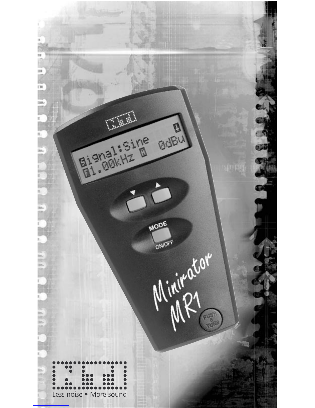
MINIRATOR MR1
Analog Audio Generator
User Manual
Page 2

2
3
NTI CONTACT
NTI AG
Im alten Riet 102
9494 Schaan
Liechtenstein, Europe
Tel. +423 - 239 6060
Fax +423 - 239 6089
E-mail info@nt-instruments.com
Home www.nt-instruments.com
© NTI AG
All rights reserved.
Subject to change without notice.
Release 2.01 / Aug 2005
Minirator & Minstruments are registered trademarks of NTI.
Page 3

3
TABLE OF CONTENT
1. Introduction 4
CE Declaration of Conformity 4
International Warranty & Repair 5
Warnings 6
Overview 7
Test Certicate 7
Battery Replacement 8
2. Basic Operation 9
Getting Started 10
Power On/Off, Low Battery 10
Choose Waveform 12
Change Frequency 13
Change RMS Level 13
Setup Display 14
Connections 15
3. TECHNICAL SPECIFICATION 18
Page 4

4
5
1. INTRODUCTION
Congratulations and thank you for buying NTI’s Minirator
MR1, a product specially suited for professional audio applications. We are convinced you will enjoy using it!
NTI products are manufactured in compliance with the highest quality standards and marked with the CE sign.
In order to avoid any damage to the unit, we strongly recommend to read the entire manual before you start using
the instrument.
CE Declaration of Conformity
We, the manufacturer
NTI AG
Im alten Riet 102
9494 Schaan
Liechtenstein, Europe
hereby declare that the product Minirator MR1, released in
1998, conforms to the following standards or other normative
documents:
EMC-Directives: 89/336, 92/31, 93/68
Harmonized Standards: EN55103-1, EN55103-2
This declaration becomes void in case of any changes on
the product without written authorization by NTI.
Date: 1.4.2000
Signature:
Position of Signatory: CEO
Introduction
Page 5

5
International Warranty & Repair
International Warranty
NTI guarantees the Minirator and its components against
defects in material or workmanship for a period of one year
from the date of original purchase, and agrees to repair or
to replace at its discretion any defective unit at no cost for
either parts or labor during this period.
Restrictions
This warranty does not cover damages caused through accidents, misuse, lack of care, the attachment or installation
of any components that were not provided with the product,
loss of parts, connecting the instrument to a power supply,
input signal voltage or connector type other than specied, or
wrongly polarized batteries. In particular, no responsibility is
granted for special, incidental or consequential damages.
This warranty becomes void if servicing or repairs of the
product are performed by any party other than an authorized
NTI service center or if the instrument has been opened in
a manner other than specied in this manual.
No other warranty, written or verbal, is authorized by NTI.
Except as otherwise stated in this warranty, NTI makes no
representation or warranty of any kind, expressed or implied
in law or in fact, including, without limitation, merchandising or tting for any particular purpose and assumes no
liability, either in tort, strict liability, contract or warranty for
products.
Repair of your Minirator MR1
In case of malfunction, take - or ship prepaid - your NTI
Minirator, packed in the original box, to the authorized NTI
representative in your country. For contact-details please see
the NTI web page www.nt-instruments.com.
Be sure to include a copy of your sales invoice as prove of
purchase date. Transit damages are not covered by this
warranty.
Introduction
Page 6

6
7
Warnings
In order to avoid any problems and damages, follow the
rules listed below:
• Read this manual thoroughly before you operate the
instrument for the rst time.
• Use the instrument for the intended purpose only.
• Never connect the instrument to a voltage output such
as a power amplier, mains power plug, etc.
• Do not disassemble the instrument.
• Never use the instrument in a damp environment.
• Remove the batteries as soon as they are at or if
the instrument is not intended to be used for a longer
period of time.
• Before you connect the Minirator to an input, verify
that level and frequency are in an acceptable range
for the device. Line signals such as guitar inputs may
only be operated to a max. level of 500 mV (-6 dBV),
suitable frequency for a rst test is around 1 kHz.
• If you have headphones or loudspeakers connected,
make sure that the volume control is set to a very low
level to avoid damages to speakers or ears.
• Microphone inputs require low levels of approx.
1 mV only. Make sure that the level is set accordingly
before you connect the Minirator to such inputs.
• Very low and very high frequency signals at high
levels may cause damages to the input of the device
under test.
• High sound pressure levels can cause permanent
damages to your hearing system. Make sure that all
faders of the mixing console are set to minimum to
avoid overloading inputs or giving very loud levels.
Introduction
Page 7

7
Introduction
Overview
The Minirator MR1 is the first member of a family of
miniaturized battery powered audio instruments, called
Minstruments. It is a professional, multifunctional analog
audio signal generator that ts in the palm of your hand.
It covers most of the typical test signals used in a professional
audio environment:
• Sinusoidal Signal, 20 Hz - 20 kHz,
• Frequency Sweep, 20 Hz - 20 kHz
• Square Signal, 20 Hz - 5 kHz
• White Noise
• Pink Noise
• Polarity Test Signal
Over the entire audio band the output level ranges from
the lowest microphone levels in the microvolts range up to
studio reference levels.
The user interface is simple and intuitive with three buttons
only. A short instruction of the Minirator control can also be
found on the rear side of the instrument.
Test Certicate
The Minirator MR1 is fully tested to the manufacturer's
specications. We recommend to calibrate and adjust the
Minirator MR1 in one (1) yearly intervals.
Page 8

8
9
Introduction
Fig 1 Insertion of batteries
Battery Replacement
After unpacking, insert
two batteries into the
battery compartment.
• Hinge out the XLR
connector by pressing the thumb on the
release button. Turn
out the gripped plug
until it locks in the
open position.
• Open the battery compartment ap with your ngernails
or any appropriate tool.
• Insert two 1.5 V AA size alkaline batteries as shown in
Fig 1. The direction is labeled on the rear side of the
instrument.
• Close the battery compartment ap.
Notes • We do not recommend to use NiCd or NiMh
rechargeable batteries.
• Do not insert batteries of different types.
• Note the correct polarities of the inserted
batteries. Wrongly polarized batteries may
cause permanent damages to the electronics
inside!
• Remove the batteries as soon as they are
at.
Page 9

9
Basic Operation
2. BASIC OPERATION
LC Display
Downbutton for
parameter
settings
Up-button
for
parameter
settings
MODE button, push
once to switch on. Press
to toggle to the next parameter. Press and hold for
2 sec to switch off.
Retractable XLR output
connector, balanced.
Push the release button
and turn to fold out. Push
and turn to retract.
RCA (Cinch)
output, unbalanced
Fig 2 Instrument overview
Page 10

10
11
Getting Started
For better understanding, the words MODE, UP and DOWN
refer to the three corresponding keys, whilst the dot matrix
type icons (e.g. (Signal), (Frequency), (Amplitude, Level), ...) refer to the selectable parameters in the display.
Power On/Off, Low Battery
Basic Operation
Fig 3 Power-up screen
Fig 4 Low battery indicator
The MODE-key provides
the on/off functions.
• Press the MODE-key
to switch on.
• The start-up screen appears shortly after showing the
serial number of your Minirator MR1, see Fig 3.
• Hold the MODE-key pressed for about two seconds to
switch the device off again.
Furthermore Minirator features an Auto Power OFF function that automatically switches off the instrument after a
selectable duration of inactivity. Refer to 2.8.a Dene the
Auto Power Off Time.
Notes • Minirator reverts all values to the last active
status when powered on.
• If exposed to very high electrostatic
discharges, the instrument might loose
control (e.g. no display). In such a case,
switch the instrument off and on again.
The Minirator features a low battery status indicator,
displaying the end of the battery lifetime, see below Fig 4.
A pulsing vertical block
becomes visible at the
right top corner of the
display, reminding to
replace the batteries.
Page 11

11
• Each time you press the MODE-key you will move to
the next selectable item. The currently selected item is
indicated by a ashing, inverted rst character. In Fig 7
the letter is selected, represented graphically by gray
color.
• To alter the parameter use the UP- and DOWN-keys.
The changed parameter becomes immediately effective.
The signal setting cycles through the available values
while amplitude and frequency stop at their maximum
and minimum values.
MODE-, UP- and DOWN-key provide a repeat function if
you keep them pressed.
Basic Operation
Display
The display shows either
the signal parameter
screen, Fig 5, or the setup
screen, Fig 6.
In the parameter screen
the waveform, frequency
and level may be altered.
The setup screen allows
the change of setup para-
Fig 5 Default values
Fig 6 Setup display
Fig 7 Selectable items
meters. By selecting the arrow-symbol in the right top corner
and pressing the corresponding arrow-key you may switch
from one to the other screen.
After initialization, the instrument will re-enter the last active
status prior switching off the last time.
To re-enter factory settings, as shown in Fig 5 and Fig 6
switch the Minirator MR1 on with pressing the UP- and
MODE-key simultaneously.
Keypad
The Minirator has only
two basic rules:
Page 12

12
13
Choose Waveform
Select the -sign with the MODE-key and toggle through
the available waveforms using the UP- or DOWN-key. The
available waveforms are listed in below Table 1.
Waveform Frequency Description
Sine 20 Hz -
20 kHz
Pure, low distortion sinusoidal
waveform dened by frequency and
level (RMS) in the display. This is the
most common waveform in the audio
world for measurements of frequency
response, distortion, etc.
Sweep The output signal is sequentially
stepped through all the available
frequencies. Step duration can
be adjusted. Actual frequency is
displayed. Sweep starts automatically
indicated by the rotating bar .
W. Noise White noise signal with 20 kHz band-
width. Use this signal in conjunction
with a spectrum analyzer (FFT
analyzer).
P. Noise Pink Noise signal with 20kHz
bandwidth. Signal level decreases
with 10 dB/decade (3 dB/octave).
Use this waveform in conjunction with
swept narrow band lters for auditive
(aural) testing.
Square 20 Hz -
5 kHz
Square wave signal with 50% duty
cycle and no DC offset.
Pol Test 20 Hz Proprietary polarity test x frequency
of 20Hz.
Basic Operation
Page 13

13
Basic Operation
Change Frequency
The frequency range of the instrument covers the entire
audio range from 20Hz to 20kHz in 31 1/3rd octave steps.
20 Hz 25 Hz 30 Hz 40 Hz 50 Hz 65 Hz 80 Hz 100 Hz
125 Hz 160 Hz 200 Hz 250 Hz 315 Hz 400 Hz 500 Hz 630 Hz
800 Hz 1 kHz 1.25 kHz 1.60 kHz 2.00 kHz 2.5 kHz 3.15 kHz 4.00 kHz
5.00 kHz 6.30 kHz 8.00 kHz 10.0 kHz 12.5 kHz 16.0 kHz 20.0 kHz
Select the -sign with the MODE-key and toggle through
the frequencies using the UP- or DOWN-key.
Note • The frequency may not be altered in
waveforms Sweep, Pink Noise, White Noise
and PolTest.
Change RMS Level
To change the level of the generated signal, toggle with the
MODE-key, until the -character is ashing and increase
or decrease the level with the UP- or DOWN-key.
Waveform Unit Range Increment
Sine, Square,
White Noise,
Sweep
dBu
dBV
Volts
-76 dBu - +6 dBu
-78 dBV - +4 dBV
0.13 mV - 1.6 V
2 dBu
2 dBV
~±23%
Pol Test dBu
dBV
Volts
-76 dBu - +4 dBu
-78 dBV - +2 dBV
0.13 mV - 1.25 V
2 dBu
2 dBV
~±23%
Pink Noise dBu
dBV
Volts
-56 dBu - -4 dBu
-58 dBV - -6 dBV
1.25 mV - 500 mV
2 dBu
2 dBV
~±23%
Table 3 Level ranges and increments for signals and units
Table 2 Frequency table for sinusoidal signals
Page 14

14
15
• To revert to the signal parameter screen, select the sign and press the UP-key.
a. Dene the Auto Power Off Time
Minirator features an auto power off function, switching the
instrument off after a certain period of no key-press. The
default setting is 10 minutes. To alter the auto power off
time select with the MODE-key the -sign, Pwrsave. The
power off time may be decreased by using the DOWN-key or
increased with the UP-key and is immediately active.
Available settings:
10 minutes [10min], 30 minutes [30min],
60 minutes [60min] and OFF [Off]
In the OFF mode, the instrument remains active until the
batteries are at by not switching off the MR1 manually.
b. Change Level Units
Select the -sign with the MODE-key and toggle through
the available units using the UP- or DOWN-key. The new
unit is immediately active. The default unit is dBu.
Available settings:
Volts [V], logarithmic level dB Volts [dBV],
logarithmic level dB unit [dBu]
• Select the -sign.
• Press the DOWN-key
to reach the setup
screen.
Basic Operation
Setup Display
Fig 8 Setup display
Page 15

15
Basic Operation
c. Change Sweep Speed
In the sweep mode the MR1 automatically sweeps through
the audio band by stepping through all the available 1/3
octave frequencies as per Table 2. The user may dene the
sweep speed by setting the duration of each frequency. To
alter the sweep speed select the -sign with the MODE-key
and toggle through the available settings using the UP- or
DOWN-key.
Available sweep increment settings:
50 milliseconds [50m], 500 milliseconds [.5s],
1 second [1s], 2, 3, 4 and 5 seconds
The new sweep speed is immediately active. At the beginning of each cycle, a 1kHz start tone remains active twice
as long as the step duration dened. A running sweep is
indicated by a rotating bar in top right corner of the signal
parameter screen.
Connections
Minirator features two output connectors, an unbalanced
RCA (Cinch or Phono plug) output and a balanced, groundfree XLR connector. The RCA output is permanently active,
whilst the XLR pins are only connected in the folded out
position.
Note • Never connect both outputs simultaneously,
it may cause short circuits.
a. Balanced / Unbalanced Connections
Use balanced connections via the retractable XLR output
pins whenever a balanced input is available, especially for
low level input signals such as microphone inputs and for
longer cables. Balanced connections have the advantage of
a far better noise and hum immunity.
Unbalanced connections are advised if the input of the
device is unbalanced such as inputs of HiFi ampliers and
low cost mixers.
Page 16

16
17
The XLR output is a balanced signal output with nominal
200 ohm output impedance, see Fig 10. The XLR pins are
retractable in order to protect the pins from inadvertent connections and short circuits. To ip the connector out, push the
release button and turn the XLR output whilst pressing. For
example press a nger into the notch on the rotator, see Fig
11. To retract the pins, simply press again the release button
and turn the pins back.
b. RCA Output
The RCA, also called phono connector or cinch connector, is located
on the top of the instrument, see Fig
9. It provides the selected output
signal in an unbalanced mode with
a nominal output impedance of
200 ohm. The center pin carries
the signal (hot), and the screen
is the ground. The RCA output is
always active regardless of the XLR
connectors position.
c. XLR Output
Fig 9 RCA output
Fig 10 XLR output Fig 11 Open the XLR output
Basic Operation
Page 17

17
The XLR pin
assignment,
see Fig 12, is
internationally
standardized.
Basic Operation
Fig 12 Pin assignment
Pin 2 (gold)
Pin 3 (gold)Pin 1 (silver)
Fig 13 Balanced output diagram
• Pin 1 (silver plated, left hand side) is connected to the
cable screen only and is the reference for pin 2 and pin
3 with balanced loads.
• Pin 2 (gold plated, right hand side) provides the signal
with positive polarity.
• Pin 3 (gold plated, center) provides the signal with negative polarity.
The difference of the signals (pin2-pin3) results in the balanced signal of doubled amplitude, see below Fig 13. Each
of the semi outputs has a source impedance of 100 ohm,
corresponding to 200 ohm in balanced mode.
Page 18

18
3. TECHNICAL SPECIFICATION
Outputs Balanced XLR, unbalanced RCA,
phantom power resistant
Waveforms Sinusoidal, Square, White Noise,
Pink Noise, Polarity
Frequency Range 20 Hz - 20 kHz in 31 steps (Sine)
20 Hz - 5 kHz in 25 steps (Square)
Frequency Sweep 20 Hz ... 20 kHz with sinusoidal signals
Sweep Speed 0.05, 0.5, 1, 2, 3, 4, 5 sec. per step
Units dBu, dBV, V selectable
Level Ranges Waveform Range Inc
Sine, Square -76 dBu to +6 dBu 2 dBu
White Noise -78 dBV to +4 dBV 2 dBV
Sweep 0.13 mV to 1.6 V ±23%
Pol Test -76 dBu to +4 dBu 2 dBu
-78 dBV to +2 dBV 2 dBV
0.13 mV to 1.25 V ±23%
Pink Noise -56 dBu to -4 dBu 2 dBu
-58 dBV to -6 dBV 2 dBV
1.25 mV to 0.5 V ±23%
Flatness ±0.5 dB
Accuracy ±0.5 dB
THD+N <-72 dB (0.025%) typical @ 6 dBu, 1 kHz
<-55 dB (0.18%) or 0.1mV, 20 Hz - 20kHz
White Noise 20 Hz - 20 kHz, Crest factor = 2.12
Pink Noise 20 Hz - 20 kHz, Crest factor = 3.27
Output Impedance 200 ohm balanced & unbalanced
Auto Power Off 10, 30, 60 minutes or OFF
Batteries 2 x 1.5 V Dry or NiCd type cell,
LR 6, AA, AM3 types
Lifetime Typical battery lifetime >20 hours
Temp. Range 0° to +45 °C (32 °F to +113 °F)
Humidity < 90% R.H., non condensing
Dimensions 140 x 74 x 25 mm (5.5" x 2.9" x 1")
Weight 170 g (6 oz) including batteries
Technical Specication
Page 19

Page 20

Quick Guide
Minirator MR1
Select with Select with
MODE
F
MODE
On / Off (2 sec)
 Loading...