

Page 1
MegaDipol
MD300DX
Active Dipole Antenna Amplifier
9kHz - max. 300MHz
Operating Manual
Version V1.2
Issue 06/2018
Manufactured by Rudolf Ille Nachrichtentechnik • www.nti-online.de
Distributed by
Bonito - Dennis Walter • Gerichtsweg 3 • D-29320 Hermannsburg • www.bonito.net
TECHNICAL DATA
Antenna:
Power supply:10 - 15V DC (max. 40mA) via power inserter or 5V supply via USB with
recuced IP-values of 3-5dB and same gain
Connectors and impedance: BNC / 50 Ohms
Radiator connections: M5 screws (stainless steel)
Frequency response (-3dB) and nominal gain:
• 0dB Gain: 9kHz - 300MHz
• 3dB Gain: 9kHz - 130MHz
IP3: typ. +30dBm (@7.00 & 7.20MHz)
IP2: typ. +78dBm (@7.00 & 7.20MHz)
Size / weight: 98 x 90 x 38mm / 0.12kg
DualPower Inserter CPI1000DP:
Power supply max. 15V DC / max. 400mA current-limited and protecteted against
polarity reversal
Connectors: 2.1mm DC power socket (positive inner; alternatively via USB (USB-B port)
Size / weight: 86 x 70 x 29mm / 0.09kg
Scope of delivery:
• MegaDipol MD 300DX
• DualPower Inserter CPI1000DP
• 2x 2.5m long radiating elementc (PVC-coated, salt water resistant stainless steel ropes
• 2x insulators for installation (weatherproof plastic material with 4.5mm fixing hole)
Safety instructions
In case of thunderstorms or overload
Both inputs of the MD 300DX have an input protection circuit against static discharges with ESD protectors up
to 8kV and thus conforming to IEC 61000-4-2 Level 2/max 1ns and an additional 4kV fine protection
Disclaimer - please note
The integrated overvoltage protection circuit will not protect your equipment from a lightning strike in the event
of a direct hit to the house or the vicinity. Irrespective of the radiation element lengths, high voltages can
permanently damage the antenna electronics and/or connected devices. For this reason, liability for these
devices is excluded. Other types of damage caused by overloads or by direct HF-exposure (transmitting
antennas) are also excluded from the warranty.
In case of absence from home, the potential danger of transmitting (ham radio stations), and thunderstorms
etc., can be avoided by disconnecting the antenna cable to avoid any damage.
In the vicinity of strong transmitters, please note also
In the rare case of immediate vicinity (less than 100m) to very strong transmitters, overdrive effects can
occur, which may overload the antenna electronics and/or connected devices. This can happen in the case of
more than -10dBm output level. Weak signals may surpressed and phantom signals can occur.
Since the reception range of the MD 300 X is 300MHz max, signals outside the shortwave spectrum can also
cause such negative effects.
®
NT
i
© 2018 •
Subject to technical modifications; no responsibility is accepted for the accuracy of this information. All descriptions are for
informational purpose only and cannot be understood as express promises concerning the properties of the products or as warranties. All
trademarks acknowledged.
CAUTION:
This is strictly a receive-only antenna. Never
connect it to a transmitter. This would damage
your antenna and would also void your
guarantee. Do not place it directly next to a
transmitting antenna.
Page 2
23456789012345678901234567890121234567890123456789012345678901
2
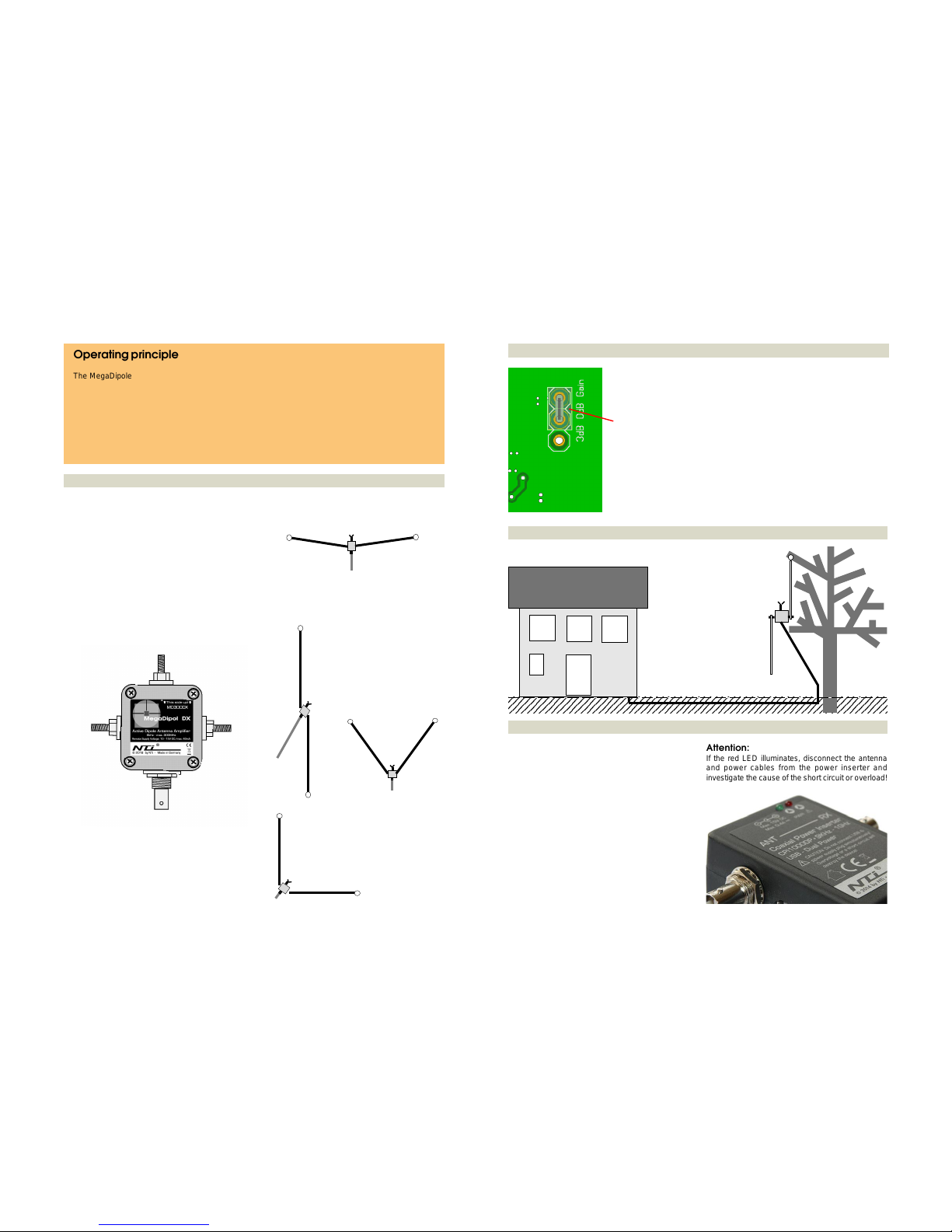
Attention:
If the red LED illuminates, disconnect the antenna
and power cables from the power inserter and
investigate the cause of the short circuit or overload!
Operating principle
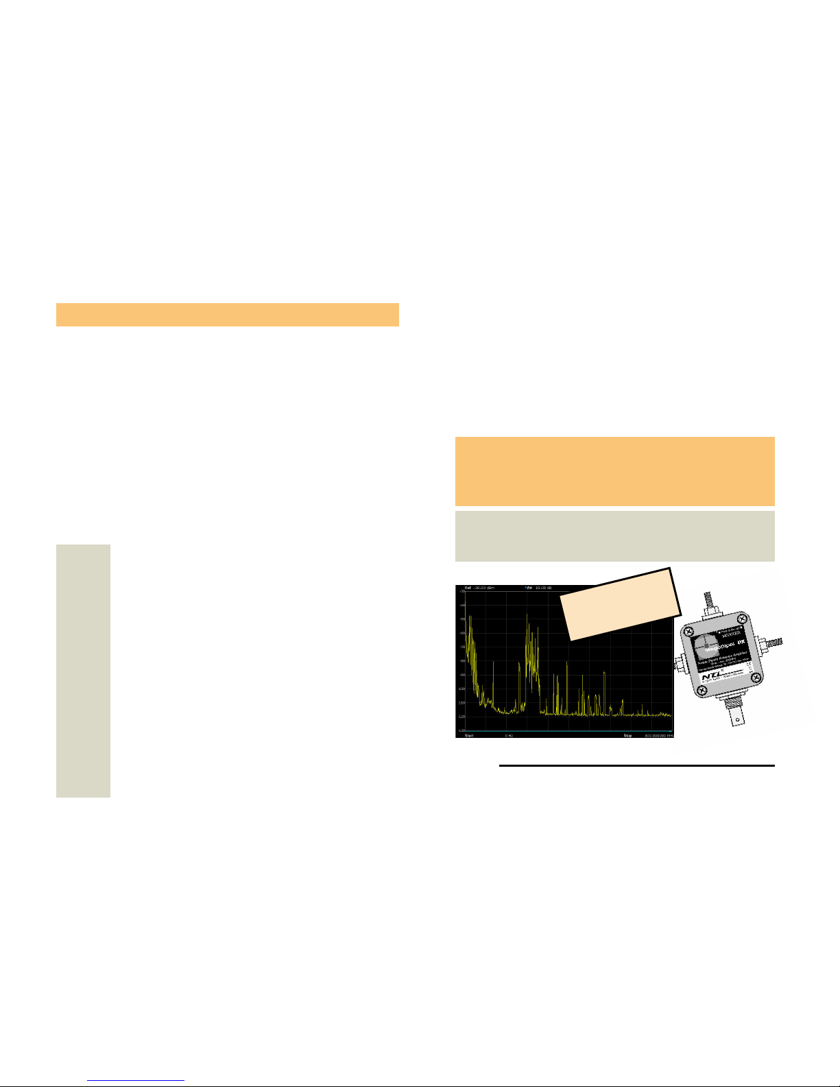
The MegaDipole 300DX is a broadband active dipole with a maximum upper working frequency of 300
MHz. The dipole reacts to the electrical component (E-Field) of the electromagnetic field. The dipole will
deliver best results regarding signal strength and SNR (signal -to-noise-ratio) at locations with little or no
locally generated interference. Nonetheless, the receiver should have a high enough dynamic range so
that it can effectively process the received signals.
In contrast to simple E-field antennas with only one radiating element, the symmetrical construction
of the MegaDipole 300DX, will result in almost no negative resonance effects or reflections caused
by the coaxial cable.
Gain switching 0/3dB
Jumper for gain
selection 0/3dB
Default: 0dB
Example of outdoor-installation
Coaxial power inserter
The antenna electronics are powered via the connected
coaxial cable of the power inserter. Power is supplied
by the power inserter (CPI 1000DP) which can also be
fed by an external power supply. Whenever possible,
do not use a switch mode power supply, it is always
preferable to use a transformer.
Power can also be supplied via USB. Do not use different power supplies simultaneously! A self-resetting
fuse will limit the power input to 400mA in case of a
short circuit. The power inserter has two LED-status
indicators:
Green (PWR): Operating voltage display
Red (!): Short-circuit or overload indicator
Installation examples
Horizontal installation
(Horizontal polarisation; two distinct minima)
Vertical installation
(Vertical polarisation; omnidirectional reception)
Recommended for maximumum performance
V-shaped installation
(Mixed polarization;
predominantly horizontal
component with only weak
minima)
L-shaped intallation
(Mixed polarization with polar pattern: signals opposite
the horizontal leg will be
attenuated)
An inconspicuous
installation for vertically
polarized omnidirectional
reception outside the
electromagnetic noise of
your home.
The coax cable run should
be positioned away from
the lower element and
should not be placed next
to the radiating element.
Within the antenna case, there is a jumper for
selection of optimum gain.
Under normal circumstances the jumper should be
set to 0dB gain.
Only when working with short radiating elements up
to a maxium of 1m in length, is it advisable to
increase the gain.
The gain of the antenna is proportional to the length
of the radiation element; doubling the length of the
radiating element will result in 6dB signal increase.
As a consequence, you should lengthen the radiation
elements before attempting to increase the gain.
>>> radiation element
opt.
grounding
>>> radiation element
Radiation elements
Because of the separation of the antenna electronics
and antenna radiator, the MegaDipol DX offers a flexible solution for connecting different types of radiator
elements.
The standard version consists of two radiating elements
of 2.5m each constructed from stainless steel and seawater resistant PVC-coated high-grade cables.
In principle, it is also possible to connect home-made
radiating elements, however, they should not be longer
than 4m, to avoid overloading in the antenna electronics
or the receiver.
The radiators are fixed to the two M5-screw connectors
on the side of the unit using tooth lock washers and
wing nuts. It is important to install the antenna case with
the BNC-connector pointing downwards because there
are two small holes to allow condensation to exit.
Optional: You may also attach a grounding wire at the
upper connector. The ground is connected internally to
the coax outer conductor (ground BNC-jack).
 Loading...