

Page 1
17,
NETWORK
TECHNOLOGIES
INCORPORATED
1275 Danner Dr
Aurora, OH 44202
Tel:330-562-7070
Fax:330-562-1999
KEEMUX-Sx (SUN KVM Switch)
INSTALLATION / USER GUIDE
MAN061 Rev Date 3/3 0/ 2001
SUN WORKSTATION
SUN WORKSTATION
SUN WORKSTATION
SUN WORKSTATION
NETWORK
17,
KEEMUX-Sx
TECHNOLOGIES
INCORPORATED
2345678
1
SCAN
OFF
ON
MODE
BROAD
CAST
1 2 3 4 5 6 7 8
COM
MAND
TABLE OF CONTENTS
Introduction
Cables
Cables NOT supplied but r equir ed............. .. ............. .. .. .. ................. 2
Installation
Keyboard Configuration
Cascading
Introduction....................................................................................... 3
Limitations......................................................................................... 4
Configuration.....................................................................................4
Cascaded Installat ion........................................................................ 4
Using the NTI Switch
Front Panel Contr ol.. ........................... .. .. .............. ............. .. .. ........... 5
Keyboard Control.............. .. ............. .. .. .. ......................... .. .. .. ............ 5
SCAN MODE
BROADCAST MODE
Keyboard Updating
How To Disable Operating Modes
Technical Speci ficat ions
Troubleshooting
Warranty Informati on
......................................................................................... 2
........................................................................................... 2
..................................................................... 3
........................................................................................ 5
........................................................................... 5
……………………………………………………….. 5
……………………………………… 6
....................................................................10
..................................................................................10
..........................................................................10
SUN WORKSTATION
SUN WORKSTATION
SUN WORKSTATION
SUN WORKSTATION
1
Page 2
INTRODUCTION
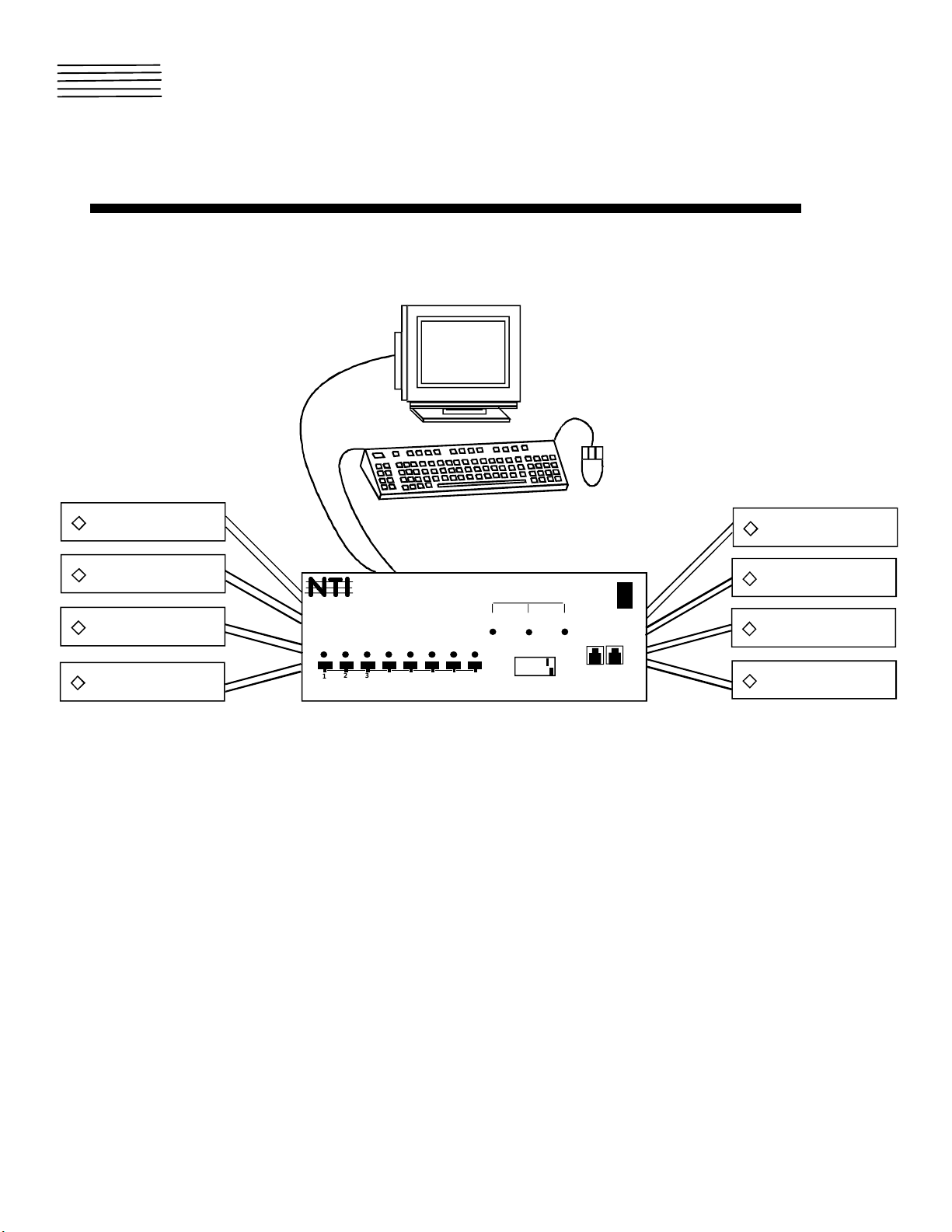
The NTI Sun Switch allows a single keyboard, monitor, and mouse to communicate directly with any Sun workstation connected to
the switch (up to 32 computers with a single switch, depending on the switch model, or 128 computers when cascaded – see
CASCADE section). These computers can be file servers, network managers, etc. The auto-boot circuitry in the NTI Switch
allows all computers to boot simultaneously without keyboard error.
Available Options
1. Switch models are available in 60 or 50 Hz, and 110 or 220V.
2. A hard-wired remote control (RMT) is available. This remote comes
xx
standard with a 25 foot cable (REXT-
), but a cable of up to 250 feet can be ordered.
CABLES
Monitor, keyboard and mouse interface CABLES ARE REQUIRED but not supplied. Before beginning installation, refer to
installation drawing to insure that you have the proper type and number of cables needed.
1. SUCEXT-xx Connects the video port of the computer to the switch (up to 250 feet)
2. SUKINT-xx-MM OR SUKEXT-xx-MM Connects the keyboard port of the computer to the switch
Optional Materials:
1. SUCEXT-xx-MF Extension cable for the monitor. Use if the video cable is permanently attached to the monitor.
2. SUKINT-xx or SUKEXT-xx Extension cable for the keyboard.
3. REXT-xx-SR Extension cable for the optional wired remote and / or cascading units together.
Where:
xx = length of the cable
MM = male-male connector
Cables can be purchase from Network Technologies Inc.
MF = male-female connector
INSTALLAT ION
1. Turn OFF power to all computers that will be connected to the NTI Switch before connecting or disconnecting any cables.
WARNING! Y
OU MAY DAMAGE YOUR COMPUTER IF YOU DO NOT TURN THE POWER
OFF
BEFORE CONNECTING OR DISCONNECTING CABLES
2. If you are cascading units together, configure dip-switches accordingly (see Tables 2-4 on page 4).
3. Connect the monitor to the port labeled MONITOR on the rear of the NTI Switch.
4. Connect the keyboard to the port labeled KEYBD on the rear of the NTI Switch. (The mouse connects to the keyboard.)
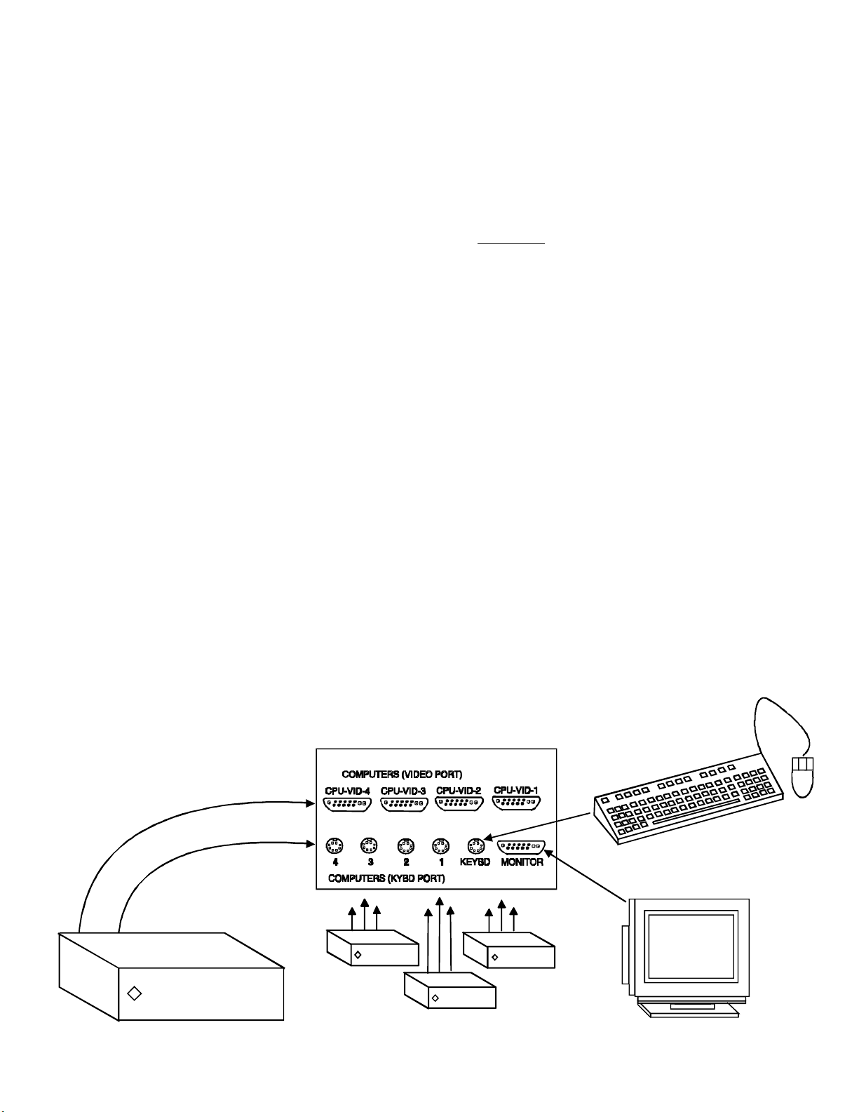
5. For each computer:
Connect a cable from the Keyboard port of the computer to a Keyboard port of the NTI switch. Note the port’s number.
Connect a cable from the Video port of the computer to the Video port of the NTI switch with the same port number as the
keyboard. See the illustration below. Make sure the computer is connected to a Keyboard port and a Video port with the
same number. Otherwise, you may be typing commands to one computer, but viewing a different computer on the monitor.
6. Plug the NTI Switch into an AC power outlet.
7. If you will
8. Connect the RMT to the NTI Switch RMT IN port using the supplied REXT-
NOT
be installing an optional wired remote control (RMT), go to Step 9.
xx
cable.
9. Turn ON power to the NTI Switch, port 1 should illuminate. If it doesn’t, see TROUBLESHOOTING. The NTI Switch supplies
power to the optional RMT.
10. Turn ON power to any or all computers connected to the NTI Switch.
.
SUCEXT-xx
SUKINT-xx-MM
SUN WORKSTATION
SUN WORK STATIO N
SUN WORKST ATIO N
SUN WORKSTAT IO N
2
Page 3
KEYBOARD CONFIGURATIO N
(
)
(
)
(
)
(
)
The dip-switches on the front panel are configurable for several tasks. Switches 1-6 are used for cascading actions (see
CASCADING section) and switches 7 & 8 are for keyboard configuration. These keyboard configuration switches come preconfigured with switch 7 in the “ON” position and switch 8 in the “OFF” position. You should not change these settings as this will
cause your SUN keyboard to not work. Should the positions of switch 7 or 8 get changed, you will need to power down the entire
system (including CPU’s), change the dip-switches back to the required position and then power the system back up. Should you
find the need to replace one SUN keyboard with another one, it can be hot swapped without powering down. Refer to Table 1 and
the following diagram for instructions on proper keyboard dip-switch configuration.
Keyboard dip-switch configuration
(* default settings)
Table 1
Keyboard / Mouse type SW7 SW8
SUN* ON OFF
Switch 7 - ON
Switch 8 - OFF
NETWORK
TECHNOLOGIES
INCORPORATED
17,
SE-8M13W3-8-A
12345678
ON
OFF
CASCADING
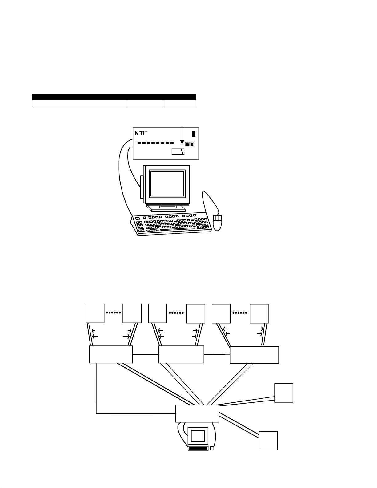
The SUN switch can be expanded to access up to 128 CPU’s by cascading multiple units together. Up to 8 SUN switches can be
connected into another switches CPU ports, as illustrated below. The SUN switch connected to the monitor & keyboard must be
configured as the “MASTER” unit (via dip-switc he s). Any switches connected to the “MASTER” must be configured as “SLAVE”
units. All SUN switches are fully configurable for this expansion method, the only additional hardware required is a set of
keyboard, monitor & RMT extension cables for each “SLAVE UNIT” (see materials).
SUN
SUKINT-xx-MM
SUCEXT-xx
KEEMUX-S8
slave unit 1
SUKINT-xx-MM
REXT-SR-xx
SUN
REXT-SR-xx
SUCEXT-xx
SUN SUN
SUKINT-xx-MM
SUCEXT-xx
KEEMUX-S8
slave unit 2
SUKINT-xx-MM
SUCEXT-xx
KEEMUX-S8
master unit
SUN
REXT-SR-xx
SUN
SUKINT-xx-MM
SUCEXT-xx
KEEMUX-S8
slave unit 3
SUCEXT-xx
SUKINT-xx-MM
SUCEXT-xx
SUKINT-xx-MM
SUCEXT-xx
SUN
SUKINT-xx-MM
SUN
3
Page 4

1. LIMITATIONS
a. All the slave uni ts must be th e sam e size (4, 8 or 1 6 port)
b. Up to 8 slave units may be connected to form a maximum system size of 128 ports (1x8 port master + 8x16 port slaves).
c. Slave units must be added to the master unit in order (slave #1 to master’s port 1, slave #2 to master’s port 2, etc).
Master Unit Port 1 (with an 8-port Slave Unit con nected to it) will become ports 1-8 (1-4 for a 4-port slave , 1-1 6 for a 16-
NOTE:
port, etc.). Master Unit Port 2 (with a second 8-port Slave Unit connected) will become port numbers 9-16 (5-8 for a 4-port slave,
17-32 for a 16-port slave, etc.).
d. All units must be powered OFF during configuration and interconnecting.
e. F or a Master G reater than 8 ports, only t he fir s t 8 ports ma y be configured f or the M ast er/Slave option. The remaining ports
on the mas ter are num bered from t he last por t of the last slave.
In a 1x32 Master w/8 1x8 slaves (8 slaves being the
Note:
maximum number allowed),ports 9-32 on the Master would become ports 65-88.
2. CONFIGURATION:
All units are configured using the 8-position switch (located on the front of each unit) according to the tables below (2-4):
Table 2 *
(default settings)
Table 3
Switch Master Slave Slave Unit Size SW5 SW6
SW1 OFF* ON Not Cascaded OFF OFF
SW7 ON* ON 4 Port OFF ON
SW8 OFF* OFF 8 Port ON OFF
SW5 SEE TBL 3 OFF* 16 Port ON ON
SW6 SEE TBL 3 OFF*
Table 4 *
(default settings)
SW2 SW3 SW4 MASTER SLAVE
OFF* OFF* OFF* 1 slave attached Unit #1
OFF OFF ON 2 slaves attached Unit #2
OFF ON OFF 3 slaves attached Unit #3
OFF ON ON 4 slaves attached Unit #4
ON OFF OFF 5 slaves attached Unit #5
ON OFF ON 6 slaves attached Unit #6
ON ON OFF 7 slaves attached Unit #7
ON ON ON 8 slaves attached Unit #8
3. CASCADED INSTALLATION
a. Configure each switch as per abov e tables before proceeding.
b. Perform steps 1 & 2 under INSTA LLATIO N for eac h s lav e unit.
c. Wit h a SUCEXT-xx cable, connect slave #1 monitor port to master’s CPU-VID 1 port.
d. With a SUKINT/SUKEXT-xx-MM cable, connect slave #1 keybd port to master’s key 1 port.
e. Repeat steps c. & d. for each addit ional s lav e unit, keep in mind that each slave will connect into the next
available master’s port (i.e. slave #2 to master’s vid-2 CP U & key- 2, et c.)
f. With a RMT extension cable, c onnec t master’s RMT out port to slave #1’s RMT in port.
g. With another RMT extension c able, connect slave #1 RMT out port to slave #2’s RMT in por t.
h. Repeat step g. until all slave units are connected together.
i. Repeat the installation sect ion of the manual for any CPU’s to be connected to the master .
NOTE: If you are using an optional wired remote, it will be connected to the master swit ches RMT IN port.
MASTER UNIT (K EEMUX-S4)
CPU-VID-4
KEY-4
KEY-3
CPU-VID-3
KEY-2
KEY-1
CPU-VID-2
KEYBD
CPU-VID-4
KEY-4
SLAVE UNIT #1 (KEEMUX-S4)
CPU-VID-3
KEY-3
CPU-VID-1
MONITOR
KEY-2
Fig 1
KEY-1
4
CPU-VID-2
KEYBD
CPU-VID-1
MONITOR
KEY-3
CPU-VID-3
KEY-2
KEY-1
CPU-VID-2
KEYBD
CPU-VID-4
KEY-4
SLAVE UNIT #2 (KEEMUX-S4)
CPU-VID-1
MONITOR
Page 5

USING THE NTI SWITCH
The switch can be operated by the front control panel or by keyboard control.
Front Panel Control
1. Pressing any touch switch on the front panel will connect the selected computer to the keyboard, monitor, and mouse.
2. Holding down any front panel touch switch for more than 2 seconds will cause the switch to cycle through 3 extended modes
of operation: SCAN, BROADCAST and COMMAND (described in the
Keyboard Control
panel indicate when these modes are enabled. Release the touch switch when the LED’s show that the mode you desire is
On.
Keyboard Control
In order to control the switch with your keyboard, COMMAND Mode must be enabled. To enable or disable COMMAND Mode
from the keyboard:
• Press “CTRL” and “`” (accent key) at the same time.
All 4 status lights on the keyboard will light to indicate that command mode is enabled.
When the COMMAND LED is on, the following functions are available:
Table 4
→
←
S
B
Txxx
(Command Functions)
Increment port
Dec reme nt port
Enable/disable Scan Mode
Enable/disable Broadcast Mode
Sets scan time out period on each port. xxx = number of seconds which can be set from 002 to 255 (for example: t002
would set time out to 2 seconds).
Pxx
NOTE: Y
FRONT PANEL FOR MORE THAN
Selects a specific port. xx = port number as a two-digit number (ex. p01, p08, p15, etc.)
OU MUST EXIT COMMAND MODE TO TYPE TO A COMPUTER
2
SECONDS
OR
PRESS <ESC
. T
O EXIT COMMAND MODE EITHER HOLD DOWN ANY TOUCH SWITCH ON THE
>,
OR PRESS <CTRL
> +
(ACCENT ) KEYS SIMULTANEOUSLY
`
section below). 3 LED’s on the front
.
SCAN
When the SCAN LED is on, the switch scans through all powered ON CPU ports. By default, each port is active for 5 seconds
before switching to the next port. This time out period can be changed in COMMAND Mode described in Table 1.
NOTE: I
HAVE BEEN IDLE FOR A FULL TIME
BROADCAST
F YOU TYPE OR MOVE THE MOUSE WHILE A PORT IS ACTIVE, THAT PORT WILL REMAIN SELECTED UNTIL THE KEYBOARD AND MOUSE
-
OUT PERIOD
.
(use with extreme caution)
BROADCAST Mode allows the operator to send keystrokes to all active computers simultaneously. However, BROADCAST Mode
has some critical requirements:
1. BROADCAST LED must be OFF when booting any attached computers.
2. BROADCAST LED must be ON and COMMAND LED must be off for keystrokes to reach attached computers.
KEYBOARD UPDATING
Keyboard configuration of each computer is saved in the NTI Switch. For example, if the computer attached to Port 4 had CAPS
LOCK and NUM LOCK selected the last time that computer was access e d, then they will auto matically be set when that computer
is accessed again.
5
Page 6

HOW TO DISABLE OPERATING MODES
g
The three operating modes of the KEEMUX-Sx SUN KVM switch can be disabled if a user desires to do so. The Command
Mode can be disabled which would also disable the Scan and Broadcast Modes, or, the Scan and/or Broadcast Modes can be
individually disabled leaving the other features in Command Mode enabled.
To disable these operating modes, the user must get access to the jumpers block. This block is located close to the dip
switches on the circuit board the keyboards plug into (called the digital board) inside the KEEMUX-Sx.
Rear Panel
Front Panel
the 9 screws from the cover to gain acc e s s. With the cover remove d , the jump ers block will be easy to locate. Follow the
instructions under "CONFIGURING THE JUMPER BLOCK" on page 9 to disable the desired mode(s).
If the unit is in a plastic case, the digital board is located on the bottom of the case, requiring the user to partially disassemble the
unit to gain access to the jumpers block. If the unit has the OSD option (KEEMUX-Sx -O), the procedure will be different than
the procedure used if the unit does not have the OSD option.
For models KEEMUX-Sx (no OSD):
Closeup view of jumper block on digital board.
LED board
Video Board
Di
ital Board
The jumper block is located
below the LED board.
JUMPER BLOCK
B
S
R
C
D
A
C
N
L
K
C
C
D
M
E
D
DIP SWITCHES
Overhead view of video board on top of digital board.
If the unit is a rackmount style, the digital board is located directly beneath the cover of the unit, requiring the user to onl y remove
1. Make sure the KEEMUX-Sx is completely disconnected from all computer components. Be sure to
unplug the KEEMUX-Sx from the electrical outlet.
2. Remove the two philips-head screws from the underside of the KEEMUX-Sx and set the KEEMUX-Sx on
a firm and flat surface, bottom down.
Philips-head screws
holding the plastic case
together
View of bottom of plastic case
3. Remove the top half of the plastic case from the KEEMUX-Sx.
6
Page 7

NOTE: Before proceeding, it is important to discharge any static charge you may be carrying by touching any large metal object
(away from the KEEMUX-Sx).
4. The first visible circuit board, the uppermost board, is the video board
5 Along the back of the video board are between 3 and 5 video ribbons (depending on how many monitors
the unit is designed to connect to) connecting the video board to a circuit board on the rear panel with
15HD connectors on it. Disconnect the flat ribbon cables from the video board to each header on the
rear panel. Take note as to where they go for re-assembly later. Do not disconnect them from the video
board headers.
6. There are 4 nuts that secure the video board to standoffs. Remove the 4 nuts.
15HD Connector
Rear Panel
Disconnect video
ribbons here
LED Boar d
Front Panel
Nuts (4) secur e th e circui t b o ar d
to the standoffs.
Video Board
Digital Bo ard
The jumper block is located
below the LED board.
Overhead view of video board on top of digital board.
To avoid further more difficult disassembly, the video board and front panel will be removed from the KEEMUX-Sx as an
assembly.
7. Carefully loosen the video board from the standoffs. With it loosened, grasp firmly the video board and
front panel at the same time and slide the front panel up out of the slots in the plastic case that support it.
Once clear of the case, pivot the assembly back approxi matel y 1", just enough to expose the jumper
block. Be careful not to dislodge the connection of the ribbon connecting the front panel to the digital
board. If it appears to become loose, be sure to reseat the connection before re-assembly. Now follow
the instructions under "CONFIGURING THE JUMPER BLOCK" on page 9.
Lift and pivot board and front
panel......
Ribbon from LED
board to digital board
Be careful not to scratch the bottom
of the circuit board on standoff
threads.
Jumper block
....and set back enough
to clear jumper block.
Standoffs
Set video board and front panel assembly back far enough to clear jumper block.
7
Page 8

For models KEEMUX-Sx-O (with OSD):
g
g
g
g
1. Make sure the KEEMUX-Sx-O is completely disconnected from all computer components. Be sure to
unplug the KEEMUX-Sx-O from the electrical outlet.
2. Remove the two philips-head screws from the underside of the KEEMUX-Sx-O that hold the plastic
case together. Remove the 4 torx-head screws from the underside as well. These hold the lower circuit
board to the plastic case. Turn the KEEMUX-Sx-O back over and set it on a firm and flat surface.
Torx-head screws
holdin
in the digital
board
Philips- head screws
holdin
to
plastic case
ether
View of bottom of plastic case
3. Remove the top half of the plastic case from the KEEMUX-Sx-O.
NOTE: Before proceeding, it is important to discharge any static charge you may be carrying by touching any large metal object
(away from the KEEMUX-Sx-O).
4. Firmly grasp the front and rear panel and slide the entire assembly out of the lower case.
5. Remove the jack screws from the video and monitor connectors on the rear panel. Remove the rear
panel from the assembly.
6. The uppermost board is the video board. Remove the 4 hex nuts securing the video board to standoffs.
Jack Screw
Rear Panel
LED Boar d
Front Panel
15HD Connector
Nuts (4) secure the circuit board
to the standoffs.
Video Board
Di
ital Board
The jumper block is located
below the LED board.
Overhead view of video board on top of digital boa rd .
8
Page 9

7
. Carefully loosen the video board from the standoffs. With it loosened, grasp firmly the video board and
front panel and remove the video board from the standoffs. Once clear of the standoffs, pivot the
assembly back approximately 1", just enough to expose the jumper block. Now follow the instructions
under "CONFIGURING THE JUMPER BL OCK" on page 9.
Lift and pivot board and front
panel......
Ribbon from LED
board to digital board
Be careful not to scratch the bottom
of the circuit board on standoff
threads.
Jumper block
....and set back enough
to clear jumper block.
Standoffs
Set video board and front panel assembly back far enough to clear jumper block.
CONFIGURING THE JUMPER BLOCK
With the jumper block exposed, apply a jumper across the appropriate pins to disable the desired mode(s) according to the
chart below.
Pin Designation Mode
KCMD Command Mode*
BRDC Br oadc as t Mode
SCAN Scan Mode
*Note: Putting a jumper ac r os s pins KCM D to
JUMPER BLOCK
B
S
R
C
D
A
C
N
If the unit has an L CD
this jumper will be here.
L
K
C
C
D
M
E
D
disable Command Mode will also disable
Broadcast and Scan Modes.
DIP SWITCHES
DEFAULT JUMPERS
Drawing shows jumper across SCAN pins, disabling Scan Mode.
Broadcast Mode is still enabled.
JUMPER
Once the desired jumpers are in place, reverse the disassembly process to re-assemble the KEEMUX-Sx
(or KEEMUX-Sx-O). Be particularly careful about connecting the ribbons back to the headers they were removed from and to
fully insert the ribbons to the headers. Note: The text on the video ribbons (non-OSD version) should face the right-hand side of
the case after insertion. Do not turn the power ON until all connections have been completely and properly made and the unit
has been properly re-assembled.
9
Page 10

Technical Specifications:
8 Mini DIN
Keyboard/Mouse
PIN # SIGNAL PIN # SIGNAL PIN # SIGNAL
1 Ground 1 Gr ound 9 I D 0
2 Ground 2 V sync 10 Ground
3 +5V 3 ID 2 A1 Red
4 Mouse 4 Ground A2 Green
5 Kybd Receive 5 C sync A3 Blue
6 Kybd Transmit 6 H sync
7 Pwr N 7 Ground
8 +5V 8 ID 1
13W3 Monitor
Mating face of a MALE
8mD Connector
Mating face of a MALE
13W3 Connector
6
3
7
45
8
12
1
67
345
2
9
8
10
TROUBLESHOOTING
1. Verify that all cables are securely connected.
2. Verify that the computer is connected to a Keyboard port and Video port with the same port number.
3. If the cable from a computer’s Keyboard port is disconnected from the NTI Switch while power is on, turn the power OFF to
the computer before plugging the cable back in.
4. Verify port 1 LED illum inat e s when switch is turned ON. If it doesn’t, call NTI for a ssis tance.
5. If a SUN SPARC-10 will not power up, connect to the SPARC through the switch and press the "POWER" key (only available
on type 5 and 5C keyboards).
6. Turn ON power to NTI Switch first, then to the computers.
NOTE: A
LWAYS TURN POWER ON IN THIS SEQUENCE
.
WARRANTY INFORMATION
The warranty period on this product (parts and labor) is one (1) year from the date of purchase. Please contact Network
Technologies Inc at
information regarding repairs and / or returns. A return authorization number is required for all repairs/returns.
(800) 742-8324 (800-RGB-TECH)
(330) 562-7070
or
or visit our website at http:// www.nti1.com for
COPYRIGHT
Copyright © 2001 by Network Technologies Inc. All rights reserved. No part of this publication may be reproduced, stored in a
retrieval system, or transmitted, in any form or by any means, electronic, mechanical, photocopying, recording, or otherwise,
without the prior written consent of Network Technologies Inc, 1275 Danner Drive, Aurora, OH 44202
CHANGES
The material in this guide is for information only and is subject to change without notice. Network Technologies Inc reserves the
right to make changes in the product design without reservation and without notification to its users.
SERIAL NO.:
KEEMUX-S-___
DATE:
INSPECTED BY:
10
 Loading...