

NTI GF200, NPE-240A Quick Installation Manual
GF200
Quick Installation Guide
STEP 1 - BEFORE INSTALLING
Read both the GF200 and NPE-240A
Installation manuals before installing.
This product must be installed and serviced
by a licensed plumber, a licensed gas tter, or
a professional service technician. NTI is not
liable for any damages or defects resulting
from improper installation.
When applicable, the installation must conform with Manufactured
Home Construction and Safety Standards, Title 24 CFR, Part 3280
and/or CAN/CSA Z240 MH Series, Mobile Homes.
Safety
WARNING
Follow all local codes and/or the most recent edition of the National
Fuel Gas Code (ANSI Z223.1/NFPA 54) in the USA, or the Natural Gas
and Propane Installation Code in Canada (CAN/CGA B149.1).
GF 200
Installation Manual
C
learan
ces [D
ég
age
ments
]
GF 200
C
O
M
BINAT
ION GAS WAT
ER HEA
T
ER /
CENT
R
AL
AIR HEA
T
ING
*COMBINA
ISO
N
CHAU
F
F
EEEAU INST
ANT
ANE / GENERAT
EUR
D'
AIR CH
AUD
####
#
Ma
de
in
C
an
a
da
Fab
r
iq
u
es
a
u C
an
a
d
a
Seria
l Nu
m
b
er
:
####
#
####
#
#
####
###
##
#
####
AIR
FL
OW
T
h
is ap
p
lia
n
ce
is ap
p
ro
v
ed
f
o
r u
p
f
lo
w in
stal
latio
n
.
C
ette f
our
n
ai
s
e e
s
t a
ppro
v
e
e pou
r l
'
i
ns
tal
l
a
ti
on
et c
i
r
c
ul
a
ti
on
d'ai
r as
c
ende
nte.
Min
.
clearan
ce t
o
c
o
mb
u
st
ib
le co
n
st
ru
ct
io
n
: (
i
n
.)
see d
iag
ram
.
Dega
gemen
ts
mi
ni
mum en
tr
e l
'app
arei
l
et des
c
ons
tru
c
ti
ons
c
ombu
s
ti
bl
es
(
PO.)
Ven
t
cl
earan
ce to
co
m
b
u
st
ib
le
co
n
stru
ct
io
n
(
in
.)
: 0
D
egag
ement d
e v
ent c
ons
tr
uc
ti
on
s
c
ombu
s
t
i
bl
es
(
PO.):
0
* Min
s
ervice
cleara
n
ce
* D
egag
emen
t mi
n. p
our
fi
n
s
d
'
e
ntr
e
ti
en
pou
r
l
e
s
i
ns
tal
l
a
ti
o
ns
C: CO
MBU
ST
IBLE F
LOORS
Re
fer
t
o Ins
tal
l
a
ti
o
n Manu
al
f
or
s
er
v
i
c
e
c
l
ear
anc
e de
tai
l
s
0
0
0
0
2
4*
C
Elec
t
rical
Rat
i
n
g
/ Car
ac
t
er
i
s
t
i
qu
e El
e
c
tr
i
q
ue
VOL
T
S
F
R
EQ
.
PHASE
MCA
MA
X. CKT
. BR
K
IN
DO
O
R
BLOWER MOT
OR
12
060 Hz
1
1
3 A
9
.6 A
3/
4
F
LA
HP
C
e
rtifi
e
d
by
C
e
r
t
ifie
p
ar
N
Y
The
rma
l I
n
c
. 3
0
S
to
ne
ga
te
D
r
.,
S
a
int
Jo
hn
, N
B
,
E
2H
0A4,
C
a
na
d
a
Mo
d
el
[Mo
de
l
e]
F
u
el
[Gaz
]
A
lt
itu
d
e
, ft
[Al
ti
tude
, pi
]
In
p
u
t
, MBH
[Entr
ée, k
W]
Mi
n
Max
Sp
ac
e Hea
t
in
g
Ca
p
ac
it
y, M
BH
[Cap
a
c
i
te d
e
Cha
u
ffag
e
, k
W]
Nat.
19
.9
[5.83]20
0 [58
.61]
0 4500
*
T
GF
-20
0
L
P
D
HW Hea
tin
g
Cap
acit
y, MBH
[
Capac
i
te de
DHW
C
hauffa
ge, k
W]
80 [23
.45]
200
[58.61
]
F
AC
T
ORY SET
F
O
R N
AT
U
RAL
G
A
S
F
i
el
d
c
o
nv
er
ted
to Pr
op
an
e Gas
CO
NF
I
G
U
R
ÉE
A L
'
USIN
E POUR GAZ
NAT
UREL
Co
nv
er
ti
e au
pro
pane
s
ur
pl
ac
e
Date:_
___
_
____
_
____
____
_____
____
_____
D
ate:__
____
____
_____
____
____
_____
__
__
Gas Press
u
re [Pr
e
s
s
i
on du
G
a
z
]
Natu
ral
[Natu
r
el
]
Pro
p
an
e
Maxim
u
m
In
let
Gas
Pressu
re
[Pr
es
s
i
on
max
i
ma
l
e d
'
e
ntré
e du
gaz
]
Min
im
u
m
In
let Gas
Pressu
re [Pr
e
s
s
i
on mi
ni
mu
m d'
entr
ée d
u gaz
]
Man
i
fo
ld
Pres
s
u
re
[
Pres
s
i
on
d'admi
s
s
i
on]
10
.5
" WC
3.5"
W
C
-
0.58
" WC
13
"
WC
8"
W
C
-
0.
02 / -
0.78"
WC
I
m
p
o
rt
an
t I
n
fo
rm
at
io
n
[Rens
i
gnes
men
t
s
Im
porta
nts
]
Us
e
for
Natur
al
or L
P G
a
s
o
nl
y
.
Max
i
mum
W
a
ter
Pr
es
s
u
re = 1
50 ps
i
Max
i
m
um Stati
c
Pres
s
ure =
0.8 IN
. W.C.
Max
i
mum Inl
et Wat
er
T
empe
r
atur
e = 18
0°
F
T
h
i
s
app
l
ian
c
e mu
s
t b
e i
n
s
ta
l
led
i
n ac
c
or
d
anc
e
wi
th l
oc
al
c
od
es
, i
f
any
; i
f
not,
fol
l
ow
ANSI
Z
223
.1/NF
PA 54 o
r
CAN
/CSA B14
9.1, N
atura
l
Gas
and
Pr
opa
ne In
s
ta
l
l
ati
on Co
de, a
s
a
ppl
i
c
abl
e.
Uti
l
i
s
e
z
d
es
gaz
Nat
ur
el
ou
LP s
eulement.
Pr
es
s
i
o
n d'eau
max
. = 150
l
b
/po²
Pr
es
s
i
on
s
t
ati
q
ue max
. = 0
.8 PO. D'EAU
T
emp.
max
i
mal
e d'
ea
u d'en
tr
ée
= 180°
F
Cet a
ppar
ei
l
do
i
t ê
tr
e i
ns
tal
l
é
c
on
formé
ment au
x
c
od
es
l
oc
aux
, l
e c
as
éc
héan
t ; s
i
n
on, s
ui
v
e
z
AN
SI Z
22
3.1 /
NF
PA 54
o
u CAN
/ CSA B14
9.1, g
az
natur
el
et
prop
ane
C
ode
d
'
i
ns
tal
l
a
ti
on
, l
e
c
a
s
éc
h
éan
t.
F
OR YOUR
SAF
ET
Y
Do
not s
tor
e or
us
e gas
ol
i
n
e or
other
fl
a
mmabl
e v
ap
or
s
a
nd l
i
q
ui
d
s
i
n th
e v
i
c
i
n
i
ty
o
f thi
s
or an
y
o
ther
appl
i
a
nc
e.
POUR
VOT
RE SÉC
URIT
É
Ne p
as
entr
epos
er
ou
uti
l
i
s
er
d'
es
s
en
c
e
ou d'au
tres
v
apeu
r
s
et l
i
qu
i
d
es
i
nfl
ammab
l
es
à
pr
ox
i
mi
té
de
c
et
app
ar
ei
l
ou de
tout
autr
e
appa
rei
l
.
St
an
d
ard
ANSI Z
21.1
0.3 / C
SA 4.3
Gas
Water
Hea
te
rs
, Vol
ume III
Stora
ge Water
Hea
ters
, wi
th In
put R
ati
ngs
Abov
e 75
,00
0
BT
U
pe
r
Hou
r, Ci
r
c
ul
ati
ng a
nd
Ins
ta
ntaneo
us
CSA C2
2.2 N
o
. 23
6 / UL
199
5
Heat
i
ng
and C
ool
i
ng
Equi
pmen
t
*
R
e
f
e
r
to
w
a
te
r
h
e
ate
r r
a
tin
g
pla
te
u
nd
e
r
a
c
c
ess
p
an
el
on
t
he
o
pp
o
s
ite
si
d
e
of
th
is c
a
b
in
et.
Orifice
s
ne
ce
ss
ary fo
r
L
P
c
o
nv
e
r
s
io
n
are
pro
v
ide
d
.
Failu
r
e
to
u
se
t
he
co
r
re
ct
ga
s c
a
n
c
au
se
pro
bl
e
ms
w
hic
h
ca
n re
s
ult
in
d
ea
th
,
s
eriou
s
inju
r
y
o
r
p
r
o
p
erty
d
ama
g
e
Le
s
inje
c
t
ures
n
e
ce
ss
a
ires
a
l
a
co
nv
ersio
n
a
u
G
P
L
s
o
nt
f
o
u
r
n
is.
Le
f
ait
de
n
e
pa
s
u
tilis
er le
b
on
g
az
p
eu
t c
a
u
se
r
de
s
p
r
ob
le
mes
qu
i p
e
u
ve
n
t
me
ne
r
a
la
mo
rt, c
au
s
e
r
de
s
b
e
ssu
res
g
r
a
ve
s o
u
e
nd
omma
ge
r
la
prop
r
ie
te
24*
24*
W
a
t
er h
ea
t
e
r ratin
g
p
lat
e
lo
ca
ted
u
n
d
er a
cces
s p
a
n
el o
n
o
p
p
o
s
ite s
id
e o
f
c
ab
in
et.
20 A
DO NOT install in areas with excessively
high humidity or poor air quality (dust,
particulate matter, etc.)
STEP 2 - INSTALLING
1
Unpacking
GF 200
Installation Manual
Cleara
nces [Dégage
ments]
GF 200
COMB
INATIO
N GAS WATER
HEAT
ER / CEN
TRAL
AIR HEA
TING
*C
OMBINA
ISON CH
AUFF
EE-EAU I
NSTANT
ANE / GEN
ERATEU
R
D'AIR
CHAU
D
#####
M
ad
e in Can
ada
Fa
brique
s
au
Cana
da
Serial Number:
#####
#####
#####
#####
#####
AIR FLO
W
Th
is appliance is ap
proved fo
r upflo
w install
ation.
Cette fournaise
est approvee pou
r l'ins
tallation et c
irculation
d
'air asc
endente.
Min. clearance to comb
ustible co
nstruct
ion: (in
.) see diagra
m.
Dega
gements m
inimum
entre l'a
ppareil et des
construction
s combusti
bles (PO.)
Ve
nt clearance to
combu
stible cons
truction
(in.): 0
D
egagement de v
ent construct
ions combus
tibles (PO.
): 0
* Min
service clearan
ce
*
Degagement
min. pour
fins d'ent
retien pour les
installatio
ns
C
: COMBUSTIBLE
FLOORS
Refer t
o Installation Manual for ser
vice cleara
nce details
0
0
0
0
24*
C
Electr
ical Rating
/ Caracte
ristique El
ectrique
VOLTS
FREQ.
PHASE
MCA
MAX.
CKT. BR
K
IND
OOR BLO
WER MOTOR
12060 Hz
1
13 A
9
.6 A
3/4
F
LA
HP
Certi
fied
b
y
Certifie
p
ar
NY
The
r
m
al I
n
c. 30 Ston
ega
t
e
Dr.
, Sain
t
John, N
B, E2H 0A4
, Ca
nad
a
Model
[Modele]
Fuel
[Gaz
]
Alt
itude, ft
[Alti
tude, pi]
Inpu
t, MB
H
[Entrée, kW]
Min
Max
Space H
e
a
ting
Capacity
,
MBH
[Capaci
te de
C
hauffage, kW]
N
at.
19.9 [5.83]200 [58.61]
0 - 4500*
TGF-20
0
LP
D
HW He
ating
Capacity,
MBH
[Capacite de D
HW
Chauffage, kW
]
80 [23.45]200 [58.61]
FAC
TORY SET
FOR N
ATUR
AL GAS
Field
c
onverted to P
ropane Gas
CON
FIGURÉE A L'US
INE POU
R GAZ
NATUR
EL
C
onvertie au pr
opane sur pl
ace
Date:_______
_
_
___________________
_
_
__
Date:_____
_
_
______________________
_
_
_
Gas Pressu
re [Press
ion du Gaz]
N
atural [Natur
el]Propane
Max
imum Inle
t Gas Pressu
re [Pressi
on maxim
ale d'e
n
t
rée du gaz]
Minimum
Inlet G
a
s
Pressure [Pre
ssion mini
mum d'entrée du gaz]
Ma
nifold Pre
ssure [Pressi
on d'admission]
10.5" WC
3.5" WC
-0
.
5
8" WC
13" WC
8" WC
-0.02 / -
0
.
78" WC
Impo
rtant In
formati
on [Rensign
esments Importants]
Use
for Natural
or LP Gas onl
y.
Maximum Water Pressur
e = 150 psi
Maximum Stati
c Pressur
e = 0.8 IN.
W.C.
Maximu
m Inlet Wate
r Tempe
rature = 180°F
This appl
iance mu
st be installed
in accordance
with local
codes, if any; if
not, follow AN
SI
Z223.1/N
FPA 54 or C
AN/CSA
B149.1, Natura
l
Gas
and Propane Instal
lation Code, a
s
applic
able.
Ut
ilisez des ga
z Naturel
ou LP seulement.
Pres
sion d'ea
u max. = 150 lb/po²
Pre
ssion statique
max. = 0.8 PO. D'EAU
Temp. ma
ximale d'eau d'entrée =
180°F
Cet appare
il doit être i
nstallé conformément aux c
odes
locaux
, le cas éc
héant ; sinon, sui
vez ANSI Z
223.1 /
N
FPA 54 ou C
AN / CS
A B149.1, gaz nature
l et
prop
ane Code d'installation
, le cas échéa
nt.
FOR
YOUR SA
FETY
Do no
t
s
tore or use gas
oline or other
flammable vapors
and liquids in
the vicinity
of this or any othe
r appliance.
POU
R VOTR
E SÉCURITÉ
Ne pas e
ntreposer ou util
iser d'e
ssence ou d'autres
vapeurs
et liquides i
nflammabl
es à proxim
ité de cet
appareil ou de t
out autre apparei
l.
Standard AN
SI Z21.10.3 / C
SA 4.3
G
as Water H
eaters, Vol
ume III Storage
Water
He
aters, with
In
put Ratings
Above 75,000 BTU
per Hour, C
irculati
ng and Instantaneous
CSA
C22.2 No. 236
/
UL 1995
Heating and C
ooling Equipm
ent
*
Refer t
o
water hea
te
r
rating pla
t
e
u
nde
r access
pan
el on
the o
ppo
site side
o
f this
cab
i
n
et.
Ori
fice
s ne
ce
ssary
for LP conversi
o
n are provide
d.
Failure to use t
h
e c
o
r
re
ct
g
as
can
cau
se
p
roblem
s
wh
ic
h
can
result i
n
d
eath, se
ri
o
us
in
jury or prop
erty
da
mag
e
L
es
inje
ctures necess
a
ir
e
s
a la c
o
nversi
o
n au GP
L so
nt
fourn
i
s.
Le fait
d
e ne pa
s utilis
e
r
le bo
n gaz peu
t causer des
proble
mes qui pe
uvent men
er a la m
ort,
causer des bess
u
res
g
r
a
v
e
s
ou
e
ndo
mma
ge
r
la prop
ri
e
te
24*
24*
Water h
eater rating
plate locat
ed und
er access pan
e
l
on opp
osite side
o
f cabinet.
20 A
KIT BOX
GF200
Manual Packet
LP Conversion Kit
Spare Parts Kit
Installation Kit Box
When you unpack the GF200, you will nd
the
following items inside the appliance. Check
for each of the following items before installing
the appliance.
1
2
Location Requirements
Install the appliance in an area that allows for service and maintenance access
to utility connections, piping, ductwork, lters, and traps. Based on the installation location, ensure the following clearances are maintained:
Minimum clearance:
Clearance to
combustibles
Recommended
service clearances
Top 9 in as required
Back
Front * (or as required)*
Side (w/o connections) as required
Side (w/ connections) as required
Side (Blower access) 24 in
Bottom
When locating the appliance prior to completing the ductwork and plumbing,
it is essential that sucient space be allotted for the installation and maintenance of components such as:
• Flow switch
• Thermostatic Mixing Valve (TMV)
• Pressure Relief Valve (PRV)
• Shut o and drain valves
• Expansion tank (optional)
• Condensate drain (and optional pump)
• Return air lter
• Circulating blower
* No clearance required to front of unit if obstruction is removable (such as a door or access panel). 24
inch clearance if obstruction is permanent.
3
Checking the Rating Plate
Clearances [Dégagements]
IFW-80-200
COMBINATION GAS WATER HEATER / CENTRAL AIR HEATING
*COMBINAISON CHAUFFEE-EAU INSTANTANE / GENERATEUR
D'AIR CHAUD
#####
Made in Canada
Fabriques au Canada
Serial Number:
#####
#####
#####
#####
#####
AIR FLOW
This appliance is approved for upflow installation.
Cette fournaise est approvee pour l'installation et circulation d'air ascendente.
Min. clearance to combustible construction: (in.) see diagram.
Degagements minimum entre l'appareil et des constructions combustibles (PO.)
Vent clearance to combustible construction (in.): 0
Degagement de vent constructions combustibles (PO.): 0
* Min service clearance
* Degagement min. pour fins d'entretien pour les installations
C: COMBUSTIBLE FLOORS
Refer to Installation Manual for service clearance details
0
0
0
0
24*
C
Electrical Rating / Caracteristique Electrique
VOLTS FREQ. PHASE MCA MAX. CKT. BRK
INDOOR BLOWER MOTOR
12060 Hz
1
13 A
9.6 A
3/4
FLA
HP
Certified by
Certifie par
NY Thermal Inc. 30 Stonegate Dr., Saint John, NB, E2H 0A4, Canada
Model
[Modele]
Fuel
[Gaz]
Altitude, ft
[Altitude, pi]
Input, MBH
[Entrée, kW]
Min
Max
Space Heating
Capacity, MBH
[Capacite de
Chauffage, kW]
Nat.
19.9 [5.83]200 [58.61]
0 - 4500*
IFW-80-200
LP
DHW Heating
Capacity, MBH
[Capacite de DHW
Chauffage, kW]
80 [23.45]200 [58.61]
FACTORY SET FOR NATURAL GAS
Field converted to Propane Gas
CONFIGURÉE A L'USINE POUR GAZ NATUREL
Convertie au propane sur place
Date:________________________________
Date:________________________________
Gas Pressure [Pression du Gaz]
Natural [Naturel]Propane
Maximum Inlet Gas Pressure [Pression maximale d'entrée du gaz]
Minimum Inlet Gas Pressure [Pression minimum d'entrée du gaz]
Manifold Pressure [Pression d'admission]
10.5" WC
3.5" WC
-0.58" WC
13" WC
8" WC
-0.02 / -0.78" WC
Important Information [Rensignesments Importants]
Use for Natural or LP Gas only.
Maximum Water Pressure = 150 psi
Maximum Static Pressure = 0.8 IN. W.C.
Maximum Inlet Water Temperature = 180°F
This appliance must be installed in accordance
with local codes, if any; if not, follow ANSI
Z223.1/NFPA 54 or CAN/CSA B149.1, Natural
Gas and Propane Installation Code, as
applicable.
Utilisez des gaz Naturel ou LP seulement.
Pression d'eau max. = 150 lb/po²
Pression statique max. = 0.8 PO. D'EAU
Temp. maximale d'eau d'entrée = 180°F
Cet appareil doit être installé conformément aux codes
locaux , le cas échéant ; sinon, suivez ANSI Z223.1 /
NFPA 54 ou CAN / CSA B149.1, gaz naturel et
propane Code d'installation, le cas échéant.
FOR YOUR SAFETY
Do not store or use gasoline or other
flammable vapors and liquids in the vicinity
of this or any other appliance.
POUR VOTRE SÉCURITÉ
Ne pas entreposer ou utiliser d'essence ou d'autres
vapeurs et liquides inflammables à proximité de cet
appareil ou de tout autre appareil.
Standard ANSI Z21.10.3 / CSA 4.3
Gas Water Heaters, Volume III Storage Water
Heaters, with Input Ratings Above 75,000 BTU
per Hour, Circulating and Instantaneous
CSA C22.2 No. 236 / UL 1995
Heating and Cooling Equipment
* Refer to water heater rating plate under access panel on the opposite side of this cabinet.
Orifices necessary for LP co
nversion are provided.
Failure to use the correct gas can cause problems
which can result in death, serious injury or property
damage
Les injectures necessaires a la conversion au GPL sont
fournis.
Le fait de ne pas utiliser le bon gaz peut causer des
problemes qui peuvent mener a la mort,
causer des bessures
graves ou endommager la propriete
24*
24*
Water heater rating plate located under access panel on opposite side of cabinet.
20 A
Rating Plate, *Plaque Signalétique
Direct Vent Automatic Instantaneous Water Heater *Chauffe-eau instantané automatique à évent direct
For Indoor, Outdoor or Manufactured Home (Mobile Home) Installation *Pour installation dans une maison préfabriquée (mobile)
Navien, Inc.
20 Goodyear, Irvine, CA 92618
Tel: 1-800-519-8794
Orifices necessary for LP conversion are provided. *Les injectures nécessaires à la conversion au GPL sont fournis.
Failure to use the correct gas can cause problems which can result in death, serious injury or property damage. *Le fait de ne pas
utiliser le bon gaz peut causer des problèmes qui peuvent mener à la mort, causer des blessures graves ou endommager la propriété.
Consult your installation manual for more information. *Consultez votre manuel d’installation pour plus d’information.
Suitable for combination water (potable) heating and space heating and not suitable for space heating applications only.
*Convient au chauffage combiné de l’eau (potable) et des locaux, mais non au chauffage des locaux seulement.
This appliance is certified for use at altitudes up to 4,500 ft (1,370 m) in accordance to the latest CAN/CGA 2.17-High Altitude Installation
procedures at normal manifold pressure. For installation instructions at altitudes higher than 4,500 ft, please contact Navien. *Cet appareil
est certifié pour une utilisation à des altitudes de 0 à 4,500 pieds (1,370 m) conformément aux toutes les procédures d’installation à haute
altitude CAN/CGA 2.17 à une pression normale. Pour les installations à élévations en haut de 4,500 pieds, appeler le bureau de Navien.
This appliance must be installed in accordance with local codes, or in the absence of local codes, the National Fuel Gas Code, ANSI
Z223.1/NFPA 54 or the CSA B149.1, Natural Gas and Propane Installation Code. *Cet appareil doit être installé selon les règlements
locaux, ou en l’absence de tels règlements, selon le National Fuel Gas Code, ANSI Z223.1/NFPA 54, ou les, Code d'installation du gaz
natural et du propane, CSA-B149.1.
Model No., *Numéro de modèle
NPE-210A
Max. Input Rating, *Entrée GPL max.
180,000 Btu/h
Recovery Rating, *Calibre de recouvrement
Max. Inlet Gas Pressure, *Pression max. de gaz d’entrée
Min. Inlet Gas Pressure, *Pression min. de gaz d’entrée
Manifold Pressure, *Pression d’admission
Electrical Rating, *Régime nominal électrique
Max. Water Pressure, *Pression d’eau max.
Type of Gas, *Type de gaz
NG
Min. Input Rating, *Débit calorifique max.
19,900 Btu/h
265 Gallons/Hour, *gallons/heures
10.5 Inches W.C. *pouces W.C.
3.5 Inches W.C. *pouces W.C.
-0.36 Inches W.C. *pouces W.C.
AC *c.a. 120 Volts 60Hz, less than 2 amperes, *Utilise moins de 2A
150 psi *lb/po2 ANSI Z21.10.3 · CSA 4.3-2011
FOR YOUR SAFETY *POUR VOTRE SÉCURITÉ
Do not store or use gasoline or other flammable vapors and liquids in the vicinity of this or any other gas appliances. *Ne rangez
pas et n'utilisez pas d'essence ou d'autres liquides ou vapeurs inflammables près de cet appareil ou de tout autre appareil électroménager.
Clearances [Dégagements]
GF 200
COMBINATION GAS WATER HEATER / CENTRAL AIR HEATING
COMBINAISON CHAUFFEE-EAU INSTANTANE / GENERATEUR
D'AIR CHAUD
#####
Made in Canada
Fabriques au Canada
Serial Number:
#####
#####
##### #####
#####
AIR FLOW
This appliance is approved for upflow installation.
Cette fournaise est approvée pour l'installation et circulation d'air ascendente.
Min. clearance to combustible construction: (in.) see diagram.
Dégagements minimum entre l'appareil et des constructions combustibles (PO.)
Vent clearance to combustible construction (in.): 0
Dégagement de vent constructions combustibles (PO.): 0
* Min service clearance
* Dégagement min. pour fins d'entretien pour les installations
C: COMBUSTIBLE FLOORS
*Refer to Installation Manual for service clearance details
0
0
0024*
C
Electrical Rating / Caractéristique Électrique
VOLTS
INDOOR BLOWER MOTOR
120 60 Hz
1 12 A
9.6 A
3/4
RATED AMPS HP
Certified by
Certifie par
NY Thermal Inc. 30 Stonegate Dr., Saint John, NB, E2H 0A4, Canada
Model
[Mod
èle]
Fuel
[Gaz]
Altitude, ft
[Altitude, pi]
Input, MBH
[Entrée, kW]
Min
Max
Space Heating
Capacity, MBH
[Capacité de
Chauffage, kW]
Nat.
19.9 [5.83] 200 [58.6]
0 - 4500*
GF 200
LP
80 [23.5]
FACTORY SET FOR NATURAL GAS
Field converted to Propane Gas
CONFIGURÉE À L'USINE POUR GAZ NATUREL
Convertie au propane sur place
Date:________________________________ Date:________________________________
Gas Pressure [Pression du Gaz]
Natural [Naturel] Propane
Maximum Inlet Gas Pressure [Pression maximale d'entrée du gaz]
Minimum Inlet Gas Pressure [Pression minimum d'entrée du gaz]
Manifold Pressure [Pression d'admission]
10.5" WC
3.5" WC
-0.58" WC
13" WC
8" WC
-0.02 / -0.78" WC
Important Information [Rensignesments Importants]
Use for Natural or LP Gas only.
Maximum Water Pressure = 150 psi
Maximum Static Pressure = 0.8 IN. W.C.
Maximum Inlet Water Temperature = 180°F
This appliance must be installed in accordance
with local codes, if any; if not, follow ANSI
Z223.1/NFPA 54 or CAN/CSA B149.1, Natural
Gas and Propane Installation Code, as
applicable.
Utilisez des gaz Naturel ou LP seulement.
Pression d'eau max. = 150 lb/po²
Pression statique max. = 0.8 PO. D'EAU
Temp. maximale d'eau d'entrée = 180°F
Cet appareil doit être installé conformément aux codes
locaux, le cas échéant ; sinon, suivez ANSI Z223.1 /
NFPA 54 ou CAN / CSA B149.1, gaz naturel et
propane Code d'installation, le cas échéant.
FOR YOUR SAFETY
Do not store or use gasoline or other
flammable vapors and liquids in the vicinity
of this or any other appliance.
POUR VOTRE SÉCURITÉ
Ne pas entreposer ou utiliser d'essence ou d'autres
vapeurs et liquides inflammables à proximité de cet
appareil ou de tout autre appareil.
Standard ANSI Z21.10.3 / CSA 4.3
Gas Water Heaters, Volume III Storage Water
Heaters, with Input Ratings Above 75,000 BTU
per Hour, Circulating and Instantaneous
CSA C22.2 No. 236 / UL 1995
Heating and Cooling Equipment
* Refer to water heater rating plate on the opposite side of this cabinet.
Orifices necessary for LP conversion are provided.
Failure to use the correct gas can cause problems
which can result in death, serious injury or property
damage.
Les injectures nécessaires à la conversion au GPL sont
fournis.
Le fait de ne pas utiliser le bon gaz peut causer des
problèmes qui peuvent mener à la mort, causer des blessures
graves ou endommager la propriété.
24*
24*
Water heater rating plate located on opposite side of cabinet.
20 A
FREQ.
PHASE MCAMAX. CKT. BRK.RATED AMPS
15 A
Part # 85477
The GF200 is congured for
Natural Gas from the factory.
If conversion to Propane Gas
is required, the conversion kit
supplied with the water heater
must be used.
• Before connecting the gas supply, determine the gas type and pressure
for the water heater by referring to the rating plate. Use only the same
gas type indicated on the rating plate. Using a dierent gas type will
result in abnormal combustion and malfunction of the water heater.
Gas supplies should be connected by a licensed professional only.
• The appliance and its gas connection must be leak tested before
placing the appliance in operation.
• The water heater cannot be converted from natural gas to propane or
vice versa without the supplied gas conversion kit. Do not attempt a
eld conversion of the water heater without a the gas conversion kit.
Doing so will result in dangerous operating conditions and will void the
warranty.
NTI is not liable for any property damage and/or personal injury resulting
from improper conversions.
WARNING
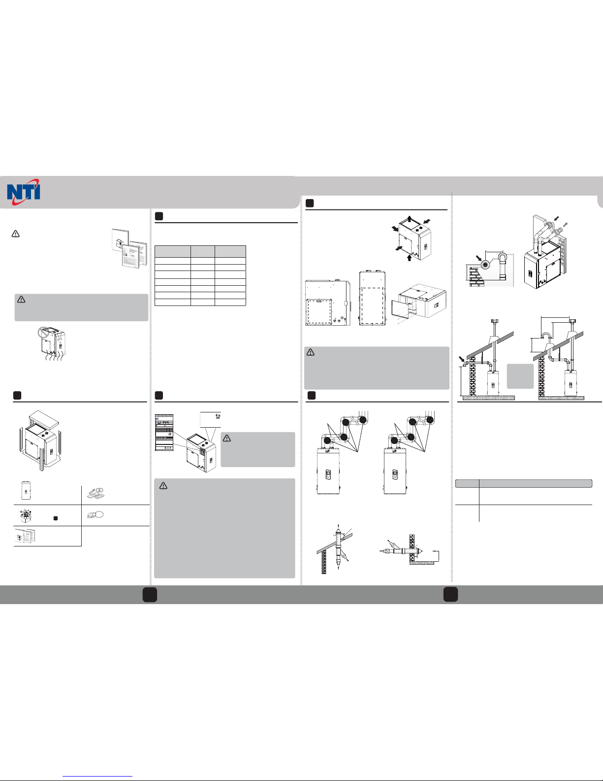
4
Return Air Ducting
The return air may be delivered to the
appliance via:
a) either side;
b) the back;
c) the bottom; or
d) any combination thereof, provided, in
all cases, that access to at least one side
door remains clear (24” min.) for blower
access and maintenance.
MAX CUTTING
BOUNDARY
18” x 18”
(324 sq. in.)
MAX
CUTTING
BOUNDARY
14.5” x 24.5”
(355 sq. in.)
Side Back Bottom
In all installations, an appropriate air ltration system is recommended and
must meet test requirements in UL 900. Failure to install and properly maintain such a system could lead to damage to and/or premature failure of the
space heating components.
In all cases, care must be taken to ensure that return ducting is sealed against
the inlet, such that the entire air steam is directed through the air lter. Failure
to do so could cause damage to the air moving equipment and clogging of
the heating and/or cooling coils.
NOTE: For details and recommendations on side, back or bottom return ducting see
GF200 Installation Manual.
5
Venting
Max length: 150’
Max length: 60’
1
2
8
Max number of
elbows: 8
Max number of
elbows: 6
1
2
6
3” Venting
1 in (25 mm) min.
Combustion Air
Vent
Maintain 12” min. clearance above
highest anticipated snow level or grade.
Combustion Air
Combustion Air
Vent
Maintain 12” min. (18” min. for Canada)
clearance above highest anticipated
snow level.
Max. 24” above roof.
Vent
Combustion Air
2” Venting
Vent Termination Options
Concentric Vent Terminations
12 in (300 mm) min. *
12 in (300 mm) min.
12 in (300 mm) min.
36 in (900 mm) min.
Horizontal Vent Termination
Interior View
Exterior View
Vertical Vent Termination
12” Min
from any
obstruction
above, below,
left or right.
Exhaust Vent Materials
From factory, the GF200 operates at water temperatures exceeding 150°F,
resulting in the potential for exhaust temperatures to exceed 149°F.
As such, high-temperature vent pipe material (CPVC or polypropylene; see table
below) must be used for the rst 3 feet (2" venting) or 0.5 feet (3" venting).
If such materials are unavailable, see the Venting section of the GF200 manual for
instructions on how to limit the maximum water temperature set point.
* Approved polypropylene systems include: Duravent Polypro (Single Wall): 2PPSxxx (2in), 3PPS-xxx (3 in) / Centrotherm Innoue SW: ISxx02xx (2 in), ISxx03xx (3 in)
/ Centrotherm InnoFlue Flex: IFVL02XXX (2 in). Refer to the manufacturer’s literature for detailed information.
** For installation in Canada, eld-supplied plastic vent piping must comply
with CAN/CGA B149.1 (latest edition) and be certied to the Standard. For Type
BH Gas Venting Systems, ULC-S636. Components of this listed system must not
be interchanged with other vent systems or unlisted pipes or ttings. All plastic
components and specied primers and glues of the certied vent system must
be from a single system manufacturer and must not be intermixed with another
system manufacturer’s parts. The supplied vent connector and vent termination
are certied as part of the water heater.
2
Locale Recommended Vent Materials
USA
Canada**
• PVC Schedule 40 (Solid core)
• CPVC Schedule 40 or 80 (Solid core)
• Approved Polypropylene*
• Type BH Special Gas Vent Class IIA (PVC)
• Type BH Special Gas Vent Class IIB (CPVC)
• Type BH Special Gas Class IIC (Polypropylene)
3
3
NOTE:
The service clearances are
recommendations.
If you are unable to
maintain those specic
clearances, be sure you
have an alternative plan
as to how you are going to
service the unit.
Intake
Exhaust
Intake
Exhaust
12 in (300 mm) min.
12 in (300 mm) min.
Intake
Exhaust
Exhaust
Intake
15.5” x 20”
(310 sq. in.)
Vent
Venting requirements dier in the US and Canada. Consult the following chart
or the most recent edition of ANSI Z223.1/NFPA 54 or CAN/CGA B149.1, as
well as all applicable local codes and regulations when selecting vent pipe
materials. Do not use cellular core PVC (ASTM F891), cellular core CPVC, or Radel®
(polyphenolsulfone) for the exhaust vent.
90° = 5 linear feet
45° = 3 linear feet
90° = 8 linear feet
45° = 4 linear feet
Located on interior left side
of cabinet (near buer tank).
Located on interior right side of
cabinet (near heat exchanger).
See sub-step: 6Plumbing
If the GF200 is connected to Liqueed Propane Gas
(LP), it MUST be converted using the LP Conversion Kit located inside
the cabinet. Failure to do so could cause severe injury or death.
*WARNING:
3
4
6
Plumbing
A kit box containing the necessary plumbing connections is shipped inside the
front cover.
Item Part Number Quantity
Open Brass Connection Adapter 85372 2
Plug Brass Connection Adapter 85523 2
Pipe Clips 85371 4
Flow Switch 85582 1
Vinyl Tubing (10.5") 83044 1
O-Rings 85369 6
Screws 82998 14
2" Vent Termination Caps
2" Wall Flanges
85590
85591
2
4
Jumper 85742 1
This appliance is shipped
with cardboard inserts on
the inside to support the
plumbing during shipping.
Remove cardboard prior to
installation.
REMOVE CARDBOARD
Determine which side of the appliance the gas, inlet water, and outlet
water connections will be made on.
A) Left side connections
B) Right side connections
C) Both - One (or more) on each side
NOTE: Typically, both water connections are installed on the opposite
side of the return air duct to allow for air lter & maintenance clearances.
ATTACH O-RING
PN: 85369
NOTE: wet the
outer surface of
the O-ring for
easier insertion.
Install the plug adapters in the unused inlet and outlet connections.
1
2
3
Slide each plug through the hole in the cabinet and into the corresponding pipe; secure with (3) screws (PN: 82998) and (1) pipe clip (PN: 85371).
REMEMBER TO ATTACH O-RING BEFORE SECURING.
ATTACH PIPE CLIPS
PN: 85371
4
COLD
SUPPLY
HOT
SUPPLY
UNION
FLOW SWITCH
TEMPERING VALVE
SHUT OFF
VALVES
DRAINS
SERVICE DOOR
PRESSURE
RELIEF VALVE
EXPANSION TANK
Typical near-appliance plumbing layout
Do not block
service door
Dry-t the open brass connections (w/
O-rings removed, but w/ screws and clips
in place) and solder nearby connections.
Install the O-rings and re-insert the ttings, fastening with clips and screws (x 3).
Take care not to damage the O-rings with
excessive heat.
5
A tempering valve must be
installed on the hot water
outlet to prevent scalding.
Pressure
Relief Valve
Improper installation of the
pressure relief valve may
result in property damage,
personal injury, or death.
Follow all instructions and
guidelines when installing
the pressure relief valve.
The valve should be installed only by a licensed
professional.
To complete the installation of the appliance, you must install an approved 3/4 in,
maximum 150 PSI pressure relief valve (PRV) on the hot water outlet.
The water heater has a built-in high temperature shut o switch, so install a
“pressure only” relief valve. This valve is not supplied, but is required.
The PRV should be placed as close to the hot water outlet as possible. No other
valve should be placed between the PRV and the appliance.
Warning
6
7
Connection the condensate drain
Direct to
drain
Drain via
Neutralizer
Laundry tub
via condensate
pump
Direct to
laundry tub
Choose
Connection Side
This appliance is shipped from factory with a condensate drain pre-installed
on the right side. To switch sides, refer to the GF200 Installation Manual.
To connect the condensate drain:
1. Connect a drain line to the 5/8 in barbed tting at the side of the appliance. Secure
with hose clamp. Use only corrosion-resistant material for the drain line, such as PVC
or CPVC. Do not reduce the size of this tting or the drain line to less than 1/2 in.
2. Place the free end of the drain line into an appropriate drain.
3. If you are using a condensate pump, ensure that the pump allows for up to 2 GPH
of drainage. If you are not using a condensate pump, ensure that the drain line is
pitched downward at a minimum slope of 1/4 in per foot.
Before connecting the condensate drain, choose one
of the following disposal
options:
a. Direct to drain
b. Drain via neutralizer
c. Direct to laundry tub
d. Laundry tub via con-
densate pump
7
DO NOT install O-ring
before soldering
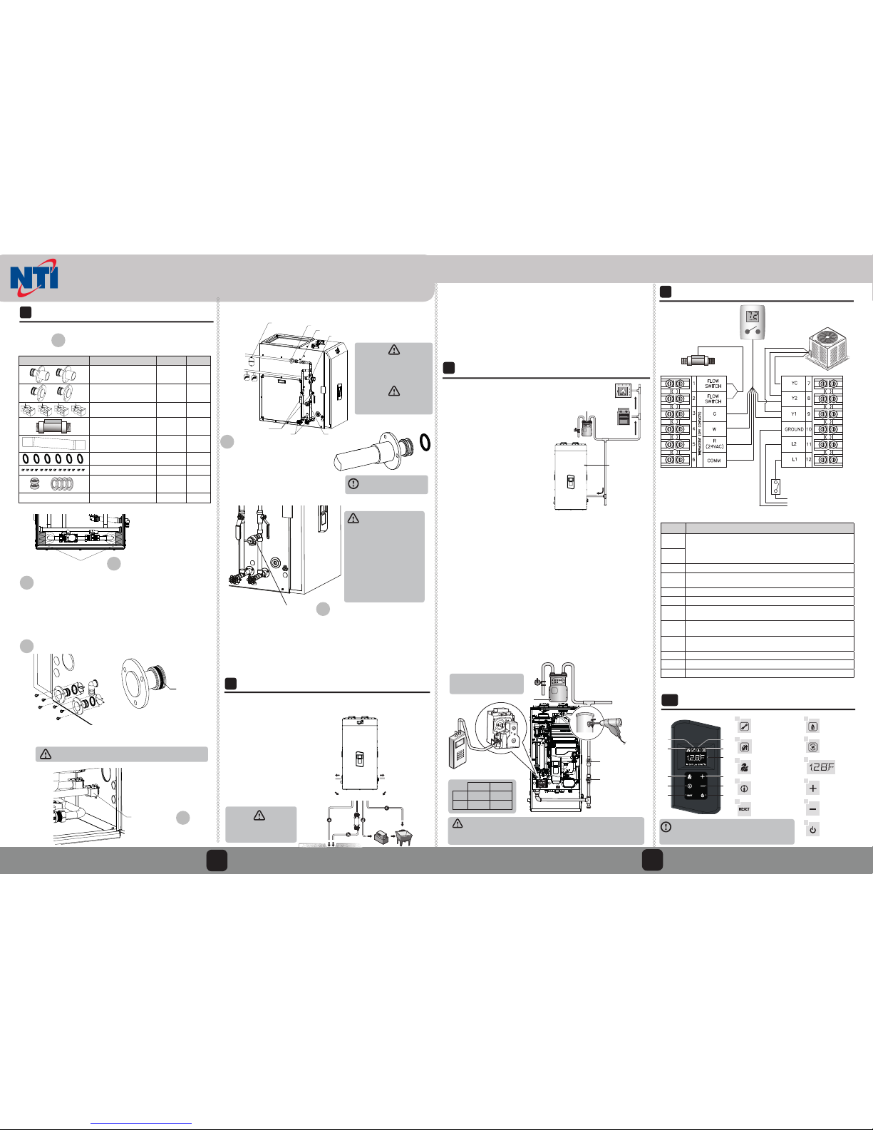
9
Wiring
Service switch
(Field Supplied)
120V /1P/60HZ
15A FUSED
POWER SUPPLY
a
b
c
d
e
f
g
h
i
j
k
a
b
c
d
e
f
g
h
i
j
k
Error
Hot Water Recirculation
Diagnostics button
Information button
Reset button
Combustion
N/A
Display
Up button
Down button
Power button
A code will appear
on the display
Indicates Recirculation
Mode or Pump activity
For installers only
A code will appear
on the display
Resets the water heater
(when an error occurs)
Indicates when the
gas burner is on
Increases the temperature
Decreases the temperature
Turns the water
heater on or o
10
Front Panel
8
Gas Connection
Pipe size : 1/2 in to 3/4 in
(inner diameter)
Gas Shuto Valve
Union
Gas Supply
Recommended Gas Pressure Settings:
NG: 3.5” – 10.5” w.c.
LP*: 8.0” – 13.0” w.c.
To connect the gas supply:
1. Determine the gas type and pressure for the appliance by referring to the rating plate.
2. Perform a pressure test on the main gas supply line. For detailed instructions to measure the inlet gas pressure, see relevant section in the water heater installation manual
(supplied).
3. Determine the proper size and type for the gas line. Purge the gas line of any debris.
4. Install full port valves on the gas supply line and appliance.
5. Connect the gas supply line. Test it, all connection points, and the GF200 for gas leaks.
6. Shut o manual gas valve and run a hot water faucet (until the water heater shuts o
due to lack of fuel) to purge the gas line.
7. Re-open the manual gas valve and open several high ow rate xtures to ramp the
water heater up to its maximum ring rate.
8. Check the inlet gas pressure reading on the manometer as shown below.
9. If readings are out of range: adjust the inlet gas pressure regulator.
Recommendation:
Install GF200 as
rst appliance
downstream of
meter
Gas Supply Line
Gas meter’s capacity ≥ Total gas
capacity of connected appliances
It is recommended that this appliance be connected as the rst one
downstream of the gas meter to
ensure a sucient gas supply.
●
Tighten the appliance connection
valves with care to avoid damage.
●
It is recommended that a union be
installed on the gas supply line close
to the appliance, to facilitate any
future maintenance or service.
●
Gas connection is possible from both
sides. A union inside the cabinet will
help improve access to plumbing
and lters when routing gas line
from right side.
NOTE:
Input Description
FLOW
SWITCH
FLOW SWITCH: Connect the two leads from the external ow switch here
(one per terminal). Note: The ‘hot’ lead only becomes energized (from the
H2Air board) when Central Heating mode (W) is active. Switch closes at
approx. 0.5 US gpm.
FLOW
SWITCH
W HEAT: Connect heating wire from thermostat here.
G
VENTILATION: Connect continuous ventilation / circulation wire from
thermostat here.
R 24 V AC OUTPUT: Connect power input wire from thermostat here.
C COMMON: Connect common wire from thermostat here.
YC
COMPRESSOR COMMON: Connect common wire from Outdoor A/C Unit
control here. This is the GF200 FREEZE PROTECTION – it must be connected.
Y2
COOLING (2nd Stage): Connect second stage cooling wire from thermostat
here (see Appendix 4.1 for cfm table).
Y1
COOLING (1st Stage): Connect rst stage cooling wire from thermostat here
(see Appendix 4.1 for cfm table).
GROUND GROUND: Connect earth ground wire here.
L2 NEUTRAL: Connect the neutral wire for the power supply here
L1 LINE: Connect the line voltage wire for the power supply here
Cold Water
Remove the kit box before installation.
Do not use metal pipe
for draining condensate
Combustion Settings (%CO ± 0.5):
High re Low re
NG
8.9 9.5
LP*
10.2 10.8
Combustion Analyzer (optional):
Each NPE-240A is factory-tested
before assembly into the GF200.
However, should you wish to verify
the combustion, target %CO values
are listed below.
NOTE: Master power switch located behind
the front cover on right-hand side of wiring
panel it must be ON to operate NPE-240A.
GF200
Quick Installation Guide
 Loading...