

Page 1
FTV Boiler
Model Numbers: FTV110, FTV110C, FTV150, FTV150C, FTV190 & FTV190C
Version Date: 2018-03-12
INSTALLATION AND OPERATION MANUAL
TABLE OF CONTENTS
HAZARD SYMBOLS AND DEFINITIONS
Danger Sign: Indicates a hazardous situation which, if not avoided, will
result in serious injury or death.
Warning Sign: Indicates a hazardous situation which, if not avoided,
could result in serious injury or death.
Caution Sign plus Safety Alert Symbol: Indicates a hazardous situation
which, if not avoided, could result in minor or moderate injury.
Caution Sign without Safety Alert Symbol: Indicates a hazardous
situation which, if not avoided, could result in property damage.
Notice Sign: Indicates a hazardous situation which, if not avoided,
could result in property damage.
This Boiler must be installed by a licensed and trained Heating
Technician or the Warranty is Void. Failure to properly install this
unit may result in property damage, serious injury to occupants, or possibly death.
H
NTI # 85939
Page 2

2
Warnings │ FTV I&O Manual
Read Before Proceeding
If you do not follow these instructions exactly, a fire or explosion may result causing
property damage, serious injury or death.
FOR YOUR SAFETY, READ BEFORE OPERATING_
A) This boiler does not have a pilot. It is equipped with an ignition device which automatically lights the
burner. Do not try to light the burner by hand.
B) BEFORE OPERATING smell all around the boiler area for gas. Be sure to smell next to the floor
because some gas is heavier than air and will settle on the floor.
WHAT TO DO IF YOU SMELL GAS:
• Do not try to light any boiler.
• Do not touch any electric switch.
• Do not use any phone in your building.
• Immediately call your gas supplier from a neighbor's phone. Follow the gas supplier's instructions.
• If you cannot reach your gas supplier, call the fire department.
C) Use only your hand to turn the gas “shutoff” valve. Never use tools. If the handle will not turn by hand,
do not try to repair it, call a qualified service technician. Force or attempted repair may result in a fire or
explosion.
D) Do not use this boiler if any part has been under water. Immediately call a qualified service technician
to inspect the boiler and to replace any part of the control system and any gas control which has been
under water.
OPERATING INSTRUCTIONS_
1. STOP! Read the safety information above very carefully.
2. Set the thermostat to lowest setting. Turn off all electric power to the boiler.
3. This boiler does not have a pilot. It is equipped with an ignition device which automatically lights the
burner. Do not try to light the burner by hand.
4. Turn the manual gas valve to the OFF position. Remove front access panel.
5. Wait five (5) minutes to clear out any gas. Then smell for gas, including near the floor. If you smell gas,
STOP! Follow “B” in the safety information above. If you do not smell gas, go to the next step.
6. Turn the manual gas valve ON. Wait an additional five (5) minutes smelling for gas.
7. Replace the front access panel.
8. Set thermostat to highest setting. Turn on all electric power to the boiler.
9. Ignition sequence is automatic. Combustion will occur after a brief fan purge.
10. If ignition does not occur, follow the instructions “To Turn Off Gas To Boiler” and call your service
technician or gas supplier.
TO TURN OFF GAS TO THE BOILER_
1. STOP! Read the safety information above very carefully.
2. Turn off all electric power to the boiler.
3. Turn the manual gas valve to the OFF position.
Crystalline Silica - Certain components confined in the combustion chamber may
contain this potential carcinogen. Improper installation, adjustment, alteration, service or
maintenance can cause property damage, serious injury (exposure to hazardous
materials) or death. Refer to Section 15.0 for information on handling instructions and
recommended personal protective equipment. Installation and service must be performed
by a qualified installer, service agency or the gas supplier (who must read and follow the
supplied instructions before installing, servicing, or removing this boiler. This boiler
contains materials that have been identified as carcinogenic, or possibly carcinogenic, to
humans).
Void Warranty - This Boiler must have water flowing through it whenever the burner is
on or it will damage the unit and void the warranty. Failure to follow these instructions
may result in serious injury or death.
Page 3
FTV I&O Manual │Introduction
3
Energy Saving Feature - This boiler is equipped with a feature that saves energy by
reducing the boiler water temperature as the heating load decreases. This feature is
equipped with an override which is provided primarily to permit the use of an external energy management
system that serves the same function. THIS OVERRIDE MUST NOT BE USED UNLESS AT LEAST ONE
OF THE FOLLOWING CONDITIONS IS TRUE :
An external energy management system is installed that reduces the boiler water temperature as the heating
load decreases.
This boiler is not used for any space heating.
This boiler is part of a modular or multiple boiler system having a total input of 300,000 BTU/hr. or greater.
This boiler is equipped with a tankless coil.
1.0 INTRODUCTION
General Installation Requirements
The installation of your NTI FTV gas boiler must conform to the requirements of this manual, your local
authority, and the National Fuel Gas Code ANSI Z223.1 and or CAN/CGA B149 Installation Codes. Where
required by the Authority, the installation must conform to the standard for “Controls and Safety Devices for
Automatically Fired Boilers ANSI/ASME CSD-1.”
This document pertains to the correct installation and operation of NTI FTV boiler models FTV110, FTV110C,
FTV150, FTV150C, FTV190 and FTV190C. The instructions detailed in this document supersede any and all
previous instructions provided by NTI, written or otherwise. Each unit is provided with the following:
1. Installation and Operation Manual,
2. User Information Manual, and
3. Natural Gas to LP Conversion Kit*
* The conversion kit is required to convert the boiler so it will safely operate with Propane Gas.
Read and understand this entire document prior to proceeding with the installation of the
FTV boiler. These instructions apply to all FTV models, but some specifically indicated
sections apply specifically to Combi models FTV110C, FTV150C and FTV190C due to
the built-in water heater. Failure to follow the instructions outlined in this document will
result in property damage, serious injury or death.
User Responsibilities
This boiler must be installed and serviced by a qualified installer or service technician. This boiler must be
serviced and inspected annually when operating in normal residential applications. Demanding applications or
extreme conditions (i.e. when operating with LP-Propane) may require more frequent service and inspection. As
the User/Owner of this equipment, you are responsible for ensuring the maintenance is performed at the required
intervals (see Section 16.0 – Annual Maintenance and Inspection).
Failure to have the boiler properly serviced and inspected on a regular basis by a qualified
service technician may result in property damage, serious injury or death.
Failure to keep the Vent and Combustion Air-intake clear of ice, snow, and other debris
may result in property damage, serious injury, or death.
Installer Responsibilities
As the installing technician it is your responsibility to ensure the installation is performed in accordance with this
instruction manual as well as any applicable local or National installation codes. It is also your responsibility to
inform the User/Owner of their obligation with respect to the above description under “User Responsibilities.”
Failure to follow this warning could result in fire, serious injury, or death.
Page 4
Introduction │ FTV I&O Manual
4
ATTENTION: LIQUEFIED PETROLEUM (LP) PROPANE
Liquefied Petroleum (LP) propane gas is heavier than air; therefore, it is imperative that your FTV boiler is not
installed in a pit or similar location that will permit heavier than air gas to collect. Local Codes may require
boilers fueled with LP gas be provided with an approved means of removing unburned gases from the room.
Check your local codes for this requirement.
Natural Gas to LP Conversion Kit
Model
Natural Gas to LP Conversion Kit (part no.)
LP-Venturi Insert (part no.)
FTV110 & FTV110C
85995-1
85989
FTV150 & FTV150C
85446-1
85536
FTV190 & FTV190C
85934-1
85812
Note:
FTV models are converted to Propane using a replacement LP-Venturi Insert, not by installing an orifice. Follow the
Natural Gas to LP Conversion Instructions provided with the Kit.
FTV boilers are factory set to operate with Natural Gas; BEFORE OPERATING
WITH PROPANE, the boiler must be converted using the appropriate Natural Gas to
LP Conversion Kit; see below. Failure to properly convert the unit to safely operate with
Propane will cause dangerous burner operation, resulting in property damage, serious
injury or death.
Exhaust Vent / Air-Inlet Piping
The FTV is certified as a “Category IV” boiler, and require a “Special Venting System”
designed for pressurized venting. The exhaust gases must be piped directly to the
outdoors using the vent materials and rules outlined in these instructions. Failure to
follow these instructions will result in serious injury or death.
Page 5
5
IN THE STATE OF MASSACHUSETTS ONLY
(a) For all horizontally vented gas fueled equipment installed in every dwelling, building or structure used in whole or
in part for residential purposes, including those owned and operated by the Commonwealth and where the side wall
exhaust vent termination is less than seven (7) feet above finished grade in the area of the venting, including but not
limited to decks and porches, the following requirements shall be satisfied:
1. INSTALLATION OF CARBON MONOXIDE DETECTORS At the time of installation of the side wall
horizontal vented gas fueled equipment, the installing plumber or gas fitter shall observe that a hard wired
carbon monoxide detector with an alarm and battery back-up is installed on the floor level where the gas
equipment is to be installed and on each additional level of the dwelling, building or structure served by the
equipment. It shall be the responsibility of the property owner to secure the services of qualified licensed
professionals for the installation of hard wired carbon monoxide detectors.
a. In the event that the side wall horizontally vented gas fueled equipment is installed in a crawl space or an
attic, the hard wired carbon monoxide detector with alarm and battery back-up may be installed on the next
adjacent floor level.
b. In the event that the requirements of this subdivision cannot be met at the time of completion of
installation, the owner shall have a period of 30 days to comply with the above requirements; provided,
however, that during said 30 day period a battery operated carbon monoxide detector with an alarm shall
be installed.
2. APPROVED CARBON MONOXIDE DETECTORS Each carbon monoxide detector as required in accordance
with the above provisions shall comply with NFPA 720 and be ANSI/UL 2034 listed and IAS certified.
3. SIGNAGE A metal or plastic identification plate shall be permanently mounted to the exterior of the building
at a minimum height of eight (8) feet above grade directly in line with the exhaust vent terminal for the
horizontally vented gas fueled heating boiler or equipment. The sign shall read, in print size no less than onehalf (1/2) inch in size, “GAS VENT DIRECTLY BELOW. KEEP CLEAR OF ALL OBSTRUCTIONS”
(plate included with boiler).
4. INSPECTION The state or local gas inspector of the side wall horizontally vented gas fueled equipment shall
not approve the installation unless, upon inspection, the inspector observes carbon monoxide detectors and
signage installed in accordance with the provisions of 248 CMR 5.08(2)(a)1 through 4.
(b) EXEMPTIONS: The following equipment is exempt from 248 CMR 5.08(2)(a)1 through 4:
1. The equipment listed in Chapter 10 entitled “Equipment Not Required To Be Vented” in the most current
edition of NFPA 54 as adopted by the Board; and
2. Product Approved side wall horizontally vented gas fueled equipment installed in a room or structure separate
from the dwelling, building or structure used in whole or in part for residential purposes.
(c) MANUFACTURER REQUIREMENTS – GAS EQUIPMENT VENTING SYSTEM PROVIDED: When the
manufacturer of Product Approved side wall horizontally vented gas equipment provides a venting system design or
venting system components with the equipment, the instructions provided by the manufacturer for installation of the
equipment and the venting system shall include:
1. Detailed instructions for installation of the venting system design or the venting system components; and
2. A complete parts list for the venting system design or venting system.
(d) MANUFACTURER REQUIREMENTS – GAS EQUIPMENT VENTING SYSTEM NOT PROVIDED:
When the manufacturer of a Product Approved side wall horizontally vented gas fueled equipment does not provide
the parts for venting the flue gases, but identifies “special venting systems,” the following requirements shall be
satisfied by the manufacturer:
1. The referenced “special venting system” instructions shall be included with the appliance or equipment
installation instructions; and
2. The “special venting system” shall be Product Approved by the Board, and the instructions for that system shall
include a parts list and detailed installation instructions.
(e) A copy of all installation instructions for all Product Approved side wall horizontally vented gas fueled equipment,
all venting instructions, all parts list for venting instructions, and/or all venting design instructions shall remain with
the appliance or equipment at the completion of the installation.
FTV I&O Manual │Introduction
Page 6
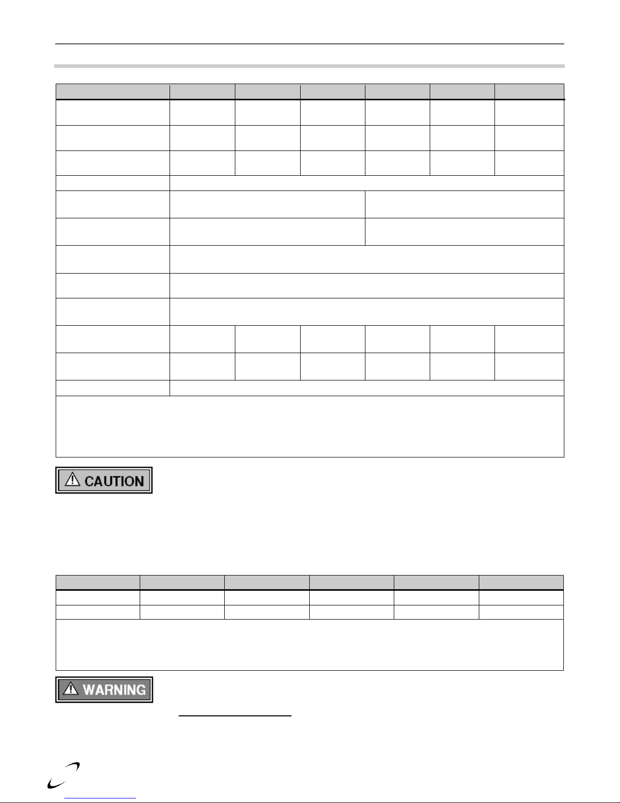
Specifications │ FTV I&O Manual
6
DESCRIPTION
FTV110
FTV150
FTV190
FTV110C
FTV150C
FTV190C
CSA Input Modulation
[MBH] 1
11 - 110
15 - 150
19 - 190
11-110
15 - 150
19 - 190
DOE Heating Capacity
[MBH]
1,2
101
138
176
101
138
176
Net I=B=R Rating
[MBH]
1,2
88
120
153
88
120
153
DOE AFUE [%] 2
95
Boiler Water
Connections – NPT [in.]
1” (Male)
3/4” (Male)
DHW Connections –
NPT [in.]
NA
3/4” (Male)
Gas Connection – NPT
[in.]
1/2” (Female)
Vent/Air-inlet
Connections [in.] 3
3
Dimensions H x W x D
[in.]
37.25 x 19.5 x 18.5
Approx. Boiler Weight
with Water [lbs.]
100
115
140
110
125
150
Approx. Boiler Water
Content [Gallons]
1.4
2.0
2.7
1.4
2.0
2.7
Electrical Rating
120V/1Ph/60Hz/less than 12A
Notes:
1
Listed Input and Output ratings are at minimum vent lengths using 3” venting, at an altitude of 0-2000 ft. Numbers will
be lower with longer venting and/or altitudes greater than 2000 ft.
2
Ratings based on standard test procedures prescribed by the U.S. Department of Energy.
3
FTV boilers require a special venting system, use only vent materials and methods detailed in these instructions.
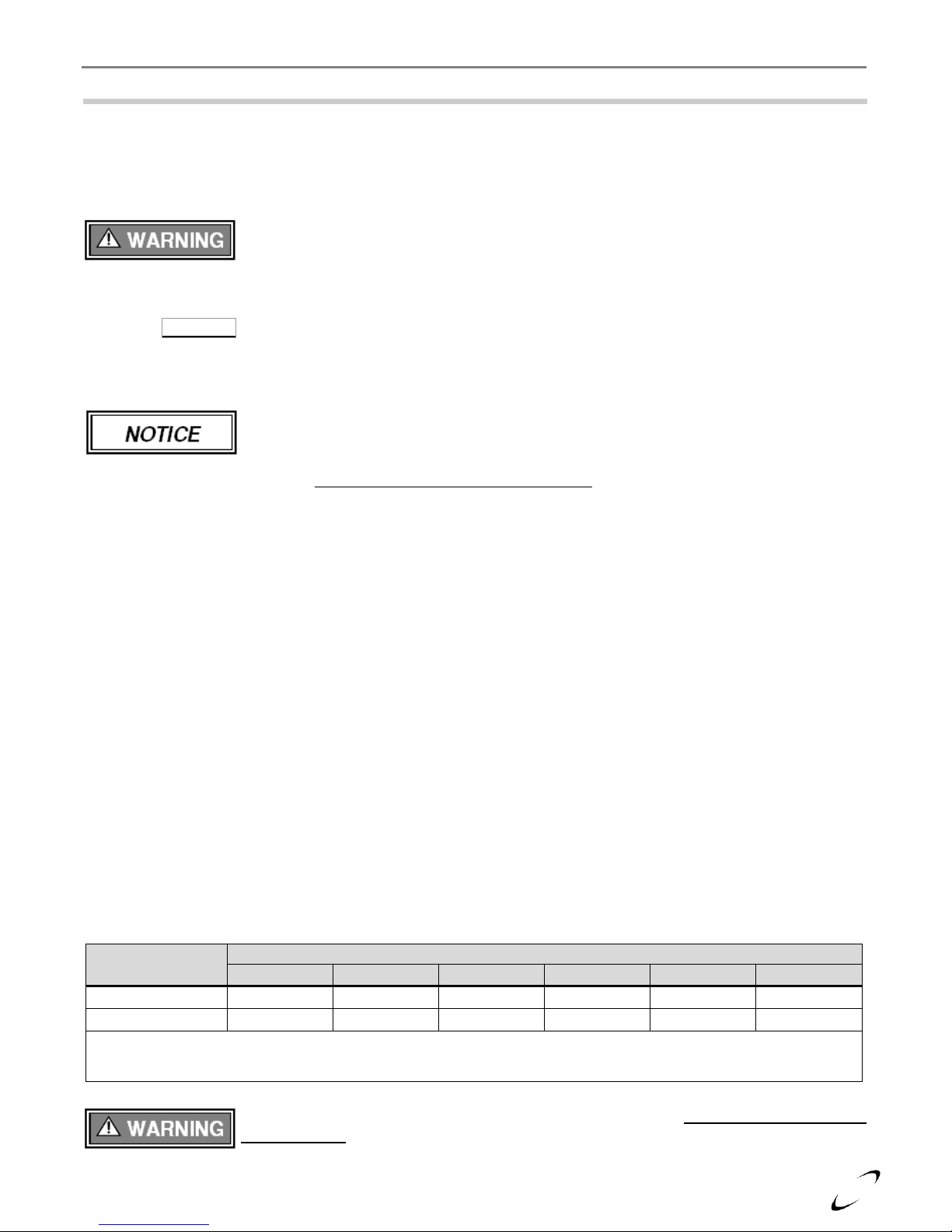
Elevations
2001 ft [610 m]
3000 ft [914 m]
4000 ft [1219 m]
4500 ft [1372 m]
5000 ft [1524 m]
In Canada 1
de-rate by 10%
de-rate by 10%
de-rate by 10%
de-rate by 10%
de-rate % may vary
In USA 2
-
de-rate by 12%
de-rate by 16%
de-rate by 18%
de-rate by 20%
Notes:
1
Canada: Altitudes between 2000-4500 ft [610-1372 m], de-rate by 10%. Consult local authorities for de-rating for
altitudes above 4500ft [1372 m].
2
USA: De-rate capacity by 4% for every 1000 ft [305 m], if altitude is above 2000 ft [610 m].
2.0 SPECIFICATIONS
Table 2-1 FTV Specifications
Wall mounting of unit requires two people to lift the boiler into place. Failure to follow
these instructions may result in property damage or personal injury.
High Altitude Operation
The FTV is designed to operate at its maximum listed capacity in installations located at 0-2000 ft above Sea
Level. Since the density of air decreases as elevation increases, maximum specified capacity should be de-rated
for elevations above 2000 ft [610 m] in accordance with Table 2-2.
Table 2-2 De-rate % for High Altitudes
Combustion – At elevations above 2000 feet, the combustion of the boiler must be
checked with a calibrated combustion analyzer to ensure safe and reliable operation. It is
the Installers responsibility to check the combustion and to adjust the combustion
in accordance with Section 9.0. Failure to follow these instructions may result in
property damage, serious injury, or death.
Page 7
7
Clearances
Dimensions – inches
Front
Top
Sides
Back
Bottom
Flue Pipe
Minimum
24 1
12 4 0 9 1
Recommended
36
24
12 0 24
1
Notes:
1
6 in. if surface is removable allowing a minimum of 24 in. clearance (i.e. closet installation). See Ventilation Air
Opening dimensions in Figure 3-1.
FTV I&O Manual │Boiler Location
3.0 BOILER LOCATION
In all cases, the FTV boiler must be installed indoors in a dry location where the ambient temperature must be
maintained above freezing and below 100F [38C]. All boiler components must be protected from dripping,
spraying water, or rain during operation and servicing. Consider the proximity of system piping, gas and
electrical supply, condensate disposal drain, and proximity to vent termination when determining the best boiler
location.
Boiler Area Ventilation Air Openings
If boiler area clearances are less than the recommended clearances specified in Table 3-1, the boiler area must be
ventilated (Exception: if the boiler area/room has a volume of 150 ft3 or greater, ventilation of the boiler room is
not required). Each ventilation air opening must meet the minimum requirements of 1 in2 per 1000 Btu/hr., but
not less than 100 in2. The lower ventilation opening must be located within 6 in. of the floor while the upper
opening must be located 6 in. from the top of the space.
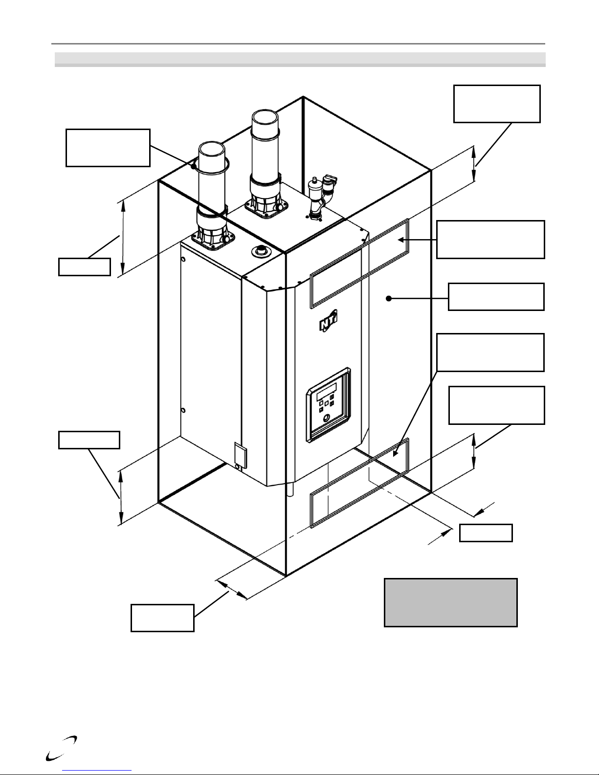
Closet Installations
For closet installations it is necessary to provide two ventilation air openings as shown in Figure 3-1, each
providing a minimum area equal to 1 in2 per 1000 Btu/hr., but not less than 100 in2 and within 6 in. of the top
and bottom of the closet door. See Table 3-1 for minimum clearances.
Alcove Installations
Alcove installations have the same minimum clearances as closet installations, except the front must be
completely open to the room at a distance no greater than 18 in. [457 mm] from the front of the boiler and the
room is at least three (3) times the size of the alcove. Provided these conditions are met, the boiler requires no
extra ventilation air openings to the space. See Table 3-1 for minimum clearances.
Residential Garage Installations
When installed in a residential garage, mount the boiler a minimum of 18 in. [457 mm] above the floor. Locate
or protect the boiler so it cannot be damaged by a moving vehicle. Check with your local authorities for other
possible regulations pertaining to the installation of a boiler in a garage.
Wall Mounting Installations
FTV boilers are provided with integrated wall mounting brackets. Refer to Figure 3-2 for instructions and
illustrations on wall mounting.
Table 3-1 Minimum Clearances for Installation and Service
Water or flood damaged components must be replaced immediately with new factoryapproved components as failure to do so may result in fire, serious injury, or death.
If the "Boiler Area" does not meet the recommended clearances listed in Table 3-1, and if
the boiler area has a volume less than 150 ft3, it is considered a Closet or Alcove. In
US/Canada, PVC vent pipe and fittings shall not be used within the closet or alcove; only
approved CPVC, Polypropylene or Stainless Steel vent pipe and fittings can be used. See
Table 4-5 for a list of approved materials. Under all circumstances, the minimum
clearances listed in Table 3-1 must be provided.
Closet/Alcove installations in US and Canada require approved CPVC, Polypropylene or
Stainless Steel vent and air-inlet pipe and fittings (see Table 4-5); PVC is not permitted.
Failure to follow these instructions may result in damage or serious injury.
Page 8
8
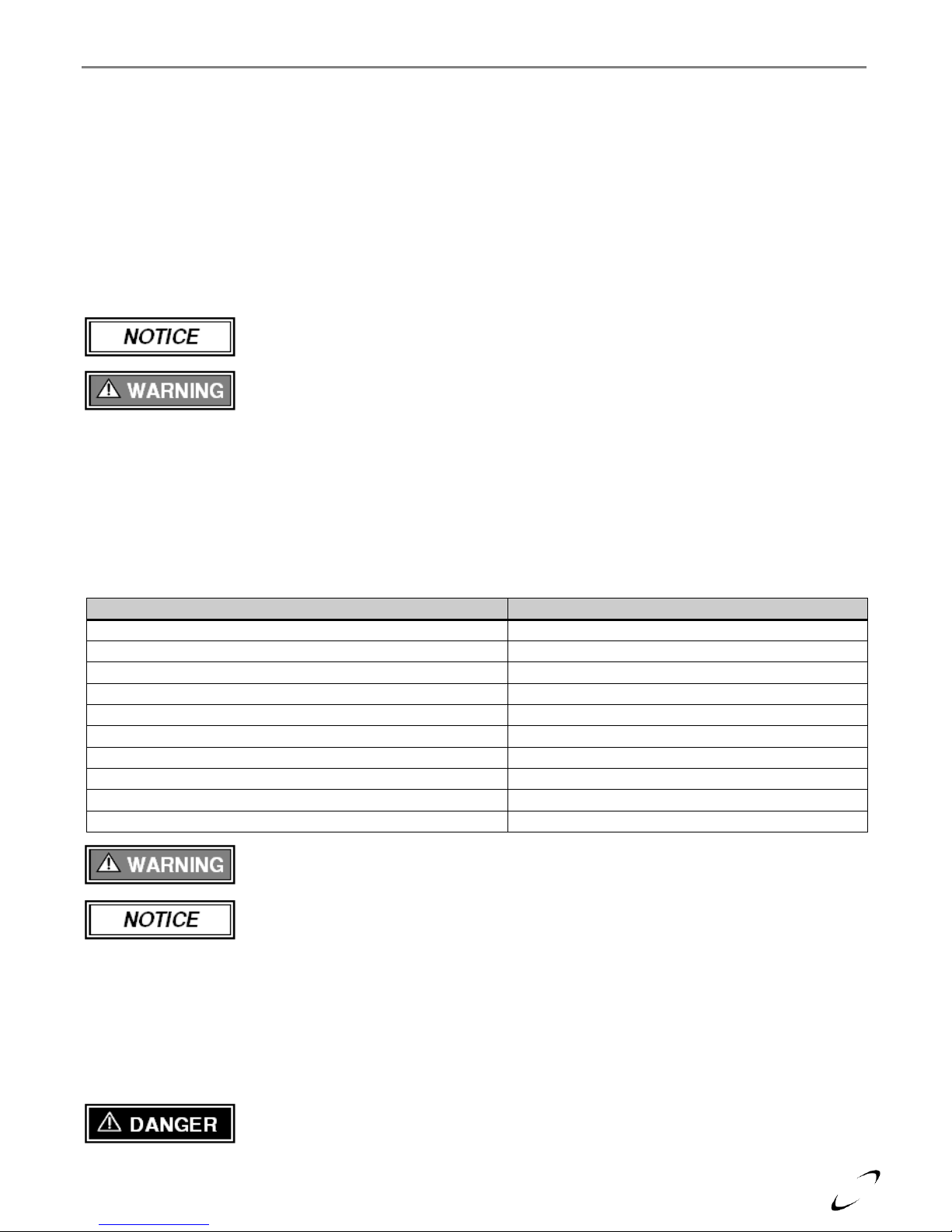
Figure 3-1 Closet Installation, Minimum Clearances
Ventilation Air Openings are
not required if the boiler area
meets the Recommended
Clearances listed in Table 3-1.
Top ventilation
opening Max. 6”
below ceiling / top
Ventilation air opening
1in2 per 1000 Btu/hr,
min. 100in
2
Removable surface /
closet door
Ventilation air opening
1in2 per 1000 Btu/hr,
min. 100in
2
Bottom ventilation
opening Max. 6”
above floor / bottom
Sides = 4”
Top = 12”
Bottom = 9”
Min. 1” clearance
for hot water and
vent pipes
Front = 6”
(if removable)
Boiler Location │ FTV I&O Manual
Page 9
9
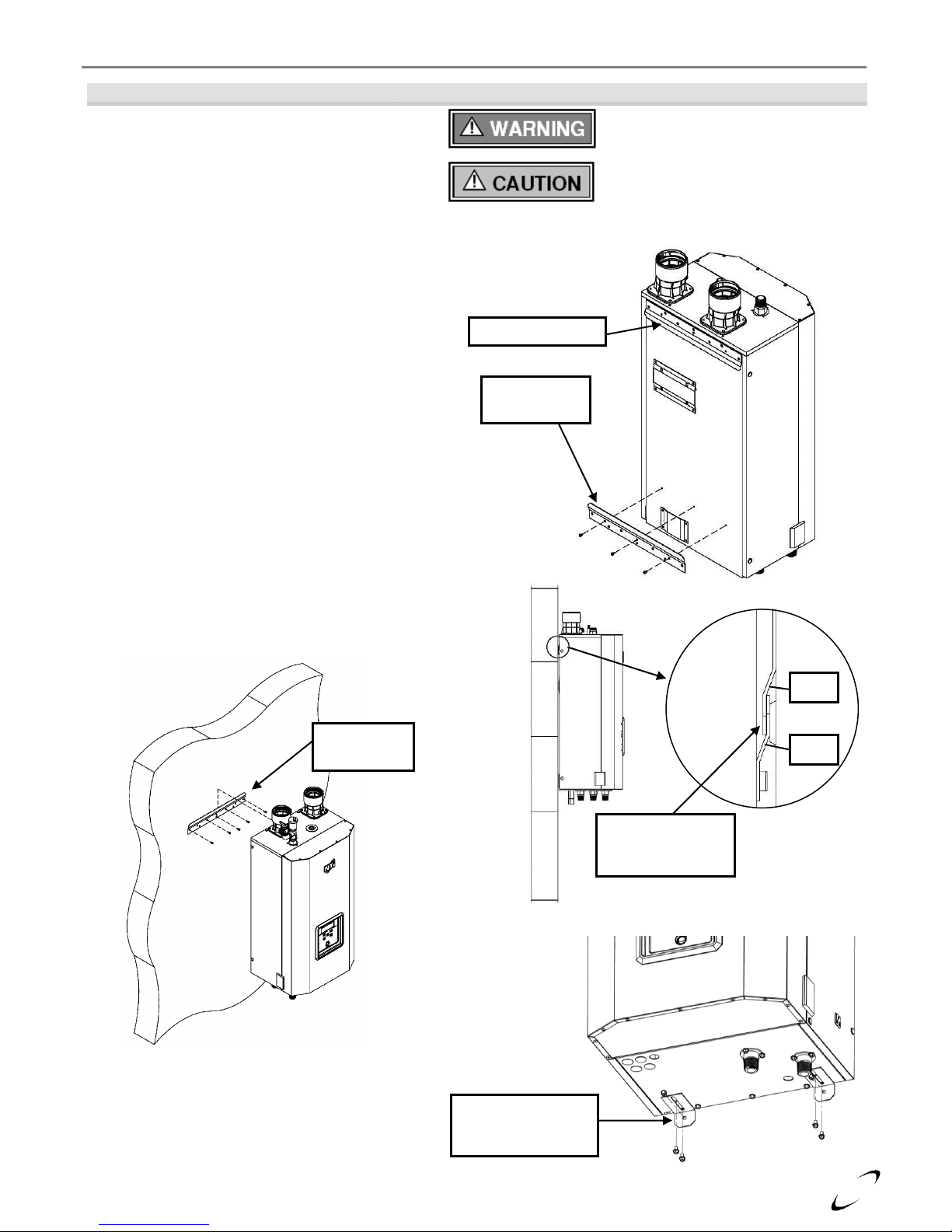
Figure 3-2 Wall Mounting Instructions
Leave the Top Wall-mount Bracket (A) intact
and remove the Bottom Wall-mount Bracket
(B) that is attached to the bottom-back of the
boiler.
Secure Bottom Bracket (B), removed from the
bottom back of the boiler in Step 1, to a solid
wall using field supplied lag screws (anchors
when mounting to a concrete wall) that are
adequate to support the weight of the appliance
when filled with water (refer to Table 2-1
Specifications). Ensure the bracket is level and
flush to the wall. Mounting holes to be on the
bottom with flange pointed upward and angled
away from the wall.
Mount the boiler to the wall by aligning the
two wall mount brackets, Top Bracket (A)
with the Bottom bracket (B). Slide the top
bracket fastened to the boiler down over the
wall-mounted bracket until it hooks.
Once the boiler is resting securely on the wall,
attach the L-shaped Brackets (C) to the
underside of the appliance using the mounting
hardware supplied in the boiler kit box – adjust
to plumb the boiler. Anchor the L-shaped
Brackets (C) to the wall as shown using field
supplied hardware.
Failure to follow instructions may
result in fire, serious injury, or death.
This unit requires two people to lift it
or damage and injury may result.
Bottom
Bracket (B)
Wall
Boiler
Ensure Bracket
(A) fully inserts
into Bracket (B)
(B)
(A)
Top Bracket (A)
Bottom
Bracket (B)
L-shaped Brackets
(C) shipped with
boiler kit box
FTV I&O Manual │Boiler Location
Page 10

10
General Venting │ FTV I&O Manual
4.0 GENERAL VENTING
The FTV is certified as a “Category IV” boiler requiring a “Special Venting System” designed for pressurized
venting. The Exhaust Vent must be piped to the outdoors, using the vent materials and rules outlined in this
section. Under no conditions may this unit vent gases into a masonry chimney, unless it is vacant, and utilizes the
approved venting material and rules described in this section.
Removing an Existing Boiler from Common Venting System
Upon removal of an existing boiler, the following steps shall be followed for each boiler remaining in the
common venting system; prior to commencing this procedure, shutdown all boilers remaining in the common
venting system.
Steps to Removing an Existing Boiler:
1. Seal any unused openings in the common venting system.
2. Visually inspect the venting system for proper size and horizontal pitch. Verify that there is no blockage,
restriction, leakage, corrosion or other deficiencies which could cause an unsafe condition.
3. Insofar as is practical, close fireplace dampers, all building doors and windows and all doors between the
space in which the boilers remaining connected to the common venting system are located and other spaces
of the building. Turn on clothes dryers and any boiler not connected to the common venting system. Turn on
any exhaust fans, such as range hoods and bathroom exhausts, so they will operate at maximum speed. Do
not operate a summer exhaust fan.
4. Place in operation the boiler being inspected. Follow the applicable lighting instructions. Adjust thermostat
so boiler will operate continuously.
5. Test for spillage at the draft hood relief opening after 5 minutes of main burner operation. Use the flame of a
match or candle, or smoke from a cigarette, cigar or pipe.
6. After it has been determined that each boiler remaining connected to the common venting system properly
vents when tested as outlined above, return doors, windows, exhaust fans, fireplace dampers and any other
gas burning boiler to their previous condition of use.
7. Any improper operation of the common venting system should be corrected so the installation conforms to
the National Fuel Gas Code, ANSI Z223.1/NFPA 54 and/or CAN/CSA B149.1, Natural Gas and Propane
Installation Code. When resizing any portion of the common venting system, the common venting system
should be resized to approach the minimum size as determined using the appropriate tables in Part 11 of the
National Fuel Gas Code, ANSI Z223.1/NFPA 54 and/or CAN/CSA B149.1, Natural Gas and Propane
Installation Code.
Vent and Air-inlet are to be piped separately. The FTV cannot share a common vent or
air-inlet with multiple boilers. Failure to comply will result in serious injury or death.
Do not install the FTV into a common venting system with any other boiler. Failure to
comply with this warning will cause flue gas spillage and leech carbon monoxide
emissions into the surrounding air resulting in serious injury or death.
When an existing boiler is removed from a common venting system, the common venting
system is likely to be too large for proper venting of the remaining boilers connected to
it. Instructions have been provided on how to remove the existing boiler and how to
resize the remaining venting system. Failure to follow these instructions may result in
property damage, serious injury or death.
Page 11
11
Products to Avoid
Contaminated Sources to Avoid
Antistatic fabric softeners, bleaches, detergents, cleaners
Laundry facilities
Perchloroethylene (PCE), hydrocarbon based cleaners
Dry cleaning facilities
Chemical fertilizer, herbicides/pesticides, dust, methane gas
Farms or areas with livestock and manure
Paint or varnish removers, cements or glues, sawdust
Wood working or furniture refinishing shops
Water chlorination chemicals (chloride, fluoride)
Swimming pools, hot tubs
Solvents, cutting oils, fiberglass, cleaning solvents
Auto body or metal working shops
Refrigerant charge with CFC or HCFC
Refrigerant repair shops
Permanent wave solutions
Beauty shops
Fixer, hydrochloric acid (muriatic acid), bromide, iodine
Photo labs, chemical / plastics processing plants
Cement powder, crack fill dust, cellulose, fiber based insulation
Concrete plant or construction site
FTV I&O Manual │General Venting
Direct Vent Installation (Best Practice)
When installed as a Direct Vent boiler the combustion air-inlet must also be piped directly to the outdoors using
the methods described in this section and in accordance with the National Fuel Gas Code, ANSI Z223.1 (U.S.) or
CSA B149.1 (Canada) and local requirements.
Installation Using Indoor Combustion Air
When the installation uses Indoor Combustion Air (i.e. piping is not directly connecting the appliance air-inlet
fitting to the outdoors), provisions for combustion and ventilation air, in accordance with section “Air for
Combustion and Ventilation,” of the National Fuel Gas Code, ANSI Z223.1/NFPA 54 (U.S.), or Clause 8.2, 8.3
or 8.4 of Natural Gas and Propane Installation Code, CAN/CSA B149.1 (Canada), or applicable provisions of
the local building codes, must be adhered to.
The boiler shall be located so as not to interfere with proper circulation of combustion,
ventilation, and dilution air.
Make up air requirements for the operation of exhaust fans, kitchen ventilation systems,
clothes dryers, and fireplaces shall be considered in determining the adequacy of a space
to provide combustion air requirements. Failure to ensure adequate make up air to all
appliances may result in personal injury or death.
Combustion Air-inlet Contamination
Be careful not to locate the air-inlet termination in an area where contaminants can be drawn in and used for
combustion. Combustion air containing dust, debris or air-borne contaminants will drastically increase the
required maintenance and may cause a corrosive reaction in the Heat Exchanger which could result in premature
failure, fire, serious injury, or death. See Table 4-1 for a list of areas to avoid when terminating air-inlet piping:
Table 4-1 Corrosive Products and Contaminant Sources
Do not store or use gasoline or other flammable vapors and liquids in the vicinity of this
or any other boiler. Failure to follow instructions may result in serious injury or death.
It is BEST PRACTICE to pipe the combustion air-inlet directly to the outdoors (Direct
Vent installation) to avoid contamination often contained in indoor air.
Flammable Solvents and Plastic Piping
Due to the extremely flammable characteristics of most glues, cements, solvents and primers used in the process
of joining plastic vent and air-inlet pipe, explosive solvent vapors must be evacuated from the vent and air-inlet
prior to start-up. Avoid using excess cement or primer that may lead to pooling inside the pipe assembly. Freshly
assembled piping assembly should be allowed to cure for a minimum of 8 hours before applying power to the gas
fired boiler. Refer to Mandatory Pre-commissioning Procedure for Plastic Venting in this section.
Flammable Cements and Primers – It is the installers’ responsibility to familiarize
themselves with the hazards associated with explosive solvents and to take all precautions
to reduce these risks. Failure to follow these instructions can cause explosions, property
damage, injury or death.
Page 12
12
General Venting │ FTV I&O Manual
Mandatory Pre-commissioning Procedure for Plastic Venting (PVC or CPVC)
Do not apply power to the boiler prior to Step 4 in the Mandatory Pre-commissioning
Procedure for Plastic Venting.
1) Working with the power turned off to the boiler, completely install the vent and air-intake system, securely
cementing joints together. If possible, allow primers/cements to cure for 8 hours before firing the burner. If
curing time is less than 8 hours, proceed with Steps 2 through 6.
2) Maintain the boiler gas supply shut-off valve in the off position.
3) Remove the cable from the Spark Ignition Electrode and Ignition Controller.
Spark Ignition Circuit - Maintain a safe distance (2 in. minimum) from the spark ignition
circuit to avoid injury from electrical shock.
4) Turn power on to the boiler and apply a heat demand.
5) Allow for 5 complete trials for ignition, consisting of pre and post purge of the combustion blower, until an
ignition lockout occurs. Repeat the process one more time (i.e. 10 complete ignition sequences in total).
6) Turn power off and reconnect the cable to the Spark Ignition Transformer.
Near Boiler Vent/Air-inlet Piping
The FTV employs universal Exhaust-vent and Air-inlet appliance adapters that accept 3 in. PVC/CPVC,
Polypropylene (PP) or FasNSeal Stainless Steel (SS) piping, without the need for additional adapters. The
universal adapters incorporate three seals, one for 3 in. PVC/CPVC pipe (3.5 in. OD), one for 3 in. PP pipe (3.15
in. OD) and one for 3 in. FasNSeal SS pipe (3 in. OD). See Figure 4-2(a) for gasket identification and pipe
insertion depth based on pipe material used. Prior to inserting the piping into the universal adapter, ensure it is
properly bevel (approximately 1/8 in.) to avoid damaging or dislodging the sealing gasket during installation; see
Figure 4-2(b).
Gasket Seating - Improper seating can cause leakage and eventual failure of the sealing
gasket. Ensure the vent pipe is properly beveled, prior to installation, and that the pipe is
fully inserted into universal appliance adapter. Failure to follow these instructions may
result in serious injury or death.
PVC/CPVC Piping – Ensure the upper gasket of the universal appliance adapter is in place and properly
positioned prior to installation. Ensure the venting system does not apply a load or strain on the boiler flue
outlet adapter; recommend using two elbows to create a “swing joint” to reduce potential strain on vent piping
and cemented joints. When exhaust venting with PVC, use the supplied 5” long CPVC Transition Pipe
provided with the boiler; insert the CPVC pipe into the exhaust adapter and cement the other end to the PVC
exhaust venting using a field supplied PVC or CPVC coupling. See Figures 4-3(a) and 4-3(b).
PVC Exhaust Venting – DO NOT insert PVC pipe directly into the appliance exhaust
adapter, as it can deform from the clamping force of the gear clamp. Failure to follow
these instructions may result in gasket failure and/or the dislodging of the exhaust pipe
from the appliance adapter, resulting in property damage, serious injury or death.
PP Piping – Ensure the middle gasket of the universal appliance adapter is in place and properly positioned
prior to installation. Ensure the venting system does not apply a load or strain on the boiler flue outlet adapter;
recommend using an elbow with an offset to reduce potential strain on vent piping and cemented joints. See
Figure 4-3(c).
Stainless Steel Piping – The FTV universal appliance adapter is designed to connect directly to DuraVent –
FasNSeal AL29-4C Stainless Steel Special Gas Vent. Ensure the lower gasket of the universal appliance
adapter is in place and properly positioned prior to installation. Ensure the venting system does not apply a
load or strain on the boiler flue outlet adapter; recommend using two elbows to create a “swing joint” to
reduce potential strain on vent piping and cemented joints. See Figure 4-3(d).
Exhaust venting must be supported to reduce strain on piping joints. Failure to follow
these instructions may result in result in damage, serious injury or death.
In Canada, the first 3 ft (915 mm) of vent piping must be readily accessible for inspection.
Page 13
13
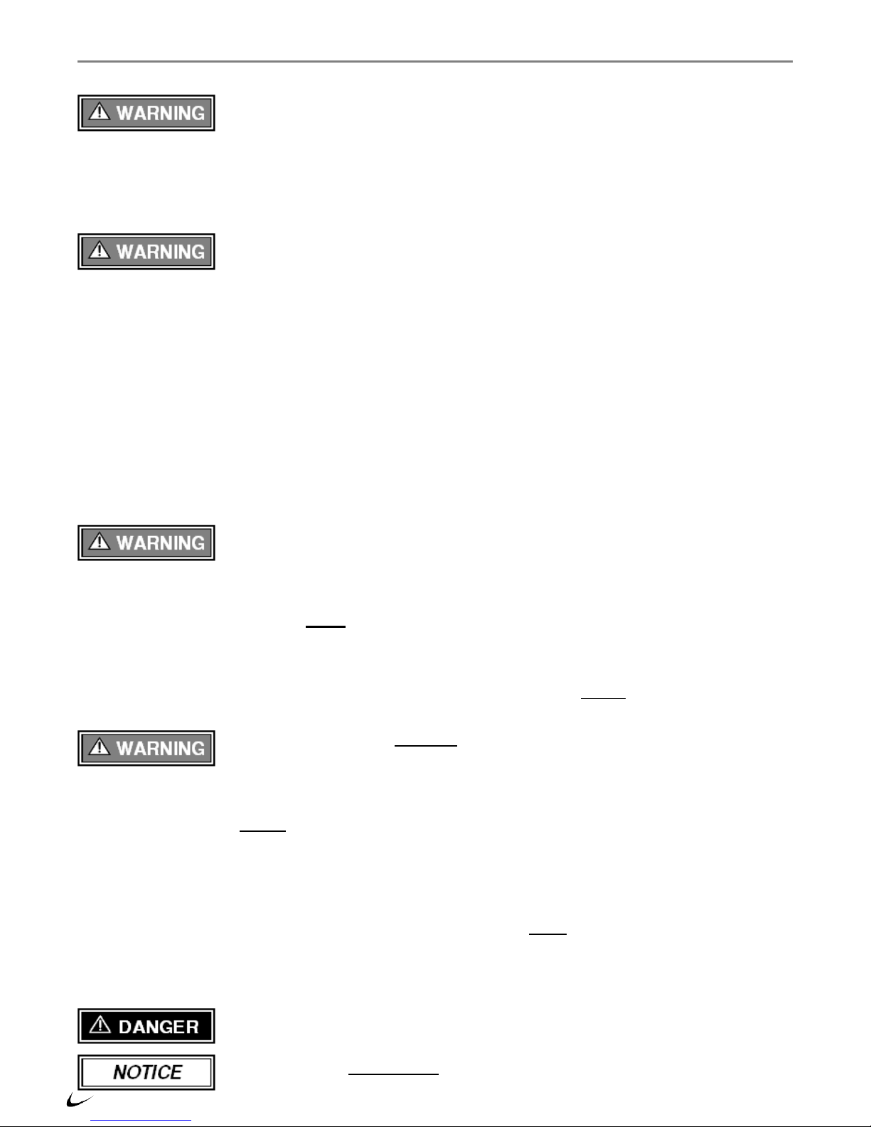
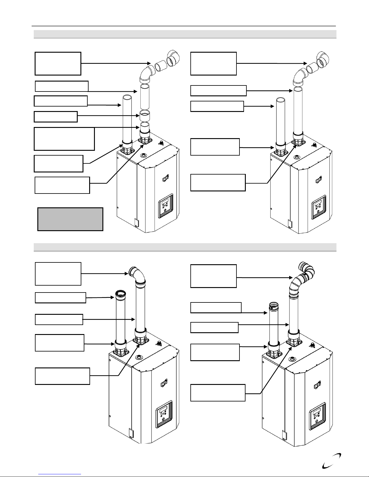
Figure 4-2 (a) Universal Appliance Adapter – Pipe Insertion Depth
Figure 4-2 (b) Exhaust Vent Connection – FTV110(C)
Figure 4-2 (c) Exhaust Vent Connection – FTV150-190(C)
Lower Gasket – 3” OD Seal
use with Stainless Steel
Middle Gasket – 3.14” OD Seal
use with Polypropylene
Upper Gasket – 3.5” OD Seal
use with CPVC (PVC for Air-inlet)
2.36” (CPVC/PVC)
3.46” (PP)
4.17” (SS)
CPVC/PP/SS Exhaust Pipe
With 1/8” bevel to prevent damage
to gasket. When venting with PVC,
use 5” long CPVC Transition Pipe
(factory supplied)
Exhaust-Vent
Adapter
Air-inlet Adapter
Tighten Gear Clamp after
fully inserting piping
CPVC/PP/SS Exhaust Pipe
With 1/8” bevel to prevent damage
to gasket. When venting with PVC,
use 5” long CPVC Transition Pipe
(factory supplied)
Exhaust-Vent
Adapter
Air-inlet Adapter
Tighten Gear Clamp after
fully inserting piping
FTV I&O Manual │General Venting
Page 14
14
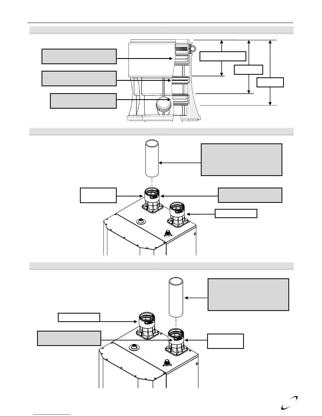
Figure 4-3(a) FTV110(C)
Figure 4-3(b) FTV110(C)
Near Boiler Venting (PVC)
Near Boiler Venting (CPVC)
Figure 4-3(c) FTV110(C)
Figure 4-3(d) FTV110(C)
Near Boiler Venting (PP)
Near Boiler Venting (SS)
Swing Joint
to attain slope in
horizontal runs
CPVC Transition Pipe
**minimum 5” long
(factory supplied)
Flue Outlet Adapter
(factory supplied)
**CPVC Transition Pipe
is mandatory when
venting with PVC
PVC Coupling
Air-inlet Adapter
(factory supplied)
PVC Air-inlet Pipe*
PVC Exhaust Vent
Swing Joint
to attain slope in
horizontal runs
Flue Outlet Adapter
(factory supplied)
Air-inlet Adapter
(factory supplied)
PVC Air-inlet Pipe*
CPVC Exhaust Vent
PP Elbow w.
offset angle to
account for slope
Flue Outlet Adapter
(factory supplied)
Air-inlet Adapter
(factory supplied)
PP Air-inlet Pipe*
PP Exhaust Vent
Swing Joint
to attain slope in
horizontal runs
Flue Outlet Adapter
(factory supplied)
Air-inlet Adapter
(factory supplied)
SS Air-inlet Pipe
SS Exhaust Vent
General Venting │ FTV I&O Manual
Air-inlet - check with applicable local codes for acceptable pipe material.
Page 15
15
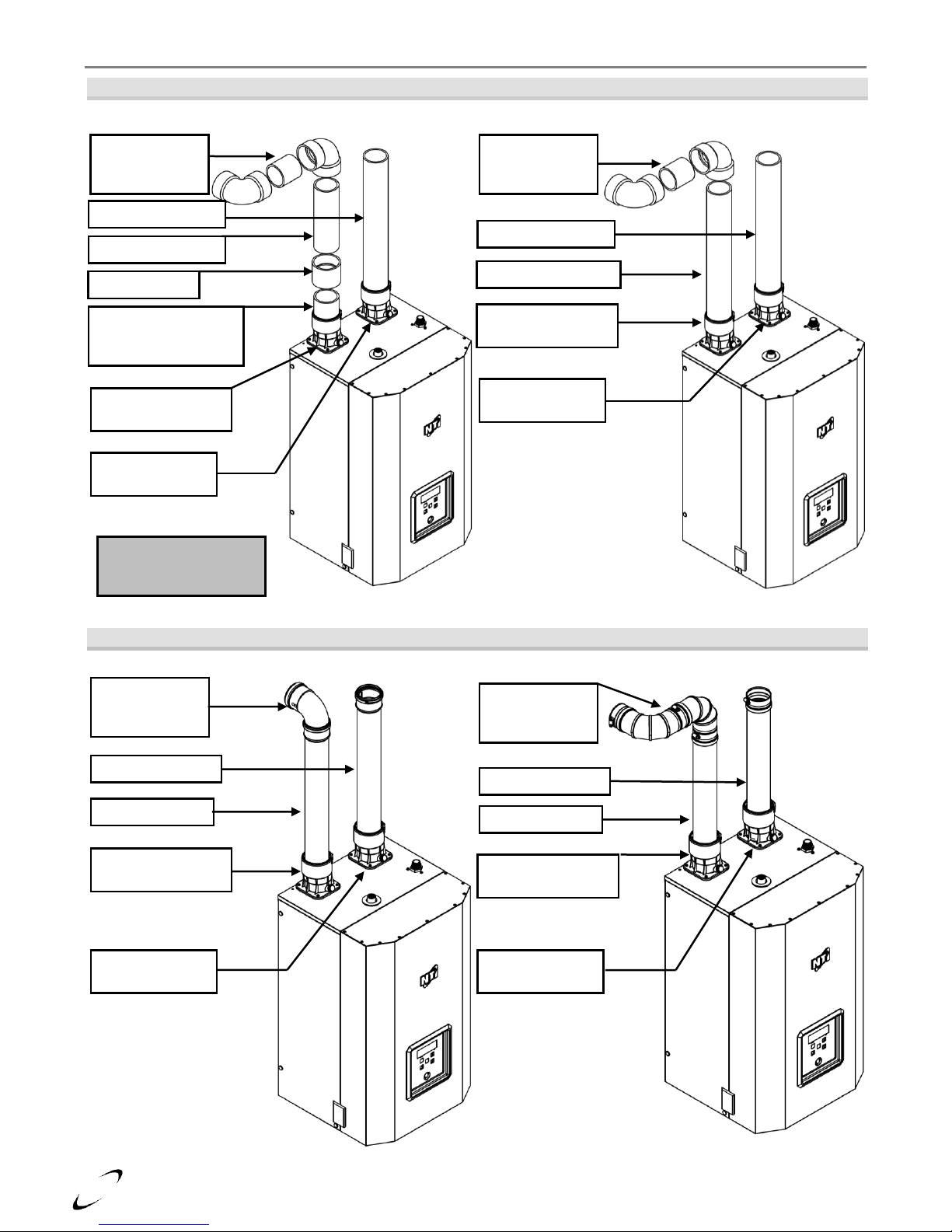
Figure 4-3(a) FTV150-190(C)
Figure 4-3(b) FTV150-190(C)
Near Boiler Venting (PVC)
Near Boiler Venting (CPVC)
Figure 4-3(c) FTV150-190(C)
Figure 4-3(d) FTV150-190(C)
Near Boiler Venting (PP)
Near Boiler Venting (SS)
Swing Joint
to attain slope in
horizontal runs
CPVC Transition Pipe
**minimum 5” long
(factory supplied)
Flue Outlet Adapter
(factory supplied)
**CPVC Transition Pipe
is mandatory when
venting with PVC
PVC Coupling
Air-inlet Adapter
(factory supplied)
PVC Air-inlet Pipe*
PVC Exhaust Vent
PP Elbow w.
offset angle to
account for slope
Flue Outlet Adapter
(factory supplied)
Air-inlet Adapter
(factory supplied)
PP Air-inlet Pipe*
PP Exhaust Vent
Swing Joint
to attain slope in
horizontal runs
Flue Outlet Adapter
(factory supplied)
Air-inlet Adapter
(factory supplied)
SS Air-inlet Pipe
SS Exhaust Vent
Swing Joint
to attain slope in
horizontal runs
Flue Outlet Adapter
(factory supplied)
Air-inlet Adapter
(factory supplied)
PVC Air-inlet Pipe*
CPVC Exhaust Vent
FTV I&O Manual │General Venting
Air-inlet - check with applicable local codes for acceptable pipe material.
Page 16
16
Items 1
Materials
2, 3
Venting System Standards
All Vent and Air-Inlet
materials installed on gas
fired appliances in CAN/US
must meet the specifications
provided in this Table.
Failure to comply could
result in fire, serious injury
or death.
United States
Canada 4
Vent Piping
and Fittings
PVC - DWV
ANSI/ASTM D2265
In Canada, all exhaust
vent material must be
ULC S636 approved.
PVC Schedule 40
ANSI/ASTM D1785
CPVC Schedule 40
ANSI/ASTM F441
Stainless Steel (SS)
UL-1738
Polypropylene (PP)
-
Pipe Cement
PVC
ANSI/ASTM D2564
CPVC
ANSI/ASTM F493
Primers
PVC / CPVC
ANSI/ASTM F656
Notes:
1
Refer to Table 4-5 for Allowable Vent and Air-inlet Pipe Sizes and Lengths.
2
PVC venting (exhaust and air-inlet) is not permitted within the Closet/alcove of a Closet/alcove installation.
3
The Air-inlet does not require high temperature pipe material; ABS and PVC Foam Core piping is acceptable. Check
applicable local codes for acceptable materials.
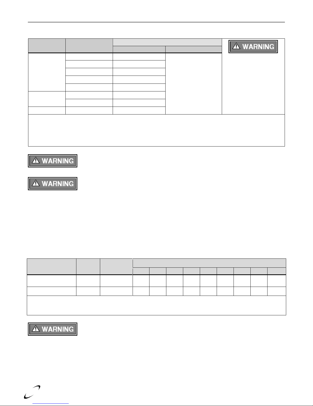
Models
Pipe Size
(in.)
Length (ft.) 2
Number of Elbows (90’s or 45’s) and Equivalent Feet
1 2 3 4 5 6 7 8 9
FTV110/110C &
FTV150/150C Only
2 1 100
95
90
85
80
75
70
65
60
55
All FTV Models
3
150
145
140
135
130
125
120
115
110
105
Notes:
1
See WARNING below.
2
Minimum length of each the exhaust vent and combustion air-inlet piping is 6 feet equivalent.
General Venting │ FTV I&O Manual
Vent/Air-inlet Pipe Material
Table 4-2 Approved Vent and Air-inlet Pipe Material
The use of cellular core PVC (ASTM F891), cellular core CPVC, or Radel®
(polyphenolsulfone) in the exhaust venting system is prohibited. Failure to follow these
Vent/Air-inlet Pipe Length Determination
Use Table 4-3 to determine the maximum pipe length that can be used. The table calculates 90º elbows, and 45º
elbows at 5 equivalent feet each.
Example: When using 3 in. pipe, the FTV can be installed with 150 equivalent feet of air-inlet piping and 150
equivalent feet of exhaust-vent piping. See Table 4-3 for more details.
Table 4-3 Allowable Vent and Air-inlet Pipe Size and Lengths
instructions may result in property damage, personal injury or death.
Covering non-metallic vent pipe and fittings with thermal insulation is prohibited. Failure
to follow these instructions may result in property damage, personal injury or death.
PVC Exhaust Venting – When using 2 inch PVC venting, the first seven (7) equivalent
feet of exhaust venting must be approved 2 inch CPVC or 3 inch PVC.
Page 17
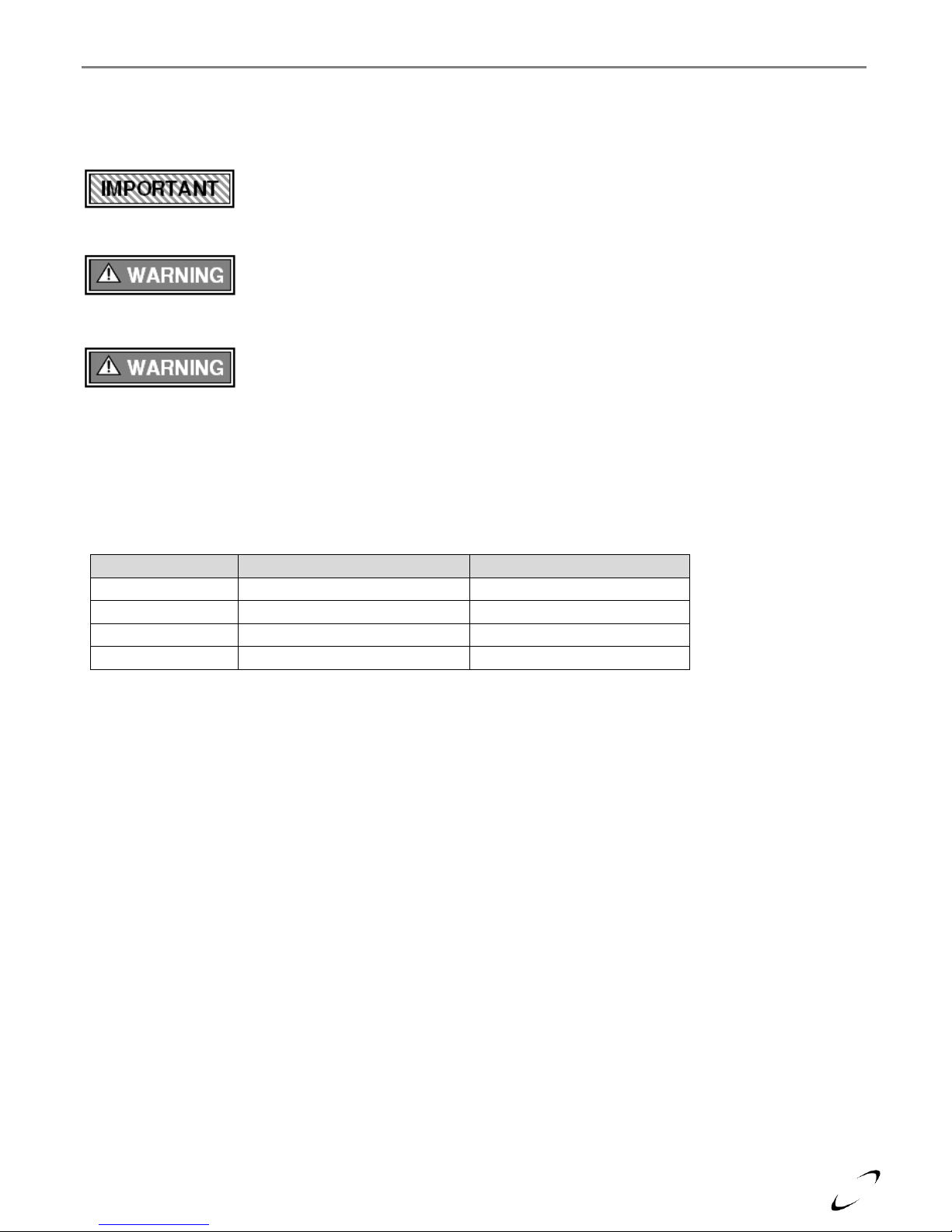
17
Venting Brand
Vent Manufacturer
Contact Information
System 636®
IPEX Inc.
www.ipexinc.com
PolyPro®
DuraVent
www.duravent.com
InnoFlue®
Centrotherm Eco Systems
www.centrotherm.us.com
Z-DENS®
Z-Flex Venting Systems
www.z-flex.com
FTV I&O Manual │General Venting
Termination Options – Direct Vent Installation
The venting system of the FTV boilers may be terminated using field supplied piping to construct a “Two-Pipe”
termination, see Figures 4-4(a), 4-5(a), 4-5(d), 4-6(a), 4-7(a) and 4-7(d); alternatively the venting may be
terminated using a factory kit selected from Table 4-5.
Optional Termination Kits – Direct Vent Installation
Kits certified with the FTV are listed in Table 4-5 and available from the manufacturers listed in Table 4-4. Kits
with an NTI part number listed in Table 4-5, are available directly from NTI.
Table 4-4 Optional Termination Kit OEMs
Sidewall Termination - Due to potential moisture loading (build-up) along the exterior
wall, sidewall venting may not be the preferred venting option. Refer to Figures 4-5 and
4-7 for roof top venting options.
The vent for this appliance shall not terminate over public walkways; or near soffit vents
or crawl space vents or other area where condensate of vapor could create a nuisance or
hazard or cause property damage; or where condensate or vapor could cause damage or
could be detrimental to the operation of regulators, relief valves, or other equipment.
Extra precaution must be taken to adequately support the weight of the Vent/Air-inlet
piping in applications using roof-top terminations. Failure to follow these instructions
may result in venting or boiler component failure resulting in flue gas spillage leading to
property damage, serious injury or death.
Page 18

18
Description
Vent
Size
Supplier p/n
Figure
Vent Material
Compatibility
Vent Option
Roof
Wall
IPEX Low Profile
(Wall)
7
2”
196984 (NTI p/n 85062)
4-4(b), 4-6(c)
PVC/CPVC
7
3”
196985 (NTI p/n 84357)
IPEX Concentric
(Wall/Roof)
4,5,6,7
2”
196125
4-4(c), 4-5(c),
4-6(b), 4-7(b)
3”
196116 (NTI p/n 84634)
197117
PolyPro® Concentric
(Wall)
2-3”
2PPS-HK, 3PPS-HK
4-4(c), 4-6(d)
PolyPro®
Polypropylene
PolyPro® Concentric
(Roof)
2-3”
2PPS-VK, 3PPS-VK
4-5(c), 4-7(c)
InnoFlue® Flush Mount
(Wall)
2-3”
ISLPT0202, ISLPT0303
4-4(b), 4-6(c)
InnoFlue®
Polypropylene
InnoFlue® Concentric
(Wall)
2-3”
4-4(c), 4-6(d)
InnoFlue® Concentric
(Roof)
2-3”
(ICRT2439 & ICTC0224),
(ICRT3539 & ICTC0335)
4-5(c), 4-7(c)
Z-DENS® Concentric
(Wall)
2-3”
2ZDHK2, 2ZDHK3
4-4(c), 4-6(d)
Z-DENS®
Polypropylene
Z-DENS® Concentric
(Roof)
2-3”
2ZDVK2, 2ZDVK3
4-5(c), 4-7(c)
Notes:
1
Instructions included with termination kits contain detailed assembly and installation instructions.
2
Clearance requirements in this manual supersede those of the instructions included with the vent terminal.
3
Piping MUST be secured to the vent terminal during installation.
4
IPEX Concentric Terminal MUST be cemented together and to the vent pipes during installation.
5
Vent Screens provided with boiler may be used with the IPEX Concentric Vent Kits; otherwise use IPEX vent screens (2
in. vent screen p/n 196050; 3 in. vent screen p/n 196051 – each sold separately).
6
IPEX Low Profile and Concentric kits (excluding p/n 197117) are constructed out of ULC S636 approved PVC; check
with your local authority for the acceptance of PVC as a venting material prior to use.
7
IPEX Concentric kits can be shortened to fit the requirements of the installation; see instructions included with the kit for
more details.
General Venting │ FTV I&O Manual
Table 4-5 Optional Vent Termination Kits
PVC In Canada - Authorities in some jurisdictions may not allow the use of any PVC
venting materials with condensing boilers; check with the local safety inspector to verify
compliance prior to installing a PVC Concentric Vent Kit with a FTV.
Page 19
19
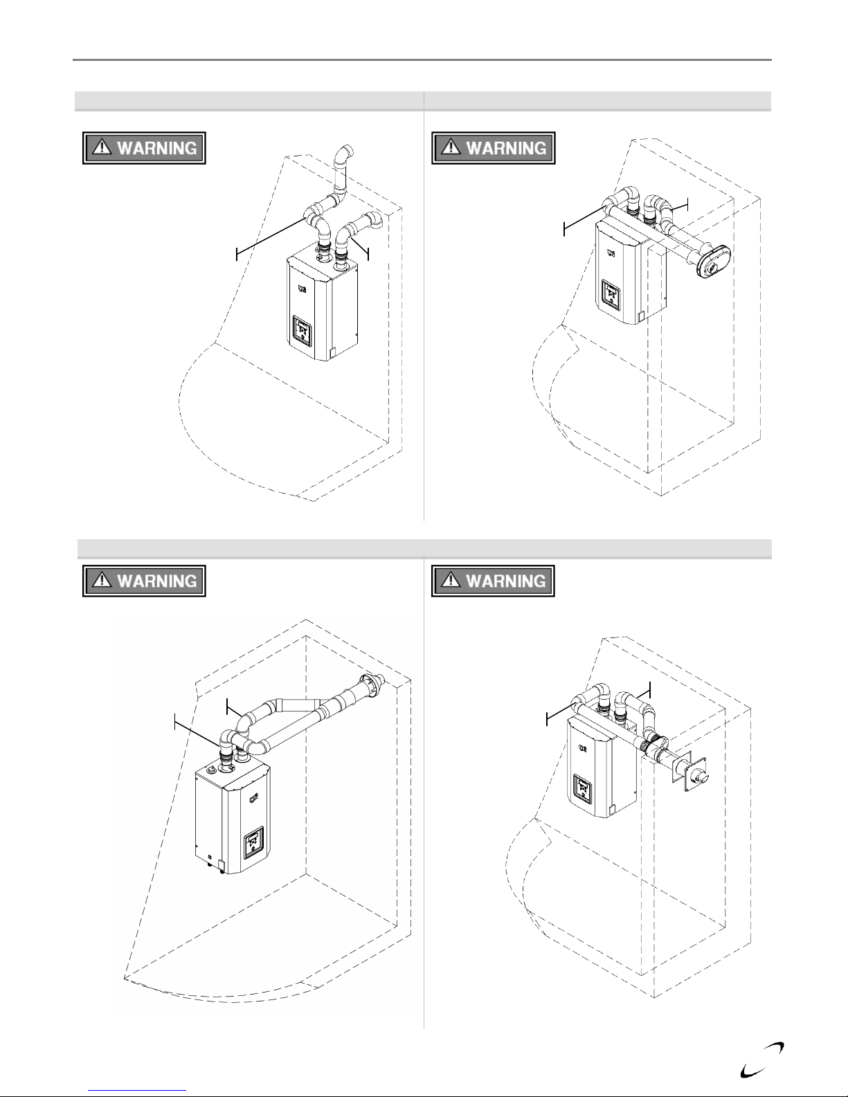
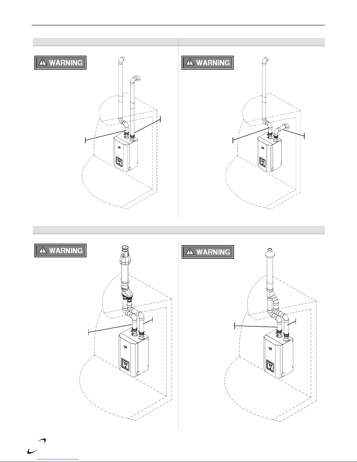
Figure 4-4 (a) Two-pipe Termination (Sidewall)
Figure 4-4 (b) Low Profile Termination (Sidewall)
Figure 4-4 (c) Concentric Termination (Sidewall)
Location of exhaust and air-inlet
connections vary between
models, see Figure 4-3.
Exhaust
Inlet
Location of exhaust and air-inlet
connections vary between
models, see Figure 4-3.
Exhaust
Inlet
Location of exhaust and air-inlet
connections vary between
models, see Figure 4-3.
Exhaust
Inlet
Location of exhaust and air-inlet
connections vary between
models, see Figure 4-3.
Exhaust
Inlet
FTV I&O Manual │General Venting
Page 20
20
Figure 4-5 (a) Two-pipe Termination (Roof)
Figure 4-5 (b) Two-pipe Termination (Roof/Sidewall)
Figure 4-5 (c) Concentric Termination (Roof)
Location of exhaust and air-inlet
connections vary between
models, see Figure 4-3.
Exhaust
Inlet
Exhaust
Inlet
Location of exhaust and air-inlet
connections vary between
models, see Figure 4-3.
Location of exhaust and air-inlet
connections vary between
models, see Figure 4-3.
Exhaust
Inlet
Exhaust
Inlet
Location of exhaust and air-inlet
connections vary between
models, see Figure 4-3.
General Venting │ FTV I&O Manual
Page 21
21
Sidewall Termination Details – Direct Vent Installation
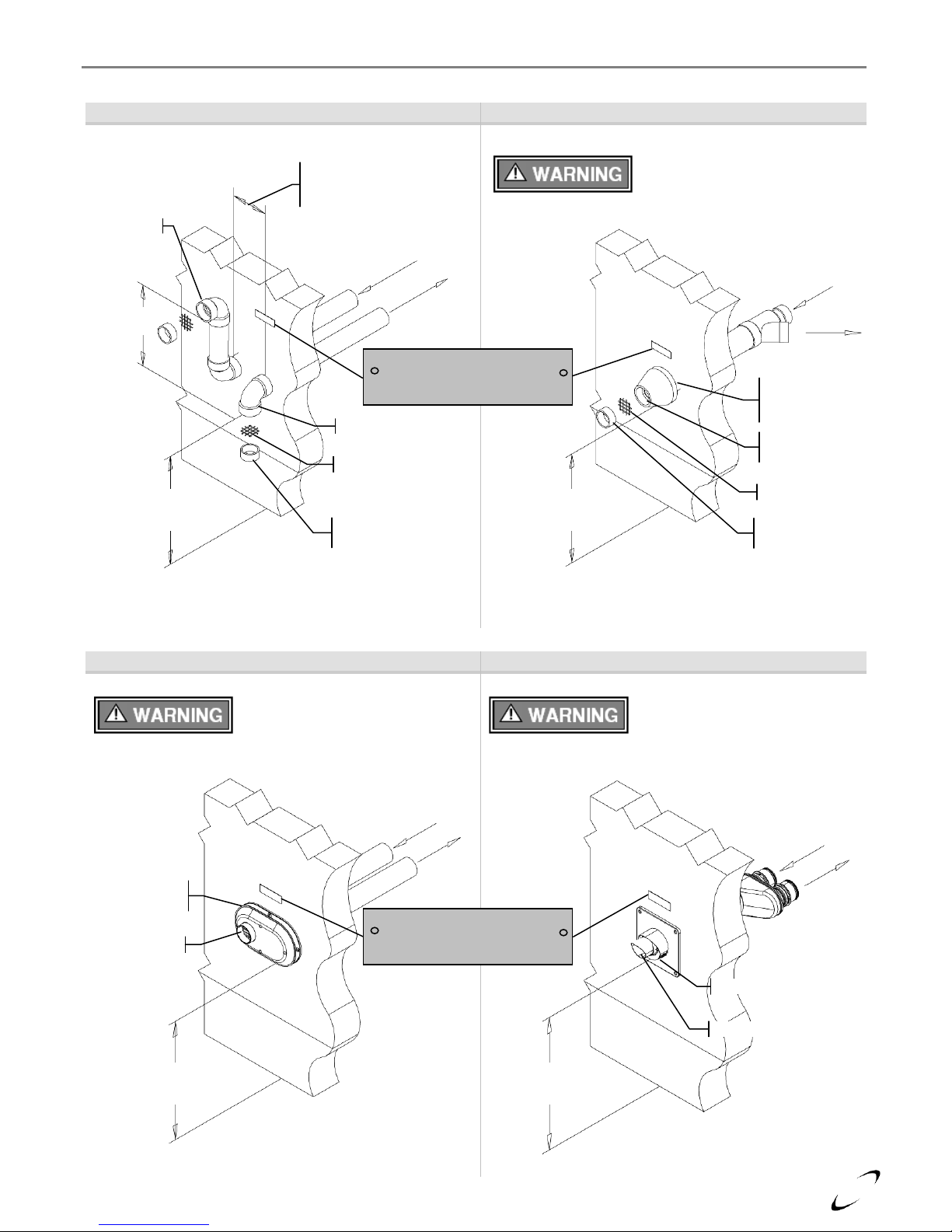
Figure 4-6 (a) Two-Pipe Termination (Sidewall)
Figure 4-6 (b) IPEX Concentric Termination
Refer to documentation included with termination kit for
complete installation instructions.
Figure 4-6 (c) Low Profile Termination (Sidewall)
Figure 4-6 (d) PolyPro / InnoFlue Termination
Refer to documentation included with termination kit for
complete installation instructions.
Min. 12”
above grade
or snow level
Exhaust
Air-inlet
Exhaust
Air-inlet around
perimeter
Min. 12”
above grade
or snow level
Exhaust center
Air-inlet bottom
Exhaust
Air-inlet
Gas Vent Directly Below
Keep Free of Obstructions
Refer to documentation included with termination kit for
complete installation instructions.
Exhaust
Air-inlet
Min. 12”
above grade
or snow level
Vertical
Min. 18”
Horizontal
4-12” or greater
than 36”
Exhaust
Air-inlet
Vent Screen
Vent pipe piece to
retain vent screen
Gas Vent Directly Below
Keep Free of Obstructions
Exhaust
Air-inlet
Min. 12”
above grade
or snow level
Air-inlet around
perimeter (1-2”
from wall)
Exhaust through
center
Vent Screen
Vent pipe piece to
retain vent screen
FTV I&O Manual │General Venting
Page 22
22
Roof Termination Details – Direct Vent Installation
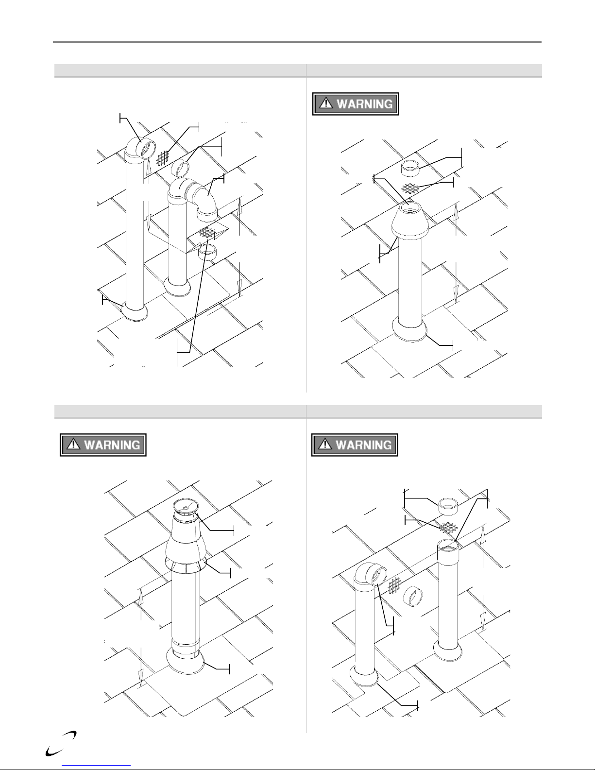
Figure 4-7 (a) Two-Pipe Termination (Roof)
Figure 4-7 (b) IPEX Concentric Termination (Roof)
Figure 4-7 (c) PolyPro / InnoFlue Termination (Roof)
Figure 4-7 (d) Exhaust only Termination (Roof)
Min. 12”
above grade
or snow level
Vent Screen
Vent pipe piece to
retain vent screen
Exhaust
Air-inlet
Vertical
Min. 18”
Horizontal
4-12” or greater
than 36”
Flashing
Min. 12”
above grade
or snow level
Vent Screen
Vent pipe piece to
retain vent screen
Exhaust center
Air-inlet around
perimeter
Flashing
Refer to documentation included with termination kit for
complete installation instructions.
Refer to documentation included with termination kit for
complete installation instructions.
Min. 12”
above grade
or snow level
Flashing
Exhaust
Air-inlet
Figure illustrates two options for exhaust termination only;
neither vent pipe illustrated is for combustion air-inlet.
Min. 12”
above grade
or snow level
Flashing
Vent pipe piece to
retain vent screen
Vent Screen
Exhaust
Option 1
Exhaust
Option 2
General Venting │ FTV I&O Manual
Page 23

23
FTV I&O Manual │General Venting
Venting Rules and Guidelines
1. Prevailing Winds: Ensure the vent is located where it will not be exposed to normal prevailing winds.
2. Combustion Air-inlet Contamination: Air for combustion must be drawn from an area free of dust and
contaminants. Combustion air containing chemicals such as chloride, fluoride, bromine or iodine or dust and
debris will cause corrosion damage of the heat exchanger voiding your NTI warranty. Refer to Table 4-1 for
a list of corrosive products and contaminants sources to avoid.
3. Vertical Separation: The exhaust must be a minimum of 18 in. above the air-inlet, and the air-inlet must
always be a minimum of 12 in. plus snow allowance above any surface that will support snow. (Two feet
plus snow allowance is highly recommended). Consult your weather office for the maximum typical
snowfall for your region.
Example: New Brunswick Canada - typical maximum snowfall is 19 in., thus the inlet must be (12”+19”) =
31 in. above grade and exhaust must be (31”+18”) = 49” above grade.
4. Horizontal Separation: The horizontal distance between the inlet and exhaust must be a minimum of 4”
[102 mm] center to center.
5. Wall Flashing: Under normal operating conditions this boiler will produce a plume of white gases, and
should be taken into consideration when selecting an adequate location. A 36 in. diameter stainless, plastic,
or vinyl shield can be used to flash the exterior of the residence.
6. Flue Gas Hazard: Position the vent termination where vapors cannot make accidental contact with people
and pets or damage nearby shrubs and plants.
7. Elbow Extensions: Elbows on outside of wall must be no more than ½ in. away from the wall.
8. Vent Sloping: All indoor exhaust piping must be on a slope back to the boiler a minimum of ¼ in. per
linear foot of vent. For applications where excessive condensation is possible ½ in. per linear foot is
recommended.
9. Vent Supports: Where required Vent and Air-inlet piping shall be secured to the wall for more rigidity. All
interior vent pipe shall be supported a minimum of every 36 in..
10. Roof Exhaust: In all roof applications the discharge must point away from the pitch of the roof.
11. Roof Flashing: Install adequate flashing where the pipe enters the roof, to prevent water leakage.
12. Rain Cap: Install and seal a rain cap over existing chimney openings, in vacant chimney applications.
13. Venting Below Grade: For installations that exit the wall below grade refer to Figure 4-8.
14. Vent Screens: Install factory supplied vent screens on the outside of the last elbow for both the inlet and
exhaust vent terminal elbows. Install the screen into the female opening of the elbow, and then cut a small
piece of pipe to sandwich the screen into the elbow. NOTE: ensure the small piece of pipe cut, does not
extend past the end of the elbow. Two screens are provided in the package. See Figures 4-6 and 4-7.
15. Condensate Hazard: Do not locate vent over public walkways, driveways or parking lots. Condensate
could drip and freeze resulting in a slip hazard or damage to vehicles and machinery.
16. Warning Plate: For Sidewall Venting, install the warning plate “Gas Vent Directly Below”, directly above
(within 4 ft. vertically) the location of the air-inlet pipe, so it is visible from at least 8 ft away. See Figure 4-
6.
17. Wall Thickness: Direct vent terminations are designed to work with any standard wall thickness.
Installation guidelines for min/max wall thickness are as follows: Min. = 1 in., Max. = 60 in..
18. Venting Options: Due to potential moisture loading (build-up) along the exterior wall, sidewall venting
may not be the preferred venting option. Refer to Figures 4-5 and 4-7 for roof top venting options.
Page 24

24
Figure 4-8 Venting Below Grade
For installations that exit the wall below grade:
1. Excavate site to a point below where the pipes
are to exit as shown.
2. Ensure the wall is fully sealed where the pipes
penetrate.
3. The Vent/Air-inlet piping MUST be secured to
the side of the building above grade, as shown,
to provide rigidity.
4. Ensure that the Vent/Air-inlet clearances are
maintained, see Section 5.0 for details.
Figure 4-9 Outdoor Venting
Vent piping outside the building is permitted under
the following conditions:
1. The maximum length outside the building is 20 ft.
Note that outdoor length must be included in the
overall vent length calculation.
2. All normal termination clearances are maintained.
3. The pipe is supported every 24 in..
4. The exhaust and inlet are sloped back to the boiler
½ in. elevation for every linear foot.
Figure 4-10 Existing Chimney Chase Way
It is permissible to use an existing chimney as a chase
way to run the Vent/Air-inlet piping as long as:
1. The chimney is not being used by any other
boiler.
2. Flue gases do not enter the vacant chimney.
3. Only FTV certified venting materials are used,
see Table 4-2.
4. Vent lengths are within the maximums specified.
5. The top of the chimney is capped and the
Vent/Air-inlet pipes are flashed to prevent
leakage into the vacant chimney.
Exhaust
Air-inlet
Wall Brackets
Supports every
24 in. [610 mm]
12 in. [305 mm] plus snow
allowance above grade
Air-Inlet
Maximum of 20 ft.
[6.1 m] is permitted
for piping outside a
building.
Exhaust
Vent
Gas Vent Directly Below
Keep Free of Obstructions
Air-Inlet
Existing
Chimney
(used as a
chase way)
Chimney
Cap
Exhaust Vent
Exhaust Vent Min.
18 in. above airinlet
Air-Inlet
Min. 12 in. above
roof and snow level
General Venting │ FTV I&O Manual
Under no circumstances may an existing chimney or chase-way be used to vent or
provide combustion intake air to a FTV. Failure to follow these instructions will result in
fire, property damage, serious injury or death.
Page 25
25
Clearances to Air-inlet Termination
Canada 1
USA 2
Min. Distance
Min. Distance
A
Above grade/roofline and snow level 8
12 in.
305 mm
12 in.
305 mm
B
Above roof line - Concentric Vent
6, 11, 13
24 in.
610 mm
24 in.
610 mm
C
To exhaust vent from any other boiler
36 in.
915 mm
12 in.
305 mm
Clearances to Exhaust Vent Termination
Min. Distance
Min. Distance
A
Above grade/roofline and snow level 8
12 in.
305 mm
12 in.
305 mm
D
Minimum vertical separation above air-inlet 9
18 in.
457 mm
18 in.
457 mm
E
Minimum horizontal separation from air-inlet 3
4 in.
102 mm
4 in.
102 mm
F
Window or door that may be opened, or other building opening
36 in.
915 mm
12 in.
305 mm
G
To combustion air-inlet of any other appliance
36 in.
915 mm
12 in.
305 mm
H
Non-mechanical air supply inlet to building
36 in.
915 mm
12 in.
305 mm
I
Mechanical air supply inlet to building 4
6 ft.
1.83 m
3 ft.
915 mm
J
Soffit, overhang, eave or parapet
24 in.
610 mm
24 in.
610 mm
K
Soffit vent or vent opening in an overhang, eave or parapet
6 ft.
1.83 m
6 ft.
1.83 m
L
Outside corner 10
- - -
-
M
Inside corner of an L-shaped structure (including walls and fences)
36 in.
915 mm
36 in.
915 mm
N
Service regulator / vent outlet
36 in.
915 mm
36 in.
915 mm
P
Each side of center line above or below meter / regulator assembly 5
36 in.
915 mm
36 in.
915 mm
Q
Above a paved sidewalk, driveway, or parking lot on public property if adjacent 12
7 ft.
2.13 m
7 ft.
2.13 m
R
Above a public walkway
X X X
X
S
Above a sidewalk or paved driveway that is located between two single family
dwellings and services both dwellings
X X X
X
T
Under a concrete veranda, porch, deck, or balcony 7
24 in.
610 mm
24 in.
610 mm
U
Above, under or near exterior stairs
X X X
X
V
Into a canopy or carport
X X X
X
Notes:
1 - Canadian installations must comply with the current CSA B149.1 Natural Gas and Propane Installation Code and local
building codes.
2 - US installations must comply with current ANSI Z223.1/ NFPA 54 National Fuel Gas Code and local building codes.
3 - Horizontal separation center-to-center (c.c.) 4”-12” (102-305 mm).
4 - For US installations, an exhaust vent must be 3 ft above a mechanical air supply inlet if within 10 ft. [3 m] horizontally.
5 - Horizontal clearance must be observed up to a height of 15 ft. [4.6 m] above/below the meter, regulator, or relief devices.
6 - Concentric Vent must protrude from the roof precisely 24” [610 mm] measuring from the terminal end-cap vanes.
7 - Permitted if veranda, porch, deck, or balcony is made of concrete and a minimum of two sides are fully open beneath.
8 - 24” is the recommended snow level allowance above grade/roofline or any surface that will support snow, debris, or ice
(i.e. for roof venting clearances - roofline and snow level). If living in a snowfall region, consult your local weather
office for the maximum typical snowfall for your area.
9 - Note that the vent must maintain a minimum vertical distance above the air-inlet. Example: Vent height = 18” (457
mm) above air-inlet + 12” (305 mm) for air-inlet above grade/roof line and snow level = 30” (762 mm) above grade
and snow level.
10 - Clearances to an outside corner to be in accordance with local installation codes.
11 - In Canada, concentric vent materials are subject to approval by local inspectors. See Termination Kits in Section 4.0.
12 - Above public walkways, driveways or parking lots if adjacent to it and condensate cannot drip, freeze, or create a hazard.
13 - Contact the manufacturer for special exemptions relating to multiple boiler installations using concentric vents.
FTV I&O Manual │Condensate Drain
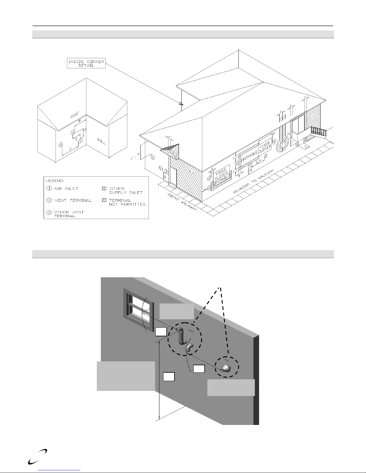
5.0 VENT/AIR-INLET TERMINATION CLEARANCES
instructions detailed in this section are a combination of FTV specific and National Gas Code restrictions.
Compliance alone does not insure a satisfactory installation as good common sense must also be applied. Failure
to follow these instructions may result in fire, property damage, serious injury or death.
Table 5-1 Termination Clearances Quick Reference Table (See Figures 5-1 and 5-2)
The quick reference table below is to be read in conjunction with the numbered notes as
indicated, Figures 5-1 and 5-2, and the Venting Rules and Guidelines in Section 4.0. The
Page 26
26
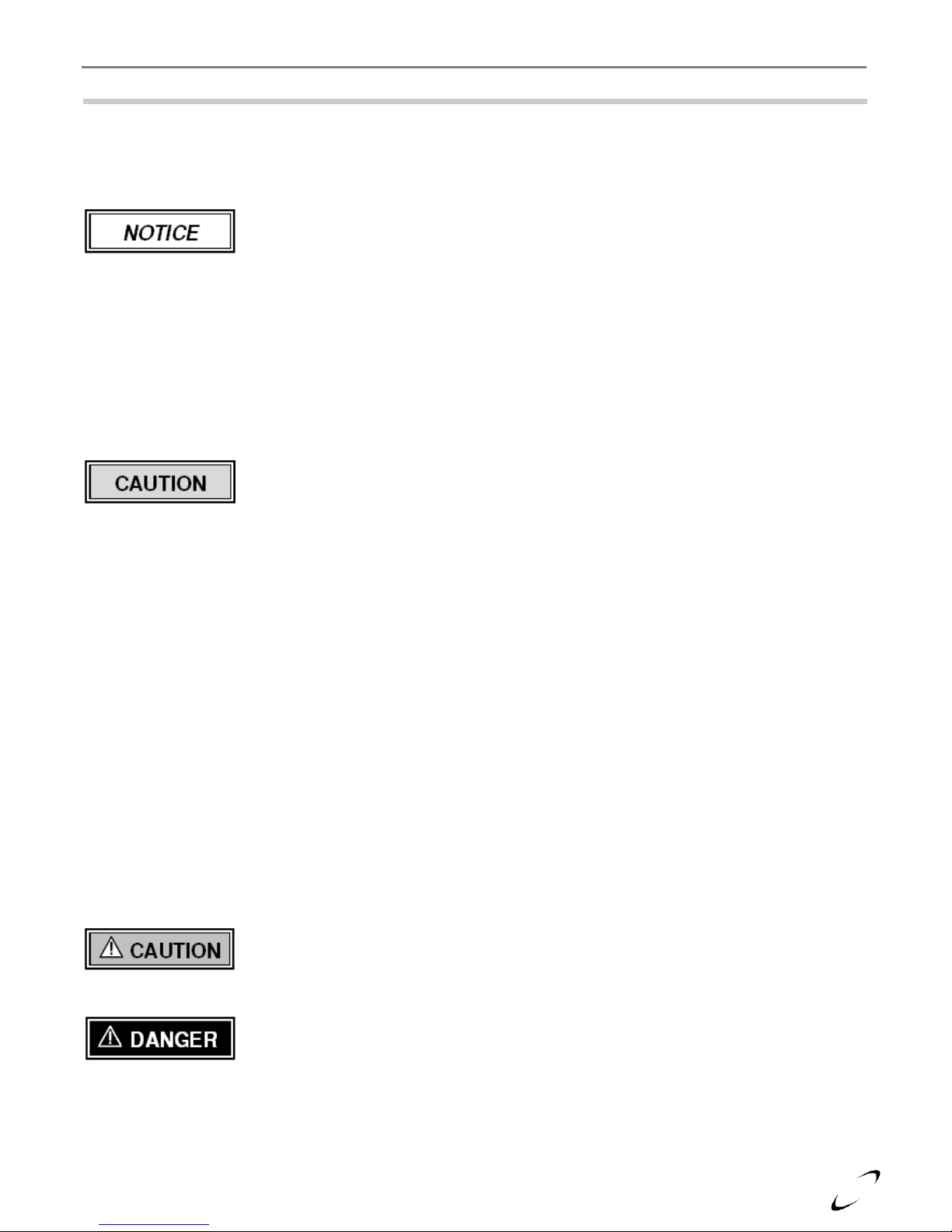
G – Letter represents a specific Termination Position. Refer to Table 5-1 for corresponding termination clearances.
Concentric Vent
Termination
Q
Two-Pipe
Termination
F
Clearance “Q”
Adjacent to Public
Walkway or Driveway
Minimum 7ft. [2.13 m]
G
Clearances “F” and “G”
Canada – Minimum 3 ft. [915 mm]
The US – Minimum 1 ft. [305 mm]
Condensate Drain│ FTV I&O Manual
Figure 5-1 Termination Clearance Quick Reference Diagram (See Table 5-1)
Illustrations of Termination Clearances
Figure 5-2 Sidewall Termination (See Table 5-1)
Page 27
27
FTV I&O Manual │Condensate Drain
6.0 CONDENSATE DRAIN
The FTV boilers produce liquid condensate in the heat exchanger and venting system as a product of
combustion. Steps must be taken to ensure condensate does not collect in the venting system; therefore, all
exhaust piping must slope back to the boiler a minimum ¼ in. per linear foot of vent. Condensate must be
drained from the unit into a household drain.
Check with your municipality, or local gas company to determine if the disposal of
combustion condensate is permitted in your area (e.g. in the State of Massachusetts the
The following are important notes that must be taken into consideration when constructing the condensate drain
system (see Condensate Trap Installation Instructions for further details):
DO NOT install condensate lines outside. A frozen or blocked drain will cause the condensate to back-up
and leak. This may result in damage to boiler components resulting in a no heat condition; property damage
may also occur.
NEVER use copper, steel, or galvanized piping in the construction of the condensate system (condensate is
very corrosive and will corrode most metals).
When a condensate pump is used or required, select a pump that is designed for residential furnaces.
Condensate Trap Installation Instructions (see Figure 6-1)
(Note: the Condensate Trap is factory supplied with the boiler and must be field installed)
1. Inspect Condensate Trap Assembly – Inspect the Condensate Trap to ensure all parts were shipped with
the assembly (see Figure 6-1). The Condensate Trap must be periodically disassembled and cleaned as part
of a regular maintenance plan.
2. Attach Corrugated Outlet Tube – Remove the Outlet Retaining Nut and Outlet Gasket and slide
components onto the Corrugated Outlet Tube – note orientation (gasket should be positioned
approximately 1/8” from the edge of the outlet tube – see Figure 6-1). Press the Corrugated Outlet Tube
into the Condensate Trap Outlet and firmly hand-tighten the Outlet Retaining Nut.
3. Attach to Boiler Condensate Drain (A) – Ensure the Ball-float is placed inside the condensate trap,
position the Inlet Gasket in between the condensate trap and boiler condensate outlet (See Figure 6-1).
4. Attach to Boiler Condensate Drain (B) – Secure the Condensate Trap into place by firmly hand-
tightening the Inlet Retaining Nut.
5. Outlet to Drain – Route the condensate from the Corrugated Outlet Tube to a household drain, condensate
pump or neutralizer (check with your local authority regarding the disposal of condensate), being careful
NOT to route it higher than the Condensate Trap outlet (see Figure 6-1).
condensate must be neutralized prior to entering a drain).
All tubing, drains and surfaces that come in contact with condensate draining from the
boiler, must be constructed out of corrosion resistant material; copper, steel and
galvanized are not acceptable materials for draining condensate. Failure to abide by this
caution will result in property damage.
The Condensate Trap must be periodically disassembled and cleaned as part of a regular
maintenance plan. Failure to clean the trap regularly can cause condensate drain blockage
leading to boiler malfunction, property damage and even personal injury.
Carefully follow the above instructions and the accompanying figure – check to ensure
the condensate trap is secure to the bottom of the boiler and that no strain is placed on it.
Failure to install the condensate trap properly will result in flue gas spillage and leeching
of carbon monoxide emissions into the surroundings resulting in serious injury or death.
Page 28

28
Boiler Condensate Drain
Outlet Gasket
Ball-float
Figure 6-1 Condensate Drain Piping
Inlet Gasket
Outlet
Corrugated Outlet Tube
Outlet Retaining Nut
Outlet Gasket
Inlet
Cleanout Cap
Condensate Trap
Inlet Retaining Nut
firmly tightened
Corrugated Outlet Tube routed to household
drain, condensate pump or neutralizer (no strain
applied on tubing or condensate drain assembly)
Condensate Drain│ FTV I&O Manual
Page 29

29
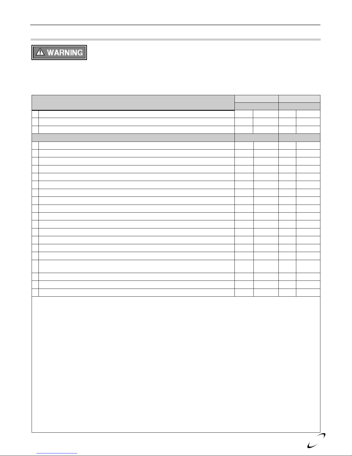
Model
Kit Number
LP-Venturi Insert (part no.)
FTV110 & FTV110C
85995-1
85989
FTV150 & FTV150C
85446-1
85536
FTV190 & FTV190C
85934-1
85812
Note:
FTV models are converted to Propane using a replacement LP-Venturi Insert, not
by installing an orifice. Follow the Natural Gas to LP Conversion Instructions
provided with the Kit.
FTV I&O Manual │Lighting the Boiler
7.0 INSTALLING GAS PIPING
FTV boilers are factory set to operate with Natural Gas; BEFORE OPERATING
WITH PROPANE, the boiler must be converted using the appropriate Natural to LP
Conversion Kit; see Table 7-1. Failure to properly convert the unit to safely operate with
Propane will cause dangerous burner operation, resulting in property damage, serious
Table 7-1 Natural Gas to LP Conversion Kit
injury or death.
Liquefied Petroleum (LP) propane gas is heavier than air. Do not install the boiler in a pit
or similar location that will permit heavier than air gas to collect. Check with Local
Codes as they may require boilers fueled with LP gas to be provided with an approved
means of removing unburned gases from the room. Failure to follow these instructions
may result in serious injury or death.
Installation
Refer to the current National Fuel Gas Code ANSI Z223.1/NFPA 54 or CAN/CGA B149.1 installation codes,
and local codes for gas piping requirements and sizing. Pipe size running to the unit depends on:
Length of pipe.
Number of fittings.
Type of gas.
Maximum input requirement of all gas boilers in the residence.
Ensure that:
The gas line connection to the boiler does not apply any weight to the gas valve. NTI recommends using
approved flexible gas piping (if acceptable by local codes) to connect the boiler to the gas supply (see Figure
7-1 for details).
You plan the installation so the piping does not interfere with the vent pipe, or the removal of the valve,
burner, and serviceable components.
The Boiler is installed such that the gas ignition system components are protected from water (dripping,
spraying, rain etc.) during installation and servicing.
The gas piping is large enough for all the gas appliances in the home. No appreciable drop in line pressure
should occur when any unit (or combination of units) lights or runs. Use common gas-line sizing practices.
Always use a pipe-threading compound that is resistant to Propane (LP) gas solvent action. Apply sparingly
to all male threads, starting at two threads from the end. Over doping or applying dope to the female end,
can result in a blocked gas line.
DO NOT TIGHTEN FITTINGS WITHOUT SUPPORTING THE INTERNAL GAS LINE CONNECTION
WITHIN THE BOILER as damage to the boiler’s internal gas carrying components could occur.
Install a manual “Equipment Shut-Off Valve” as shown in Figure 7-1. Valve must be listed by a nationally
recognized testing laboratory.
The gas line piping can safely be removed from the boiler for servicing, by strategically placing the gas line
shutoff and union; see example in Figure 7-1.
All gas piping, including gas components in the boiler, are checked for leaks using a “Bubble Test”, prior to
operating the boiler.
Strain on the gas valve and fittings may result in vibration, premature component failure
and leakage and may result in a fire, explosion, property damage, serious injury or death.
Do not use an open flame to test for gas leaks. Failure to follow these instructions may
result in fire, property damage, serious injury or death.
Page 30

30
Figure 7-1 Gas Line Connection (Typical)
Test all gas piping, internal and external to the boiler, for leaks. Failure to follow these
instructions may result in fire, property damage, serious injury or death.
Union
Drip Leg
Manual Gas Shutoff Valve
Should overheating occur or the gas
supply fails to shutoff, close the Manual
Gas Shutoff Valve to the boiler.
Flexible Gas Line Piping
Recommended to eliminate strain
on the boiler gas components (only
use if acceptable by local codes).
Rigid Gas Line Piping
Use only rigid gas line piping within the
boiler cabinet. Rigid piping must protrude
beyond the outside of the cabinet wall.
Lighting the Boiler│ FTV I&O Manual
When performing a pressure test on the gas line piping, be sure the boiler is disconnected
or isolated if the test pressure is expected to exceed 1/2 PSI (14 in. w.c.), as damage to the
gas valve could occur resulting in fire, property damage, serious injury or death.
Page 31

FTV I&O Manual │Lighting the Boiler
31
8.0 LIGHTING THE BOILER
Before Start-up refer to Mandatory Pre-commissioning Procedure for Plastic Venting
in Section 4.0. Failure to follow these instructions can result in explosions, injury or death.
Prior to turning the gas supply on and lighting the boiler, ensure all aspects of the
installation are complete and in conformance with the instructions provided in this
manual, including the Vent/Air-inlet, Condensate Drain, and System Water Piping.
Failure to precisely follow these instructions will cause a fire or explosion resulting in
property damage, serious injury or death.
Do not store or use gasoline or other flammable vapors & liquids in the vicinity of this or
any other boiler. Failure to follow instructions could result in explosion causing property
damage, serious injury or death.
If you do not follow these instructions exactly, a fire or explosion may result causing
property damage, serious injury or death.
Should overheating occur or the gas supply fails to shutoff, close the Manual Gas Shutoff
Valve to the boiler. Failure to follow instructions could result in explosion causing
property damage, serious injury or death.
FOR YOUR SAFETY, READ BEFORE OPERATING_
A) This boiler does not have a pilot. It is equipped with an ignition device which automatically lights the
burner. Do not try to light the burner by hand.
B) BEFORE OPERATING smell all around the boiler area for gas. Be sure to smell next to the floor
because some gas is heavier than air and will settle on the floor.
WHAT TO DO IF YOU SMELL GAS:
• Do not try to light any boiler.
• Do not touch any electric switch.
• Do not use any phone in your building.
• Immediately call your gas supplier from a neighbor's phone. Follow the gas supplier's instructions.
• If you cannot reach your gas supplier, call the fire department.
C) Use only your hand to turn the gas “shutoff” valve. Never use tools. If the handle will not turn by hand, do
not try to repair it, call a qualified service technician. Force or attempted repair may result in a fire or
explosion.
D) Do not use this boiler if any part has been under water. Immediately call a qualified service technician
to inspect the boiler and to replace any part of the control system and any gas control which has been
under water.
1. STOP! Read the safety information above very carefully.
2. Set the thermostat to lowest setting. Turn off all electric power to the boiler.
3. This boiler does not have a pilot. It is equipped with an ignition device which automatically lights the
burner. Do not try to light the burner by hand.
4. Turn the manual gas valve to the OFF position. Remove front access panel.
5. Wait five (5) minutes to clear out any gas. Then smell for gas, including near the floor. If you smell gas,
STOP! Follow “B” in the safety information above. If you do not smell gas, go to the next step.
6. Turn the manual gas valve ON. Wait an additional five (5) minutes smelling for gas.
7. Replace the front access panel.
8. Set thermostat to highest setting. Turn on all electric power to the boiler.
9. Ignition sequence is automatic. Combustion will occur after a brief fan purge.
10. If ignition does not occur, follow the instructions “To Turn Off Gas To Boiler” and call your service
technician or gas supplier.
1. STOP! Read the safety information above very carefully.
2. Turn off all electric power to the boiler
3. Turn the manual gas valve to the OFF position
OPERATING INSTRUCTIONS_
TO TURN OFF GAS TO THE BOILER_
Page 32

32
Lighting the Boiler│ FTV I&O Manual
Ensure the boiler is wired in accordance with this manual.
Ensure the gas shutoff valve is turned on, and that the gas system has been fully tested for leaks.
Ensure the system is completely filled with water, and that ALL the air is purged out.
Ensure the Vent and Air-inlet piping is completely installed in accordance with this manual.
Initial Start-Up
Each time the power is turned on to the boiler, the control will go through a “de-air” sequence designed to purge
air from the boiler. The de-air sequence takes 14 minutes to execute, during which time the circulators will be
operating in a cyclical manner and the burner will not attempt to function. Once the de-air sequence has been
executed at least once, subsequent de-air sequences can be bypassed by holding the “OK” button until “de-Air” is
no longer displayed on the screen; see Section 17.0 for more details.
1. Turn on power to the boiler and turn-up the Thermostat(s). The boiler should run through a purge, and
combustion should occur. (The control system has a built-in ignition retry, allowing the system to try at least
five times, before locking-out).
2. With the unit operating at full capacity, verify that the gas line pressure is 4-10.5 inches w.c. for Natural gas,
and 9-13 inches w.c. for Propane (see Section 9.0 for details).
3. Using an appropriate Oxygen (O2) or Carbon Dioxide (CO2) analyzer, take a sample of the flue gas. The
sample must fall within the acceptable ranges for CO2 (see Section 9.0 for details).
4. Perform at least three ignitions in succession to ensure proper operation.
5. After the three successive ignitions, unplug the flame sensor and allow the unit to cycle again. The flame
safety system will allow the unit to go through 5 ignition cycles before going to “Loc 1”. Once you have
confirmed this behavior, reinstall the wire on the flame sensor, press the reset button and reconfirm proper
ignition.
Re-lighting Unit
1. Stop and read these instructions very carefully.
2. Set the thermostat to the lowest setting, and then turn off all power to the boiler.
3. This boiler does not have a pilot. It is equipped with an ignition device that automatically lights the burner.
Do not try to light the burner by hand.
4. Turn the gas shutoff valve to the off position, and then remove the front cover.
5. Wait five (5) minutes to clear out any gas. Then check for gas, including near the floor. If you smell gas
“Stop” and follow “B” above (see FOR YOUR SAFETY, READ BEFORE OPERATING). If you do
not detect any gas proceed to the next step.
6. Turn the gas shutoff valve to the on position, wait an addition five (5) minutes and check for gas.
7. Replace the front cover.
8. Set the thermostat to the highest setting, and then turn on all power to the boiler.
9. Ignition sequence is automatic, combustion will occur after a brief fan purge. Ignition will retry 3 times.
10. If ignition does not occur, “Turn off the gas and electricity to the boiler” and contact a qualified service
technician, or gas supplier.
The initial lighting of the boiler must be performed by a licensed Gas Technician.
Failure to follow instructions may result in property damage, serious injury or death.
Allow primers/cements to cure for 8 hours prior to Start-up. If curing time is less than 8
hours, first perform Steps 2 through 6 of Mandatory Pre-commissioning Procedure for
Plastic Venting in Section 4.0. Failure to follow these instructions can result in explosion,
serious injury or death.
The flame probe is located in the burner plate; it has a single white/semi-transparent wire
connected to it. DO NOT remove the orange spark cable from the ignition electrode (also
located in the burner plate); this device is used for spark ignition and produces 20,000
Volts potential which would result in an EXTREME ELECTRICAL SHOCK possibly
causing serious injury or death.
If the unit fails to light consistently and smoothly, contact NTI for technical assistance at
1-800-688-2575. Never allow the boiler to operate if the ignition or operation of the
burner is rough or erratic. Failure to follow these instructions may result in serious injury
or death.
Page 33

33
FTV I&O Manual │Lighting the Boiler
Turning Off the Boiler
1. Set the thermostat to the lowest setting, and then turn off all power to the boiler.
2. Turn the gas shutoff valve to the off position.
Page 34

34
Gas
Line Pressure (inches w.c.)
CO2 (%)
CO (ppm)
Max.
Nominal/Desired
Min.
Max.
Min.
Max.
Natural
7
4
10.5 9 10
175
Propane
11
8
13
10
11
175
Notes:
1
Combustion calibration must only be performed with the burner operating at maximum modulation rate.
2
Combustion values listed are for burner operation at maximum modulation rate; CO2 and CO values will be lower at minimum
modulation rate.
3
When tested at minimum modulation rate, the CO2 must be 0.5-1.0% lower than CO2 at maximum modulation rate.
Model
Gas
Appliance
Number
Min. Modulation Rate
(RPM)
Max. Modulation Rate
(RPM)
Input Rate (MBH)
Min
Max *
FTV110
NG
16
1620
7620
11
110
LP
22
1860
8040
FTV110C
NG
19
1620
7620
LP
23
1860
8040
FTV150
NG/LP
17
1740
8220
15
150
FTV150C
NG/LP
20
FTV190
NG/LP
18
1620
8280
19
190
FTV190C
NG/LP
21
* Canada: Altitudes between 2000-4500 ft, de-rate by 10%. Consult local authorities for de-rating for altitudes above 4500ft.
Gas Valve and Burner Set-up │ FTV I&O Manual
9.0 GAS VALVE AND BURNER SET-UP
Set-up of the FTV gas valve must be performed by a licensed Gas Technician. Failure to
perform the set-up correctly may result in incorrect operation, component failure,
Gas Line Pressure
The boiler gas valve is equipped with a line pressure test port; see Figure 9-1. Use the following procedure to
measure the gas line pressure to the boiler to ensure if falls within the range given in Table 9-1:
1. Turn the supply of gas to the boiler off.
2. Open the bleed screw of the line pressure test port approximately 1-1/2 turns. This port is directly connected
to the gas line feeding the boiler. See Figure 9-1.
3. Force ¼ in. ID tubing over the housing of the line pressure test port; install the other end of the tubing to an
appropriate line pressure test gauge or manometer. Ensure both ends of the tubing make a tight connection.
4. Open the supply of gas to the boiler and check for gas leaks.
5. Observe the line pressure under static conditions and compare it to Table 9-1. The pressure will be greatest
under static conditions.
6. With all other gas appliances in the application running, operate the burner to the maximum firing rate (see
Table 9-2) and compare the observed line pressure with Table 9-1. The pressure will be lowest during the
maximum flow of gas.
7. Adjust the gas line pressure to ensure the parameters in Table 9-1 are attained under all conditions (see
NOTICE below). If possible adjust the line pressure to the "Nominal/Desired" value listed in Table 9-1,
while the unit is operating at the maximum modulation rate, see Table 9-2.
8. Continue observing the gas line pressure until the completion of the combustion analyses, in case
adjustments need to be made.
9. Complete pressure testing, and then return the bleed screw of the Line Pressure Test Port to the closed
position.
Table 9-1 Line Pressure and Combustion Parameters
property damage, serious injury or death.
The line pressure is a function of the gas supply and is affected solely by field provided
parameters such as line size and regulator settings. Under no circumstances can the boiler
gas valve influence or be used to adjust the gas line pressure.
Failure to close the bleed screw of the Line Pressure Test Port will cause a severe leakage
of gas, resulting in a fire or explosion causing property damage, serious injury or death.
Table 9-2 Minimum and Maximum Modulation Rates
Page 35

35
Throttle/Input Adjustment Screw
Increase gas
Turn Counter Clockwise
Decrease gas
Turn Clockwise
FTV I&O Manual │Gas Valve and Burner Set-up
Carbon Monoxide - Never leave the unit operating while producing Carbon Monoxide
(CO) concentrations in excess of 175ppm. Failure to follow this warning may result in
Adjustment
Throttle / Input Screw Adjustments - The boiler is equipped with a Throttle/Input Adjustment Screw, located
on the Gas Valve. It is used to adjust the flow of gas leaving the gas valve entering the Venturi and then the
combustion air stream. Turn the Throttle screw in (clockwise) to reduce the flow of gas, make combustion
leaner, and reduce the concentration of CO2 in the flue gases. Turn the Throttle screw out (counterclockwise)
to increase the CO2 level and flow of gas in the combustion air stream. Typical adjustment required is 0-1/2
of a turn in or out from the factory setting. See Figure 9-1 for Throttle screw location and Table 9-1 for
appropriate CO2 levels.
Combustion Calibration - To calibrate burner operation, perform the following procedure using a calibrated
combustion analyzer capable of measuring CO2 and CO from Natural and Propane Gas burning boilers:
1. Operate the unit at the maximum modulation rate, see Table 9-2. NOTICE: the modulation rates must
be adjusted for models FTV110 & FTV110C operating with Propane; this is accomplished by adjusting
the Appliance Number to the value provided in Table 9-2 – see section titled “Controller Replacement
Instructions” on page 74 of these Instructions.
2. Ensure the gas line pressure is maintained within tolerance, see Table 9-1.
3. While at the maximum modulation rate, measure the CO2 and CO; adjust as necessary, using the Throttle
Screw, to be within the limits listed in Table 9-1.
4. Operate the unit at the minimum modulation rate (see Table 9-2). Ensure the combustion remains
smooth and CO2 and CO values are lower than the values obtained during maximum modulation, per
notes in Table 9-1. If not, do not adjust further, contact NTI for assistance.
Flue Gas Analysis and Adjustment
Each FTV is factory set to operate with Natural Gas, for boilers field converted to operate with Propane Gas, a
flue gas analysis and adjustment is mandatory. See Table 7-1 for the correct Natural Gas to LP Conversion Kit.
Analysis – Perform flue gas analysis, and adjust throttle/input screw as required until CO2 and CO levels are
within acceptable limits.
serious injury or death.
Manifold Pressure - DO NOT adjust or measure the Manifold Pressure of the boiler.
Correct manifold pressure is factory set. Field adjustment could result in improper burner
operation resulting in fire, explosion, property damage or death.
Adjustments to the Throttle/Input Screw may only be made by a qualified gas technician,
while using a calibrated combustion analyzer capable of measuring CO2 and CO.
Adjustments may only be performed if the gas line pressure is maintained above
minimum levels throughout the duration of the test, see Table 9-1. Failure to follow these
instructions may result in serious injury or death.
Failure to perform the flue gas analysis and adjustment detailed in this section may result
in erratic and unreliable burner operation, leading to reduced efficiency, increased fuel
consumption, reduced component life, heat exchanger combustion deposits, and general
unsafe operation. Failure to follow these instructions may result in serious injury or
death.
Page 36

36
Figure 9-1 Gas Valve and Venturi Assembly (FTV150 Illustrated)
DO NOT Adjust
Gas Valve
Manifold Pressure
Test Port
Throttle / Input
Adjustment Screw
Line Pressure
Test Port
Venturi
Gas Valve and Burner Set-up │ FTV I&O Manual
Page 37

FTV I&O Manual │Boiler and Heating System Piping
37
10.0 BOILER AND HEATING SYSTEM PIPING
The fire tube design of the FTV heat exchanger results in minimal head loss, however it must be considered
when sizing system piping and circulators. Furthermore, the low mass of the FTV heat exchanger requires a
minimum flow rate anytime the burner is operating. To maintain the efficient and reliable operation of the heat
exchanger, and to avoid heat exchanger failure, it is critical to ensure the rules and guidelines in this section are
followed.
Failure to follow the instructions provided in this section will void the NTI warranty and
may result in property damage, fire, serious injury or death.
Water Quality
Water Quality is important to the proper operation and lifespan of the boiler; the information on water quality
provided in this document must be followed. Damage caused by failure to follow these requirements will not be
covered by the warranty.
During installation and yearly maintenance, the water quality must be checked. Common water quality heat
exchanger failures, are easily prevented when properly addressed.
Follow these system water best practices:
- Test system fill water and understand what you are putting into the system.
- Ensure that there is adequate air elimination in the system.
- Treat all boiler feed water as though it is hard water.
- Use chemical inhibitors on every job
(note: some glycols contain inhibitors – do not mix dissimilar inhibitors).
- Flush old and new systems with fresh clean water before commissioning a new boiler.
- Use magnetic dirt separators on systems containing large amounts of iron.
- Use Dirt Separators to remove debris from system water.
- Where possible, treat boiler feed water.
- Repair system leaks immediately to prevent oxygen (air) and untreated water from entering the system.
Proper equipment must be used to test the water. Digital meters are highly recommended because they can be
calibrated. The use of test strips is not recommended because they degrade over time and can be influenced by
many factors.
System Cleaning – Existing and new heating systems must be cleaned with a hydronic system cleaner; see list
of recommended hydronic system cleaners below; equivalent products from other manufacturers may also be
used. System cleaner must be drained and thoroughly flushed with clean water to remove any residual
cleaner, prior to installing a new boiler. NEVER leave a system cleaner for longer than recommended by the
manufacturer of the cleaner; follow the instructions provided by the system cleaner manufacturer.
• Noble Noburst Hydronic System Cleaner
• Fernox F3 Cleaner (NTI part no. 83449)
• Rhomar Hydro-Solv 9100
• Sentinel X400
Air Elimination – A micro bubble air elimination device must be installed on every boiler installation.
Automatic air-vents alone are not an acceptable substitute for a micro bubble air elimination device. Below
are a few examples of acceptable devices.
• Spirovent
• Taco 4900 series
• Caleffi Discal
Automatic feed valves should not be left open indefinitely. In the event of a leak, an automatic feed valve
will continue to supply fresh untreated water into the heating system. Fresh water contains both oxygen and
added minerals, one or both of these could lead to scaling and/or corrosion of the heat exchanger.
Page 38

38
Table 10-1 Boiler System Cleansers and Corrosion Inhibitors
Parameter
Range
Information
pH
7 to 9
The total pH scale ranges from 1 to 14, with 7 considered to
be neutral. A pH less than 7 is said to be acidic and solutions
with a pH greater than 7 are basic or alkaline.
Conductivity
100 to 300 μS/cm
Conductivity is an indirect method of determining the total
dissolved solids in the water. High conductivity in untreated
water indicates hard water. Adding corrosion inhibitors will
increase conductivity.
Hardness
50 to 200 ppm
(3 to 11.7 gpg)
Artificially soft water can damage the system. The use of unsoftened water is recommended. Do not use distilled or
purified water.
Chlorine
150 ppm
High Chlorine content in the water can damage the boilers
heat exchanger.
Glycol (if applicable)
20-50%
Concentrations below 20% can promote bacteria growth, and
concentrations above 50% will dramatically reduce
efficiency and may require de-rating the boiler. Inhibited
glycol mixed at 50% should have a pH 8-9. Check with
glycol manufacturer.
Total Dissolved Solids (TDS)
50 to 300 ppm
TDS includes calcium and magnesium associated with lime scale
but also includes other harmful solids such as magnetite, chlorides,
sodium and other organic and inorganic materials.
Bacteria/Mold
none
Glycol above 20% will kill any bacteria.
Molybdate Corrosion Inhibitor
100 to 300 ppm
Film-forming inhibitor that protects against iron corrosion.
Boiler and Heating System Piping │ FTV I&O Manual
Dirt Removal – A dirt removal device should be installed in all systems. In older systems containing cast iron
radiators/baseboard or large amount black iron or steel pipe, a magnetic dirt separator must be installed.
Glycol, Snow Melt, and Oxygen Permeable Piping – When freeze protection is required, only multi metal
inhibited propylene glycol, at a minimum of 20% and a maximum of 50%, is allowed for use with boiler
system. If the boiler is being used with a snow melt system that requires a concentration of glycol higher
than 50%, then a plate heat exchanger is required to separate the snow melt system from the boiler water.
Note: the use of glycol may reduce the usable output capacity of the boiler, thus requiring the unit to be
“down-fired” by limiting the maximum operating capacity and/or the maximum water temperature. If
oxygen permeable piping (non-oxygen barrier tubing) is used in the system a plate heat exchanger is required
to separate it from the boiler water.
Water Treatment – When filling the boiler system, the water must be tested. Table 10-1 outlines the
parameters that should be tested for, and the corresponding ranges that are permitted. Water quality that does
not fall within the stated ranges will void the warranty of the boiler. Utilize proper testing equipment, such as
digital meters, to verify water quality.
Inhibitors should be used for all installations in both new and existing heating systems. Follow the
instructions provided by the inhibitor manufacturer when adding to the system to ensure the correct
concentration. A list of approved inhibitors is provided below.
• Rhomar Pro-tek 922
• Sentinel X100
• Fernox Protector F1 (NTI part no. 83448)
Ethylene glycol is prohibited for use with the boiler, only inhibited propylene glycol is
allowed for use with the boiler.
Never use petroleum based compounds in the system for cleaning or sealing.
Page 39

39
Figure 10-1 Installation of Optional LWCO
Auto Air Vent – locate above the
LWCO to remove air during
commissioning (close vent-cap
afterwords to prevent water damage)
Low Water Cutoff Location
(when required by local authorities)
Install the LWCO in a suitable tee (reference
installation instructions provided with the LWCO)
as illustrated. DO NOT install isolation valves
between the boiler and the LWCO. The LWCO
switch must be wired to break the boiler limit
circuit or line power to the boiler (see Section
12.0 – Field Wiring).
NTI offers the following LWCO kit p/n 85253.
When the installation is complete, TEST THE
LWCO to ensure the burner shuts down when the
water level drops.
FTV I&O Manual │Boiler and Heating System Piping
Near Boiler Plumbing (Central Heating)
FTV boilers are intended solely for use in pressurized closed-loop heating systems operating with a minimum
pressure of 12 PSI at the boiler outlet. Carefully follow the instructions and piping diagrams illustrated in this
section.
Pressure Relief Valve – A Pressure Relief Valve is factory supplied with each unit, and must be field installed
in the vertical position, with the outlet facing horizontally and piped towards the floor away from where it
could be harmful; see Figure 10-2(a). NOTICE: FTV boilers have a maximum allowable operating pressure
of 50 PSI.
Pressure & Temperature Gauge – FTV boilers come with a factory supplied Pressure and Temperature
Gauge. The gauge must be installed at the boiler outlet prior to any circulators. See Figures 10-2(b), 10-2(c),
and 10-2(d).
Auto Air Vent – Install the factory supplied auto air vent directly above the outlet fitting on the top of the unit as
illustrated in Figure 10-2(a). Open the auto air vent’s vent-cap to promote the removal of air during
commissioning of the boiler and to avoid malfunctioning of the LWCO. Once the air is removed from the
system, close the vent-cap to prevent water from leaking onto the boiler.
Low Water Cutoff (LWCO) – FTV boilers are provided with a factory installed Water Pressure Sensor. The
sensor provides a reading of the boiler inlet water pressure on the display; in the event the pressure drops
below 7 PSI, the control will go to a blocking error “FILL”, inhibiting burner operation. Where required by
the Authority having jurisdiction, an external LWCO may have to be installed; see Figure 10-1.
FTV boilers are not approved for operation in an “open system,” thus it cannot be used
for direct potable water heating or process heating of any kind.
If installed in the incorrect orientation (horizontally with drain pipe out the bottom) the
relief valve may not function properly resulting in property damage or personal injury.
Ensure the discharge of the pressure relief is piped to a location where the steam or water
will not cause property damage or serious injury.
Page 40

40
Figure 10-2(a) Top (All Models)
Figure 10-2(b) Bottom (non-Combi)
Figure 10-2(c) Bottom (Combi – Option A)
Figure 10-2(d) Bottom (Combi – Option B)
Boiler Outlet
Pressure &
Temperature Gauge
(factory supplied)
Tee Fitting - Typical
(field supplied)
Boiler Inlet
30 PSI Relief Valve
(factory supplied)
Auto Air Vent
(factory supplied)
¾ in. Brass Street Elbow
(factory supplied)
¾ x ½ x ¾ in. Brass Tee
(factory supplied)
Pressure &
Temperature Gauge
(factory supplied)
Tee Fitting - Typical
(field supplied)
Boiler Outlet
Boiler Inlet
Gaskets – p/n 82368
(needed w. LL Header)
Pressure &
Temperature Gauge
(factory supplied)
Low Loss Header –
p/n 85110 (optional)
Heating Supply
Heating Return
Boiler and Heating System Piping │ FTV I&O Manual
Page 41

FTV I&O Manual │Boiler and Heating System Piping
41
Model
Flow
(US gpm)
The flow rate through the FTV-Combi is determined by
the available head of the internal pump (see Figure 10-4).
When piped “Direct to Zones” the boiler flow rate will be influenced by the
piping losses of the distribution system; to avoid no/low occurances, set the
manual bypass valve to “MAX” (see Figure 10-3).
When piped Primary/Secondary the FTV-Combi boiler flow rate will be fixed
at approximately 8 GPM for space heating demands.
FTV110
4.4
FTV150
6
FTV190
8
Boiler System Plumbing
FTV boilers use a low mass heat exchanger that requires a minimum rate of forced water circulation any time the
burner is operating (See Table 10-2 for minimum flow rate requirements). To ensure the minimum flow rate is
attained, NTI strongly recommends installing the boiler in a “Primary/Secondary” plumbing configuration
utilizing “Closely Spaced Tees” or a “Low Loss Header” to de-couple the Boiler-Primary loop from the SystemSecondary loop(s). See the examples of Primary/Secondary Loop configurations in Figures 10-6 through 10-9.
Table 10-2 Minimum Flow Rate Requirements
Failure to ensure the minimum water flow rate through the boiler when the burner is
operating will result in “short-cycling”, reduced performance and operating efficiency,
and may also cause overheating and premature failure which will void the warranty.
Failure to follow instructions may result in fire, property damage, serious injury or death.
Circulating Pump Outputs – FTV boilers are equipped with three 120VAC pump outputs:
1. DHW PUMP – operates during a Domestic Hot Water (DHW) demand. The DHW PUMP output is not
used on Combi models.
2. CH PUMP – operates during a Central Heat (CH) demand.
3. BOILER PUMP – operates during any demand. The internal pump for Combi models is factory wired to
the BOILER PUMP output.
Use of these circulator outputs will depend on the system configuration selected; see Figures 10-6 through 10-9.
For further pump output details and wiring instructions see Section 12.0.
Circulators responsible for forcing water flow through the boiler must be sized to
account for the head loss of the boiler and boiler piping at the required flow rate; see
Table 10-3 and Figure 10-5.
Internal Circulating Pump (FTV-Combi Only) – the FTV-Combi encorporates the ciculating pump
responsible for forcing water flow through the boiler, an can be utilized in one of two configurations:
1. Primary/Secondary – the internal circulator drives flow through the boiler only; see Figures 10-8 and 10-9.
2. Direct to Zones – the internal circulator drives flow through the boiler and the distribution system; see
Figure 10-10. This configuration is limited to zone valve (or non-zone circulator) distribution systems
with small flow requirements, i.e., systems requiring no more than 6 GPM at 9 ft. of head pressure. Plot
the expected head-loss of the distribution system against the “FTV-Combi Available Pump Head” curve
(Figure 10-4) to verify sufficient performance; NOTICE: if the available head from the internal pump
cannot support the needs of the distribution system, then a Primary/Secondary configuration must be
utilized.
Pressure Bypass Valve – to avoid no/low water flow occurances in applications of the
FTV-Combi in “Direct to Zone” configurations must fully utilize the FTV-Combi’s
internal pressure bypass valve. The internal pressure bypass valve is utilized by
adjusting the manual bypass valve to “MAX”; see Figure 10-3.
Page 42

42
Figure 10-3 Activating Pressure Bypass Valve (FTV-Combi Only)
Figure 10-4 Available Pump Head (FTV-Combi Internal Pump)
Notes:
1
Graph depicts available pump head of FTV-Combi internal pump, after boiler internal flow losses.
Manual Bypass Valve – set to MAX (fully clockwise) to
activate the Pressure Bypass Valve – mandatory when
piping is “Direct to Zones”.
Boiler and Heating System Piping │ FTV I&O Manual
Page 43

43
Model
Temp.
Rise (ºF)
Boiler Flow
Rate (GPM)
Boiler Head
Loss (ft.)
Minimum
Pipe Size
The flow rate through the
FTV-Combi is determined by
the available head of the internal pump (see Figure
10-4). When piped “Direct to Zones” the boiler
flow rate will be influenced by the piping losses of
the distribution system; to avoid no/low occurances,
set the manual bypass valve to “MAX” (see Figure
10-3).
When piped Primary/Secondary the FTV-Combi
boiler flow rate will be fixed at approximately 8
GPM for space heating demands.
FTV
110
20
10.5
5.5
1 in.
25
8.4
3.7
35 7 2.5
FTV
150
20
14.3
10.1
1.25 in.
25
11.4
6.5
1 in.
35
9.5
4.7
FTV
190
20
18.0
16
1.25 in.
25
14.4
10.2
35
10.3
5.4
1 in.
Figure 10-5 FTV110-190 Head Loss Curve
FTV I&O Manual │Boiler and Heating System Piping
Table 10-3 Boiler Pipe Size Requirements
Expansion Tank – The expansion tank must be sized in accordance with the water volume of the system as well
as the firing rate of the appliance. It is important to locate the expansion tank, and make-up water fill, on the
inlet side of any circulator in the system, as doing so will guarantee the lowest pressure in the system will be
at least equal to the tank and make-up water pressure. See examples in Figures 10-6 through 10-10.
Ensure the expansion tank cannot become isolated from the boiler anytime the system is
operating. The installation of flow checks, motorized valves or other shutoff devices
(other than for the purpose of servicing) are not permitted between the outlet of the boiler
Indirect Fired Water Heater – When installed as per Figure 10-7, the indirect fired water heater is in series
with the boiler during a demand for DHW. Therefore, its head loss, along with the head loss of the boiler and
associated piping, must be considered when sizing the circulator.
and the expansion tank; see Figures 10-6 through 10-10. Failure to follow these
instructions may result in discharge of the Pressure Relief Valve resulting in property
damage or personal injury.
Page 44

44
Figure 10-6 Plumbing Schematic – Single Central Heating Circulator (non-Combi)
Figure 10-6 illustrates the basic plumbing requirements for a non-Combi FTV boiler
installation with a single Central Heating circulator, and an Indirect Water Heater.
Boiler and Heating System Piping │ FTV I&O Manual
Figures 10-6 through 10-10 illustrate typical piping systems. These piping schematics do
not illustrate all of the required concepts and components required to have a proper
installation. Concepts not shown include: prevention of thermal-siphoning (heat traps),
isolation valves, drain and purge valves, etc. It is the responsibility of the installing contractor and system
designer to determine which system best meets the need of the installation and to consider all aspects of a proper
system design. Contractor modifications to these instructions may be required, based upon existing piping and
system design; consult NTI for required assistance (1-800-688-2575).
Page 45

45
Figure 10-7 Plumbing Schematic – Multiple Central Heating Circulators (non-Combi)
Figure 10-7 illustrates the basic plumbing requirements for a non-Combi FTV boiler
installation with multiple Central Heating circulators, and an Indirect Water Heater.
FTV I&O Manual │Boiler and Heating System Piping
Page 46

46
Figure 10-8 Plumbing Schematic – Multiple Central Heating Circulators (Combi)
Figure 10-8 illustrates the basic plumbing requirements for an FTV-Combi boiler
installation with multiple Central Heating circulators.
Low Loss Header
(p/n 85110)
Boiler and Heating System Piping │ FTV I&O Manual
Page 47

47
Figure 10-9 Plumbing Schematic – Single Central Heating Circulator – Primary/Secondary (Combi)
Figure 10-9 illustrates the basic plumbing requirements for an FTV-Combi boiler
installation with a single Central Heating circulator in Primary/Secondary configuration.
Low Loss Header
(p/n 85110)
FTV I&O Manual │Boiler and Heating System Piping
Page 48

48
Figure 10-10 Plumbing Schematic – Direct to Zones (Combi)
Figure 10-10 illustrates the basic plumbing requirements for an FTV-Combi boiler
installation piped “Direct to Zones”. Limited to zone valve (or non-zone circulator)
distribution systems with small flow requirements, i.e., systems requiring no more than 6
GPM at 9 ft. of head pressure.
Manual Bypass Valve –
set to MAX (fully clockwise).
Boiler and Heating System Piping │ FTV I&O Manual
Page 49

49
FTV I&O Manual │Boiler and Heating System Piping
11.0 DOMESTIC HOT WATER (DHW) PIPING – COMBI ONLY
DHW Description of Operation
FTV Combi models incorporate a DHW heat exchanger (Brazed Plate) and the controls necessary to heat DHW
without requiring a separate water heater. When the internal flow sensor detects potable water flow in excess of
0.3gpm the controller operates in DHW mode, whereby the potable water is heated to the “DHW Setpoint”
(Installer Menu setting 2-07). Set “DHW Setpoint” to the desired hot water temperature; to avoid the risk of
scalding a Thermostatic Mixing Valve MUST be installed, see Figure 11-1.
Thermostatic Mixing Valve – due to the potentially high hot water temperatures exiting
the water heater, a thermostatic mixing valve (or equivalent anti-scald device) must be
installed according to Figure 11-1, local code and the installation instructions provided
with the the thermostatic mixing valve, to reduce scald hazard potential. Failure to
follow these instructions may result in serious injury or death.
Scald Hazard - Hotter water increases the risk of scald injury. There is a hot water scald
potential if a thermostatic mixing valve is not used or is set too high. Be sure to follow
the adjustment instructions provided with the thermostatic mixing valve. Failure to
follow these instructions may result in serious injury or death.
A scald injury can occur when hot steam or liquid makes contact with one or more layers
of skin. Scald severity (degree of burn) is directly impacted by exposure time and
temperature. Refer to Table 11-1. The following basic precautions are common sense:
Young children and elderly adults burn more quickly and should use cooler water.
Never leave a child alone while drawing water in a bathtub.
Test the water temperature before bathing or showering.
Turn cold water on first and then add hot water until the temperature is comfortable.
DHW Preheat Mode
For improved domestic hot water comfort, the FTV-Combi incorporates a “Preheat Mode” feature (Installer Menu
setting 2-10). When set to ON the boiler control will function to keep the DHW preheated to limit the wait time
associated with a tankless hot water system.
Preheat Operation – Once per hour, the controller will operate the boiler in DHW mode, firing the burner at
minimum power until the boiler Return achieves a temperature within 25°F of the DHW setpoint. Note: if the
DHW or boiler Return temperature is within 34°F of the DHW Setpoint, Preheat mode will not initiate.
Page 50

50
Figure 11-1 Near Boiler DHW Piping (Combi models)
Cold Water Supply
DHW to Fixtures
DHW Outlet (Hot)
DHW Inlet (Cold)
Drain Valve
Tempering Valve
(Manditory)
Y-Strainer
(factory supplied)
Isolation Valve
Boiler and Heating System Piping │ FTV I&O Manual
DHW Plumbing (FTV-Combi)
DHW Inlet & Outlet Connections – The FTV-Combi has two potable water connections, Inlet & Outlet, which
exit the bottom of the unit, nearest the back. The Inlet fitting is on the right and the Outlet fitting is on the
left, see Figure 11-1.
DHW Filter – Install the factory supplied Y-strainer prior to the inlet fitting, as illustrated in Figure 11-1. The
serviceable Y-strainer has a 100 micron filter and will protect the internals from damage caused by dirt and
debris.
Check Valve – The installation of a check valve in the hot water line is recommend to prevent expansion devises
downstream from back flowing when the water pressure drops during cold water draws. Failure to prevent
the backflow will cause a momentary forward flow of water through the flow sensor when the cold-water
draw has ended and the water pressure increases. This forward flow of water will momentarily activate DHW
mode.
Throttling Valve – Use one of the isolation valves, installed hot water line, as a throttle valve to regulate the
maximum hot water flow rate. The FTV-Combi has a limited firing rate (e.g.: only 110 MBH for model
FTV110C); therefore excessive flow rates will result in cooler hot water temperatures.
Drain and Isolation Valves – Install drain and isolation valves on the cold water inlet and hot water outlet lines,
as shown in Figure 11-1, to allow for servicing of the internal brazed plate heat exchanger and other potable
water components. It will be necessary to flush or clean the brazed plate heat exchanger, if it is exposed to
hard water.
Page 51

51
Figure 12-1 Wiring Terminal Access
Wire Protection – When passing wiring through the cabinet of the boiler, the
installer must use wire grommets suitable for securing the wiring and preventing
chafing. Failure to follow instructions may result in component failure, serious injury
or death.
Field Wiring Terminals
Control Panel Cover
Spare Fuse
Controller Fuse – 3.15A
5x20mm Slo-Blo®
Blower Fuse – 3AG
7A 250 Fast-acting
FTV I&O Manual │Boiler and Heating System Piping
12.0 FIELD WIRING
All wiring must be in accordance with the Canadian Electrical code CSA C22.1 and/or the National Electrical
Code ANSI/NFPA 70, local codes, and this manual. NOTICE: the boiler must be electrically grounded. The
electrical rating of the FTV is 120V / 1 Phase / 60 Hz / 12A.
Power Supply - FTV are designed to be powered using a single phase 120VAC power
supply that is fused (or protected via a circuit breaker) to allow a maximum of 15 Amps.
Wiring Connections
All field wiring connections to the boiler are made at barrier strips located on FTV control panel. The
connections are accessed by removing the front door of the boiler, followed by the removal of the control panel
cover; see Figure 12-1. Field wiring enters the cabinet through holes located on the bottom of the boiler cabinet,
then must be routed through holes in the bottom of the control panel; protect the wires from stain and chaffing
by using suitable strain-relief grommets when passing the wiring through the holes. Field wiring connections
are to be installed in accordance with instructions provided in Figure 12-2 and Table 12-1.
Controller Fuse (120VAC) – the FTV controller is equipped with a 3.15 Amp fuse that protects most 120VAC
circuits within the boiler, as well as any circulators connected to it. A spare fuse is located to the left of the
operating fuse in an open holder; see Figure 12-1.
Blower Fuse (120VAC) – an inline 7 Amp fuse, located in a fuse holder to the left of the ON/OFF power switch
(behind the support bracket), protects the 120VAC circuit of the combustion blower; see Figure 12-1.
Failure to follow instructions may result in component failure, serious injury or death.
Avoid Shocks – To Avoid Electrical Shock, turn off electrical power to the boiler prior
to opening any electrical box within the unit. Ensure the power remains off while any
wiring connections are being made. Failure to follow these instructions may result in
component failure, serious injury or death.
Page 52

52
Figure 12-2 Field Wiring
Remove jumper
when installing
an Aux. Limit
Boiler and Heating System Piping │ FTV I&O Manual
Labeling - Label all wires prior to disconnecting them when servicing controls. Wiring
errors can cause improper and dangerous operation. Failure to follow instructions may
result in property damage or personal injury.
Continuity - Before connecting the line voltage wiring, perform a continuity check
between all wires and ground to make sure that there are no electrical leaks that could
blow a fuse or damage electrical components. Also check the polarity of the line and
neutral wires. Line must measure 120VAC to ground; neutral must measure zero. Failure
to follow instructions may damage the unit.
Page 53

53
Connection
Location
Description
ARGUS LINK –
1
Argus Link Communication – used to cascade up to 16 boilers. Also for connection to
BMS Expansion Interface Module (for remote burner control – 0-10V).
ARGUS LINK +
2
SENSOR
COMMON
3
Sensor Common – Common port for field inputs SYSTEM, OUTDOOR and DHW.
SYSTEM
4
System Temperature Sensor (Manditory for Cascade) – Wire to terminals 3 and 4 of
the Manager boiler in a cascade. Sensor would be installed on the system supply pipe
feeding the Central Heating system to allow accurate control of system temperature.
Sensor is available from NTI, p/n: 84010.
OUTDOOR
5
Outdoor Temperature Sensor – A wall mountable OD Sensor is included with each
boiler; connect to terminals 3 and 5. In a cascade, the OD Sensor only needs to be
connected to the main boiler. The use of the OD Sensor is required to allow the boiler
control to automatically infer the heat load of a central heating system.
DHW
6
Tank Thermostat / Sensor (Not Applicable for FTV-Combi models) – Connect the
contacts of a DHW Tank Thermostat, or leads of an approved DHW Tank Sensor (NTI
p/n: 84632), to terminals 3 and 6. When using a Thermostat, set DHW mode = 2 (menu
setting 2-08). When using a Sensor, set DHW mode = 1. See Section 17.0 for more details.
THERMOSTAT
7
Room Thermostat Input – Connect central heat demand switch (room thermostats or
zone control end switch), or “nighttime setback” / “time of day” switch to terminals 7 and
8. Switch must be an isolated end switch.
8
Connection
Location
Description
EXT. LIM
9
120V Safety Limit Circuit (Factory jumpered) – wire the output contacts of any optional
external limit device (i.e. LWCO) in series with terminals 9 and 10. Note: if using an
external limit device, the factory jumper must be removed.
10
DHW PUMP
11
120VAC output to the DHW circulator; powered during a demand for DHW. Total load
of DHW PUMP and BOILER PUMP must not exceed 2.6Amps. Not applicable for FTVCombi models.
CH PUMP
12
120VAC output to the Central Heating circulator; powered during a demand for Central
Heat. Total load of CH PUMP and BOILER PUMP must not exceed 2.6Amps.
BOILER PUMP
13
120VAC output to the main boiler circulator; powered during all demands. Total load of
BOILER PUMP and CH PUMP (or DHW PUMP) must not exceed 2.6Amps. Not
applicable to FTV-Combi models – pump is factory wired.
L2 NEUTRAL
14
Location for connecting neutral of the power supply and all circulators.
15
L1 120VAC
16
Location for connecting line voltage of the power supply. Note; most installation codes
require the installation of a service switch to break line voltage to the appliance.
Ground
Green
Wire
Location for connecting earth ground and for grounding all circulators.
FTV I&O Manual │Boiler and Heating System Piping
ECM Pumps – due to the large inrush current of ECM pumps, they should only be
switched via an isolation relay, not directly via the boiler controller. Powering ECM
pumps directly will lead to premature failure of the boiler controller’s pump relay
contacts.
Max Load – The total load rating of circulators powered by outputs BOILER PUMP and
CH PUMP, or BOILER PUMP and DHW PUMP cannot exceed 2.6 Amps.
Page 54

54
Boiler and Heating System Piping │ FTV I&O Manual
13.0 CASCADE INSTRUCTIONS
The FTV controller has the internal capacity to cascade (lead-lag / stage) up to 16 FTV boilers, without the use of
an external controller. Use the instructions detailed in this section to set-up and install the cascade system.
FTV-Combi – cascades heating an Indirect Water Heater (IWH) cannot utilizes an FTV-
Combi as the Manager.
Figure 13-1 Cascade Plumbing Schematic
Page 55

FTV I&O Manual │Boiler and Heating System Piping
55
Communication Wiring – for each boiler in the cascade, wire in parallel electrical connections Argus Link (-)
and Argus Link (+), terminals 1 and 2 (see Figure 12-2).
Establish Managing Boiler – choose one boiler to be the Managing Boiler, this boiler will receive all control
wiring and will be used for setting control parameters (see steps below). All non-Managing Boilers
(Dependents) must have the “S4” switch (located on the top right side of the control) switched OFF. *
*Note: the “S4” switch is factory set to ON. The switch is in the off position when it is closest to the “S4”
marking. The “S4” switch must remain in the ON position on the Managing Boiler.
Plumbing – install the boilers in parallel in a primary/secondary plumbing configuration as illustrated in Figure
13-1.
System Sensor – install a system sensor (NTI p/n: 84010) on the outlet (supply) pipe feeding the heating system,
see Figure 13-1. Wire the system sensor to terminals 3 and 4 of the Managing Boiler (left boiler in
illustration).
IMPORTANT: the use of the system sensor is mandatory for proper operation of the boiler cascade system.
Outdoor Sensor – when using an outdoor sensor it must be connected to terminals 3 and 5 of the Managing
boiler (left boiler in illustration); outdoor sensors connected to non-Managing boilers will be ignored.
Boiler Pump – each boiler in the cascade must have its own circulator (see Figure 13-1) which is operated by
each respective boiler, via the BOILER PUMP output (terminal 13). For the FTV-Combi, the Boiler Pump is
located within the boiler, so an external circulator is only necessary if the factory supplied LL Header is
employed; in this case the external circulator is operated via the CH PUMP output (terminal 12).
CH Pump (System) – the Managing Boiler can control the System’s Central Heating Pump via its CH PUMP
output (terminal 12). IMPORTANT: due to the limited switching capacity of the CH PUMP output, it may be
necessary to use an isolation relay to activate the CH Pump, see Table 12-1.
DHW Pump (System) – the Managing Boiler can control the System’s DHW Pump via its DHW PUMP output
(terminal 11). IMPORTANT: due to the limited switching capacity of the DHW PUMP output, it may be
necessary to use an isolation relay to activate the DHW Pump, see Table 12-1.
Central Heat Demand Switch (Room Thermostat) – connect to terminals 7 and 8 (THERMOSTAT) of the
Managing Boiler. Switch must be an isolated end switch (dry contact). Central Heat settings are programed
from the Managing Boiler only, i.e. Installer menu settings 2-01, 2-02, 2-03, 2-04, 2-05 and 2-06.
Tank Thermostat / Sensor – connect to terminals 3 and 6 of the Managing Boiler. DHW settings are programed
from the Managing Boiler only, i.e. Installer menu settings 2-07, 2-08 and 2-09. Set DHW Mode (Installer
menu setting 2-08) according to device used; Thermostat = 2, Sensor = 1.
Boiler Address – assign a unique boiler address for each boiler in the cascade via Installer menu setting 2-20.
Managing boiler must be set = 1; other boilers must be set from 2 to 16.
Rotation Interval – establishes the time, in days, between advancements of the staging sequence of boilers in the
cascade; set via Installer menu setting 2-22 of the Managing Boiler.
Emergency Setpoint – establishes an emergency (back-up) boiler operating setpoint in the event communication
is lost between boilers, or if the system sensor is not connected. Set via Installer menu setting 2-21 of each
boiler in the cascade.
Page 56

56
# of Units
FTV110
FTV150
FTV190
Pipe Size
2
1-1/4”
1-1/2”
2”
3
1-1/2”
2”
2”
4
2”
2”
2-1/2”
5
2”
2-1/2”
2-1/2”
6
2-1/2”
2-1/2”
3”
7
2-1/2”
3”
3”
8
2-1/2”
3”
3”
9
2-1/2”
3”
3”
10
3”
3”
4”
11
3”
3”
4”
12
3”
4”
4”
13
3”
4”
4”
14
3”
4”
4”
15
3”
4”
4”
16
3”
4”
4”
Note: Minimum pipe size based on assumed temperature rise of 25ºF at
maximum firing rate.
Boiler and Heating System Piping │ FTV I&O Manual
Table 13-1 Minimum Pipe Sizes for Multiple Boiler Applications
Page 57

57
Figure 14-1 FTV Connection Diagram
FTV I&O Manual │Wiring Schematics
14.0 WIRING SCHEMATICS
Page 58

58
Figure 14-2 FTV Ladder-Logic Diagram
Wiring Schematics │ FTV I&O Manual
Page 59

59
FTV I&O Manual │Installation Checklist
15.0 INSTALLATION CHECKLIST
Installation
1. If operating on Propane Gas, convert boiler using appropriate Conversion Kit. See Table 7-1.
2. Locate the boiler in accordance with Section 3.0 of this manual.
3. Install the Vent/Air-inlet piping in accordance with Sections 4.0 and 5.0 of this manual. Ensure all joints
are secured and cemented properly. Perform the Mandatory Pre-commissioning Procedure for Plastic
Venting in Section 4.0.
4. Connect the condensate trap and drain in accordance with Section 6.0 of this manual.
5. Connect the gas supply in accordance with Section 7.0 of this manual.
6. Install the plumbing in accordance with this manual. Flush/cleanse the internals of the heating system.
Treat system water with Fernox F1 Protector when needed.
7. Connect field wiring in accordance with Section 12.0 of this manual.
8. Advise home/building owner of their responsibilities with respect to maintaining the boiler.
The building owner is responsible for keeping the Vent/Air-inlet termination free of snow,
ice, or other potential blockages and for scheduling boiler routine maintenance as
described in the next section. Failure to properly maintain the boiler may result in serious
injury or death.
Start-up
Allow primers/cements to cure for 8 hours prior to Start-up. If curing time is less than 8
hours, first perform Steps 2 through 6 of Mandatory Pre-commissioning Procedure for
Plastic Venting in Section 4.0. Failure to follow these instructions can result in explosion,
1. Turn gas shut-off valve to the ON position.
2. Turn Power on to the boiler.
3. Set Controller to the desired settings.
4. Turn thermostat up, Ignition will occur.
Operational Checklist
1. System is free of gas leaks.
2. System is free of water leaks.
3. Water pressure is maintained above 15 PSI.
4. All air is purged from the heating system piping.
5. Ensure proper water flow rate; unit must not kettle, bang, hiss or flash the water to steam.
6. Ensure gas line pressure is in accordance with Section 9.0.
7. System is free of combustion leaks.
8. Unit must operate smoothly.
9. Ensure the flue gas combustion readings are within the tolerances listed in Table 9-1.
10. Each ignition must be smooth.
11. Verify that all condensate lines are clean and drain freely.
Before Leaving
1. Remove line pressure gauge from gas valve, tighten bleed screw, test screw for leaks. See Section 9.0.
2. Install plug into the flue gas test port and test for leaks, see Section 9.0.
3. Allow the boiler to complete at least one heating cycle, or to operate for at least 15 minutes.
4. Always verify proper operation after servicing.
Instructions to Installing Contractor
1. Ensure that the customer receives the Warranty Documentation included with the installation manual.
2. Leave the manual with the customer so they know when to call for annual maintenance and inspection.
serious injury or death.
This boiler must have water flowing through it whenever the burner is firing. Failure to
comply may damage the unit, void the warranty, and cause serious injury or death.
Allowing the boiler to operate with a dirty combustion chamber will adversely affect its
operation and void the warranty. Failure to clean the heat exchanger on a frequency that
matches the need of the application may result in fire, property damage, or death.
Page 60

60
Annual Maintenance and Inspection │ FTV I&O Manual
16.0 ANNUAL MAINTENANCE AND INSPECTION
This unit must be inspected at the beginning of every heating season by a Qualified Technician.
Annual Inspection Checklist
1. Ignition is smooth and consistent, and the combustion fan is noise & vibration free.
2. The condensate drain flows freely, and is cleaned of sediment.
3. Relief Valve and air vents are not weeping.
4. Low water cut off device is tested.
5. Examine all venting for evidence of leaks. Ensure vent screens are cleaned and clear of debris.
6. Check the burner plate for signs of leaking.
7. The combustion chamber must be inspected and if necessary cleaned.
8. Keep boiler area clear/free from combustible materials, gasoline, and other flammable vapors and liquids.
9. Ensure there is nothing obstructing the flow of combustion and ventilation air.
10. Listen for water flow noises indicating a drop in boiler water flow rate.
Important - The hydronic system may need to be flushed to eliminate hard water scale
(Use Fernox DS-40 Descaler, NTI PN: 83450).
11. Verify proper operation after servicing.
Combustion Chamber Cleaning Procedure
The combustion chamber must be cleaned after the first year of operation, with subsequent cleanings scheduled
based on the condition of the combustion chamber at the time of the first cleaning. Units operating with LP Gas
or in an industrial environment may require more frequent cleanings.
Cleaning Checklist
1. Remove the demand for heat, allow the post-purge cycle to finish, turn gas and power supply off.
2. Working inside the cabinet, disconnect the cabling to the combustion blower, gas valve, spark igniter
and flame sensor, then remove the air-inlet piping and gas supply piping.
3. Once the combustion chamber has cooled, remove the combustion blower followed by the burner plate –
be careful not to damage the insulation disc located underneath the burner plate.
4. Use a vacuum with a high efficiency filter to remove any loose debris or dust.
5. Remove the condensate trap from the bottom of the boiler and place a drain under the boiler condensate
drain.
6. Wet the inside of the combustion chamber with warm water (do not use any chemicals). Use a garden
hose with a trigger nozzle to direct pressurized water through the heat exchanger tubes; the water will
exit via the condensate drain on the bottom. Continue process until the tubes are clear and the water
runs clean. Use dry rags or plastic to protect electrical components from being damaged by dripping or
spraying water.
7. Disassemble the condensate trap and thoroughly clean it; then reassemble and securely connect it to the
boiler condensate drain, see Section 6.0.
8. Remove the burner from the burner plate; clean if necessary using compressed air. Reattach the burner;
ensure the gasket is in perfect condition and is reinstalled (replace if necessary).
9. Inspect the insulation disc located on the under-side of the burner plate. Replace if damaged.
10. Re-install the burner plate; be sure the insulation disc is properly aligned. Reinstall remaining
components in the opposite order they were removed.
11. Perform the Start-up and Operational Checklist detailed in the previous section.
Wiring Labels - Label all wires prior to disconnection when servicing controls. Wiring
errors can cause improper and dangerous operation.
Cleansers and Potable Water - Boiler system cleansers and corrosion inhibitors must not
be used to flush contaminants from water heaters or potable water systems.
Crystalline Silica - Read carefully the warnings and handling instructions pertaining to
Refractory Ceramic Fibers before commencing any service work in the combustion
chamber. Take all necessary precautions and use recommended personal protective
equipment as required.
Replace any gaskets or insulation discs that show any signs of damage and do not re-use.
Failure to follow these instructions may result in fire, property damage or death.
Page 61

61
Reduce the Risk of Exposure
Precautions and Recommended Personal Protective Equipment
Avoid contact with skin and eyes
Wear long-sleeved clothing, gloves, and safety goggles or glasses.
Avoid breathing in silica dust
Wear a respirator with an N95-rated filter efficiency or better. 1
Use water to reduce airborne dust levels when cleaning the combustion chamber.
Do not dry sweep silica dust. Pre-wet or use a vacuum with a high efficiency filter.
Avoid transferring contamination
When installing or removing RFCs, place the material in a sealable plastic bag.
Remove contaminated clothing after use. Store in sealable container until cleaned.
Wash contaminated clothing separately from other laundry.
First Aid Measures
If irritation persists after implementing first aid measures consult a physician.
Skin - Wash with soap and water.
Eyes - Do not rub eyes; flush with water immediately.
Inhalation – Breathe in fresh air; drink water, sneeze or cough to clear irritated
passage ways.
Notes:
1
Respirator recommendations based on CCOHS and OSHA requirements at the time this document was written. Consult
your local regulatory authority regarding current requirements for respirators, personal protective equipment, handling,
and disposal of RCFs.
For more information on Refractory Ceramic Fibers, the risks, recommended handling procedures and
acceptable disposal practices contact the organization(s) listed below:
Canada (CCOHS): Telephone directory listing
under Government Blue Pages Canada—Health and
Safety—Canadian Centre for Occupational Health
and Safety; or website http://www.ccohs.ca.
United States (OSHA): Telephone directory listing
under United States Government—Department of
Labor—Occupational Safety and Health
Administration; or website http://www.osha.gov.
FTV I&O Manual │Annual Maintenance and Inspection
Refractory Ceramic Fibers (RFC)
Table 16-1 Handling Instructions for Refractory Ceramic Fibers (RCF)
Personal Protective Equipment Recommended - Read the following warnings and
handling instructions carefully before commencing any service work in the combustion
chamber. The insulating material on the inside of the burner plate contains Refractory
Ceramic Fibers and should not be handled without personal protective equipment.
Potential Carcinogen - Use of Refractory Ceramic Fibers in high temperature
applications (above 1000oC) can result in the formation of Crystalline Silica
(cristobalite), a respirable silica dust. Repeated airborne exposure to crystalline silica
dust may result in chronic lung infections, acute respiratory illness, or death. Crystalline
silica is listed as a (potential) occupational carcinogen by the following regulatory
organizations: International Agency for Research on Cancer (IARC), Canadian Centre
for Occupational Health and Safety (CCOHS), Occupational Safety and Health
Administration (OSHA), and National Institute for Occupational Safety and Health
(NIOSH). Failure to comply with handling instructions in Table 16-1 may result in
serious injury or death.
Crystalline Silica - Certain components confined in the combustion chamber may
contain this potential carcinogen. Improper installation, adjustment, alteration, service or
maintenance can cause property damage, serious injury (exposure to hazardous
materials) or death. Refer to Table 16-1 for handling instruction and recommended
personal protective equipment. Installation and service must be performed by a qualified
installer, service agency or the gas supplier (who must read and follow the supplied
instructions before installing, servicing, or removing this boiler. This boiler contains
materials that have been identified as carcinogenic, or possibly carcinogenic, to humans).
Page 62

62
Figure 17-1 de-Air Sequence
dAir – indicates the
boiler is performing
the de-Air sequence.
Temperature unit
Boiler outlet
temperature
Ok button – press and
hold to skip the de-Air
sequence.
Display Menu Guide │ FTV I&O Manual
17.0 DISPLAY MENU GUIDE
Initial Power-up
Immediately following power-up of the boiler, the display reads, “conn”, indicating it is connecting to the
controller; this is followed by a momentary reading of the display software version, e.g. init 8A94. After which
the controller performs a de-air sequence that is designed to purge air from the boiler water. The de-air sequence
cycles the circulators off and on, for a period of 14 minutes, in an attempt to free air pockets that may exists in the
heat exchanger and boiler piping.
The de-air sequence is initiated following each power-up of the boiler; if air has already
been adequately purged from the system the de-air sequence can be stopped by holding
the OK button until “dAir” is no longer displayed on the screen, see Figure 17-1.
The de-air sequence is designed to remove air from the system; failure to adequately
remove air from the system can damage the heat exchanger and void the warranty, and
may lead to property damage and personal injury.
Main Screen
Following power-up of the boiler (after the de-air sequence), or after 60 seconds of inactivity (no buttons
pressed), the boiler defaults to the Main Screen, see Figure 17-2. Under normal operating conditions the Main
Screen displays the boiler outlet temperature and water pressure, as well as an indication of the current heat
demand (CH or DHW), burner status and outdoor reset function. See Figure 17-2 for more details.
User Menu access – from the Main Screen, access to the User Menu is accomplished simply by pressing the UP
or DOWN button on the console; see User Menu section below for more details.
Installer Menu access – from the Main Screen or User Menu, access to the Installer Menu is accomplished by
pressing and holding the MENU and OK buttons simultaneously; see Installer Menu section below for more
details.
Return to Main Screen – from the User Menu, return to the Main Screen by pressing the OK button. From the
Installer Menu, return to the Main Screen by pressing and holding the RESET button.
Page 63

63
Figure 17-2 Control Console – Main Screen
Figure 17-3 User Menu Navigation
Item ID # - 14
parameters can be
viewed from the User
Menu (1-01 to 1-14),
see Table 17-1 for
description of each
Units (if applicable)
Value of displayed
parameter
Down button – press
to scroll down through
the menu parameters
Up button – press to
scroll up through the
menu parameters
Ok button – press to
return to Main Screen
Water pressure
Water pressure units
Radiator – flashes
during CH demands
Faucet – flashes
during DHW demands
Menu button
Reset button – press
and hold to clear
lockouts or exit Installer
Menu
Power button
Temperature units
Boiler outlet
temperature
OD reset indicator –
illuminates when OD
sensor is enabled
Down button
No flame – displayed
during lockout or error
Flame – displayed
when flame is on
Wrench – displayed
when installer settings
are accessed
Ok button – select to
exit User Menu
Up button
FTV I&O Manual │Display Menu Guide
User Menu
The User Menu allows for easy viewing of the current boiler operating conditions, including pump status, sensor
inputs, common set points, and boiler target temperature. Access the User Menu from the Main Screen by
pressing the UP or DOWN button on the display console. Exit the User Menu by pressing the OK button.
The User Menu only permits the user to view boiler information; editing of settings must
be done from the Installer Menu. Access the Installer Menu by pressing and holding the
MENU and OK buttons simultaneously; see Installer Menu section for more details.
Page 64

64
Menu Item
Description
1-01
Current target temperature – displays the current target temperature of the boiler outlet sensor for the
active demand (DHW or Central Heating). For central heating with outdoor reset, the calculated central
heating target temperature will be displayed. The Manager boiler of a cascade system will display the
target temperature for the system. NOTICE: FTV-Combi models will display “---” during DHW demands.
1-02
CH setpoint (at OD = 0⁰F) – displays the maximum central heat setpoint, set via Installer Menu setting 2-
01. Setting establishes the boiler operating temperature during central heat demands when the outdoor
temperature is 0⁰F or less.
1-03
DHW temperature – displays the temperature reading from; (i) the Tank sensor (NTI P/N: 84632) located
in an indirect water heater or (ii) the DHW sensor inside the FTV-Combi boiler (NTI P/N: 84907). When
no sensor is used, “OPEn” indicates an open circuit, and “CLOS” indicates a closed circuit – i.e. contact
closure from an indirect thermostat.
1-04
DHW setpoint – displays the DHW setpoint, set via Installer Menu setting 2-07.
1-05
DHW flow rate (USGPM) – displays the DHW flow rate sensed at the FTV-Combi DHW sensor.
NOTICE: when the sensor is disconnected, 0.49 is displayed.
1-06
Fan speed actual (rpm) – displays speed at which the combustion blower is operating.
1-07
Flame signal (µA) – displays the flame strength signal sensed from the ionization electrode, NTI p/n:
85819; minimum signal to sustain normal burner operation is 3µA. Burner operation is completely
prohibited when the signal drops below 1.5µA.
1-08
Outdoor sensor temperature – displays reading from outdoor temperature sensor, NTI p/n: 83604.
NOTICE: when sensor is open (not connected) display indicates -40⁰F/C or “OPEn”; when sensor is
shorted display indicates 176⁰F/80⁰C or “OPEn”. See Table 18-1, Thermistor Resistence vs. Temperature.
1-09
Return sensor temperature – displays reading from boiler inlet temperature sensor, NTI p/n: 84745.
1-10
Flue sensor temperature – displays reading from boiler flue temperature sensor, NTI p/n: 83608. Burner
operation is inhibited when the flue temperature reading is in excess of 205⁰F. NOTICE: an open circuit is
displayed as 50⁰F/10⁰C and a blocking error “Err 78” occurs; a short circuit is displayed as 278⁰F/137⁰C
and a blocking error “Err 86” occurs. See Table 18-1, Thermistor Resistence vs. Temperature.
1-11
Boiler pump – indicates the status (On/Off) of the Boiler Pump output. Note: the Boiler Pump output is on
during all demands.
1-12
Central heat pump – indicates the status (On/Off) of the CH Pump output. Note: the CH Pump output is
on during central heat demands; the CH Pump will turn off during priority DHW demands.
1-13
DHW pump – indicates the status (On/Off) of the DHW Pump output. Note: the DHW Pump output is on
during priority DHW demands.
1-14
System sensor temperature – for use only in cascade systems, displays reading from a system temperature
sensor, NTI p/n: 84010. When used, the system sensor is only wired to the managing boiler, i.e. boiler with
S4 switch set to on, and boiler address (Installer Menu setting 2-20) set to 1. NOTICE: an open circuit is
displayed as “OPEn”; a short circuit is displayed as “CLOS”. See Table 18-1, Thermistor Resistence vs.
Temperature.
Notes:
1
Enter User Menu by pressing the UP or DOWN button; to scroll through menu options, continue pressing the UP or
DOWN button.
2
Exit User Menu by pressing the OK button.
3
User Menu is for viewing only; to adjust settings refer to the Installer Menu.
Display Menu Guide │ FTV I&O Manual
Table 17-1 User Menu
Page 65

65
Figure 17-4 Installer Menu Navigation
Setting
Description
Factory
Setting
2-01
CH setpoint (at OD = 0⁰F) – establishes the boiler operating temperature during central heat
demands when the outdoor temperature is 0⁰F or less. Set to the maximum desired boiler temperature
for the application, e.g. 100-120⁰F for infloor; 140-160⁰F for cast-iron; 160-190⁰F for baseboard.
Range = 80 to 190⁰F
140⁰F
2-02
CH setpoint differential – establishes how much the boiler outlet temperature must exceed the CH
setpoint before the burner is turned off. Also establishes how much the boiler outlet temperature must
drop below the CH setpoint before the burner is turned on. Range = 3 to 36⁰F
11⁰F
Item ID # - 35
parameters can be
viewed and/or adjusted
from the Installer Menu
(2-01 to 2-35), see
Table 17-2 for
description of each.
Units (if applicable)
Value of displayed
parameter
Down button – press
to scroll down through
the menu parameters,
or to decrease selected
setting.
UP button – press to
scroll up through the
menu parameters, or to
increase selected
setting.
Installer Menu
Access – press and
hold MENU and OK
buttons to enter
Installer Menu.
OK button – press to
select parameter for
adjustment. Press
again to save new
setting.
Installer Menu Exit –
press and hold the
RESET button to exit
the Installer Menu.
FTV I&O Manual │Display Menu Guide
Installer Menu
The Installer Menu allows access to all settings for adjustment, as well as viewing of statistical data for
troubleshooting. Access the Installer Menu from any screen by pressing the MENU and OK buttons
simultaneously until “2-01” is displayed on the top left of the screen. Exit the Installer Menu by pressing and
holding the RESET button.
Installer Menu settings shall only to be adjusted by a qualified installer or service
technician that understands the repercussions of incorrect control settings. Improper
control settings may negatively affect the operation of the boiler and/or the heating
system; resulting in property damage, serious injury or even death.
Adjusting settings – once the Installer Menu is accessed; adjust settings using the following procedure:
1. Use the UP or DOWN button to scroll through the menu until the desired setting number is displayed in the
top-left of the screen (i.e. 2-01).
2. Press the OK button to access the setting; at this time the setting will flash (Note: if the value does not flash
after pressing the OK button, then the parameter is not adjustable – refer to Table 17-2).
3. With the value flashing, use the UP or DOWN button to increase or decrease the setting. Once the desired
value is displayed, press the OK button to enter/save the new value. At this point the value will stop flashing.
4. Repeat for the next setting. Once complete, return to the Main Screen by holding the RESET button.
Table 17-2 Installer Menu
Page 66

66
Setting
Description
Factory
Setting
2-03
CH mode – determines the operational mode for central heating:
0 – no outdoor sensor is needed; central heat demand is generated by a thermostat call to
boiler terminals 7 and 8. Boiler operates to setting 2-01; there is no outdoor reset.
1 – outdoor sensor is needed; central heat demand is generated by a thermostat call to boiler
terminals 7 and 8. Boiler operates in-between settings 2-01 and 2-05 depending on OD temp.
2 – outdoor sensor is needed; central heat demand is generated when the OD temp is below
the Warm weather shutdown setting (2-04). Boiler operates in-between settings 2-01 and 205 depending on OD temp. An optional “nighttime setback” or “time of day” switch can be
applied to terminals 7 and 8; contact closure initiates “Night Setback Mode”, where the boiler
target temperature is reduced by the Night Setback Temperature setting (2-33).
3 – same as 0
4 – setpoint from external analog input (0-10VDC); 2 volts for minimum CH setpoint, 10
volts for maximum CH setpoint. Use of an addition interface board through Argus Link is
required.
5 – modulation from external analog input (0-10VDC); 2 volts for minimum modulation, 10
volts for maximum modulation. Use of an addition interface board through Argus Link is
required.
1
2-04
Warm weather shutdown – inhibits central heat operation when the outdoor temperature reading goes
above this setting. Range = 35 to 100⁰F
100⁰F
2-05
CH setpoint (at OD = 70⁰F) – establishes the boiler operating temperature during central heat
demands when the outdoor temperature is 70⁰F or greater. Set to the minimum desired boiler
temperature for the application, e.g. 70-90⁰F for infloor; 100-120⁰F for cast-iron; 110-140⁰F for
baseboard. Range = 60 to 140⁰F
95⁰F
2-06
Temperature boost – determines the increase in boiler target temperature for every 15 minutes of
continuous central heat demand. Only applicable when an outdoor sensor is used (i.e. CH modes 1 &
2). Target temperature will not exceed CH setpoint setting 2-01. Range = 0 to 36⁰F
NOTICE: Boost feature does not function when the boiler is operating as part of a cascade.
0⁰F
2-07
DHW setpoint – establishes: a) tank temperature setting for DHW mode 1 [e.g. 130-140⁰F], b) boiler
outlet setpoint for DHW mode 2 [e.g. 170-190⁰F] or c) DHW temperature for FTV-Combi [e.g. 120140⁰F]. Range = 104-190⁰F
136⁰F
2-08
DHW mode – determines the operational mode for DHW; for non-combi models choose between
options 0, 1 and 2; for FTV-Combi models choose between options 0 and 5:
0 – off; boiler will not attempt to heat DHW in any way.
1 – tank sensor, NTI P/N: 84632, is installed in the indirect water heater and wired to boiler
terminals 3 and 6. Tank temperature is adjusted via setting 2-07.
2 – tank thermostat is installed in the indirect water heater and wired to boiler terminals 3 and
6. Setting 2-07 determines boiler outlet temperature during DHW demands. (Default setting
for FTV110-190)
3 & 4 – settings are not applicable.
5 – DHW mode setting for FTV-Combi models. Setting 2-07 determines DHW outlet
temperature.
2 or 5
2-09
DHW priority timer – a timer that accumulates during a simultaneous DHW and CH demand. Each
time the timer exceeds the “DHW priority timer” setting, the priority switches from one demand to the
other (i.e. DHW to CH). Note: DHW is assigned priority first. Range = 1-240 minutes
60 min
2-10
Preheat mode (only applicable to FTV-Combi models) – when set to ON, the preheat mode acts to
keep the boiler and internal DHW circuit warm, to reduce the time required for hot water to reach the
fixture, and helps limit the effect of the phenomena known as “cold water sandwich”. When set to
OFF, the boiler is not preheated. Range = ON/OFF
ON
2-11
Appliance selection (type) – indicates what boiler model the controller is configured to operate with:
16 = FTV110 (NG)
17 = FTV150
20 = FTV150C
21 = FTV190C
18 = FTV190
22 = FTV110 (LP)
19 = FTV110C (NG)
23 = FTV110C (LP)
(See Section 17.0 for instruction on changing the appliance selection {type}).
16-23
Display Menu Guide │ FTV I&O Manual
Page 67

67
Setting
Description
Factory
Setting
2-12
Minimum firing rate – allows the installer to increase the minimum modulation/firing rate of the
boiler; this may be necessary for troubleshooting. Range = 20-44%
20%
2-13
Maximum firing rate CH – allows the installer to decrease the maximum modulation/firing rate of
the boiler when operating on a central heat demand; this may be necessary for troubleshooting or derating the boiler for operation with glycol. Range = 60-100%
100%
2-14
Maximum firing rate DHW – allows the installer to decrease the maximum modulation/firing rate of
the boiler when operating on a domestic hot water demand; this may be necessary for troubleshooting
or de-rating the boiler for operation with glycol. Range = 60-100%
100%
2-15
Firing rate test – allows the installer to force maximum or minimum modulation rates for the purpose
of troubleshooting and burner setup (i.e. combustion analysis):
0 = Automatic; burner modulation is controlled by the controller.
1 = Minimum; burner operates at the minimum modulation rate.
2 = Ignition; burner operates at the ignition/light-off modulation rate.
3 = Maximum; burner operates at the maximum modulation rate.
Note: control will end test (return setting to 0) if the boiler outlet temperature exceeds 176⁰F. Return
setting to 0 when testing is complete.
0
2-16
Service reminder status – a service reminder, indicated by “Att 7” on the screen, occurs every 365
days. The service reminder is reset by adjusting 2-16 to “OFF”.
OFF
2-17
Cascade pump postpurge – length of time the pumps remain powered at the end of a cascade DHW
or CH demand. Applicable to the Manager only. Timer commences immediately following the end of
the cascade demand, and will be overridden by a longer CH or DHW pump postpurge time.
Range = 10-90seconds
30 sec
2-18
CH pump postpurge – length of time the CH & Boiler Pumps remain powered at the end of a central
heat demand. Timer commences following the combustion fan postpurge. Range = 0-90seconds
30 sec
2-19
DHW pump postpurge – length of time the DHW & Boiler Pumps remain powered at the end of a
DHW demand. Timer commences following the combustion fan postpurge. Range = 0-255seconds
10 sec
2-20
Cascade boiler address – assign a unique boiler address for each boiler in a cascade; managing boiler
address must be set to 1. Managing boiler must have S4 switch set to ON; all others must be set to
OFF. Central heat and DHW demands and setpoints are received and set at the managing boiler only.
A boiler that is not part of a cascade must have the boiler address set to 0. Range = 0-16
0
2-21
Emergency setpoint – used only for a cascade system, assigns a permanent boiler operating
temperature that is used if communication between boilers is lost, or if the system temperature sensor
becomes disconnected. Must be set on each boiler in the cascade. Range = 104-190⁰F
113⁰F
2-22
Rotation interval – establishes the time between the rotation of start and stop sequences of boilers in
a cascade. Range = 0-30days (0=disable)
5 days
2-25
Flame failures – accumulation of the number of flame outages that occurred during run.
NA
2-26
Ignition attempts success – accumulation of the number of successful ignitions.
NA
2-27
Ignition attempts failed – accumulation of the number of failed ignition attempts.
NA
2-28
Run time CH – accumulation of the number of hours that the burner has been firing for the purpose
of central heating.
NA
2-29
Run time DHW – accumulation of the number of hours that the burner has been firing for the purpose
of DHW.
NA
2-30
Post purge time – length of time the combustion blower operates at the end of a burner sequence.
Recommend increasing post purge time for installations with long exhaust venting.
Range = 5-60seconds
60 sec
2-31
Units selection – allows the installer to select US or metric units. Range = ⁰F or ⁰C
⁰F
2-32
External Ignition – determines the power source for the igniter spark. Parameter must be set to On.
On
2-33
Night Setback Temperature – applicable only when CH mode is set to 2 (menu setting 2-03),
determines the reduction in boiler target temperature during “Night Setback Mode”, i.e. when
terminals 7 and 8 receive a demand (contact closure) from a “nighttime setback” or “time of day”
switch. Range = 0-54⁰F
15⁰F
FTV I&O Manual │Display Menu Guide
Page 68

68
Setting
Description
Factory
Setting
2-34
Lockout History – displays the last 16 lockouts (Loc) and the time interval between each. The most
recent lockout is displayed first; see description below.
NA
2-35
Blocking Error History – displays the last 16 blocking errors (Err) and the time interval between
each. The most recent error is displayed first; see description below.
NA
Figure 17-5(a) Lockout and Error History Navigation
Figure 17-5(b) Lockout and Error History Navigation (Submenu)
Lockout / Error –
indicates the applicable
error code, e.g. Loc 1.
UP button – press to
view the preceding
lockout or error.
Time (in min.) since the
preceding lockout or
error. If followed by “d”,
the number is an
indication of how many
days (e.g. 21 days).
2-34 (Loc History)
or
2-35 (Err History)
Time (in min.) since the
most recent lockout or
error occurred. If
followed by “d”, the
number is an indication
of how many days (e.g.
7 days).
OK button – press to
view the most recent
Lockout or Error.
Display Menu Guide │ FTV I&O Manual
Lockout & Error History
The FTV controller stores in its memory the 16 most recent Lockouts (Loc) and Blocking Errors (Err); these
errors can be accessed from the Installer Menu via settings 2-34 (Lockout History) and 2-35 (Blocking Error
History). The History submenus indicate which Lockout or Error occurred, and the time interval between each
occurrence. Navigate the Lockout and Error History submenus as follows:
1. Navigate to Installer Menu setting 2-34 (Lockout History) or 2-35 (Blocking Error History). From this
screen the display indicates how long ago the most recent error occurred; see Figure 17-5(a).
2. Press the “OK” button to display the most recent error, and the time between it and the preceding error;
see Figure 17-5(b).
3. Press the UP button to display the next most recent error, and time between it and the preceding error; see
Figure 17-5(b). When you have reached the end of the recorded errors, the display will indicate “End 0.”
To exit the History submenu, press the “OK” button; see Figure 17-5(c).
Page 69

69
Figure 17-5(c) Lockout and Error History Navigation (End)
Figure 17-6 Lockout Navigation
End – indicates that you
have reached the end of
the recorded lockout or
error messages.
OK button – press to
exit the 2-34 or 2-35
History submenu.
Loc – indicates the
boiler is in lockout.
Lockout code - see
Table 17-3 for
description
Clear Lockout –
press and hold the
RESET button to clear
the lockout.
Installer Menu –
press and hold MENU
and OK buttons to
view settings.
User Menu – press the
UP or Down button to
view boiler parameters.
FTV I&O Manual │Display Menu Guide
Lockouts
A lockout is indicated when “Loc” is displayed at the top-left of the screen; the specific lockout code/number is
displayed in large text to the right, see Figure 17-6. Some lockouts (e.g. Loc 1 and 2) are considered “hard
lockouts,” meaning the lockout cannot be cleared by cycling the power supply off and on; the lockout can only be
cleared by pressing and holding the RESET button on the display console. While the boiler is in lockout, the User
and Installer Menus are still accessible as before, and may be accessed to identify boiler sensor readings and
settings.
Blocking Errors
A blocking error is indicated when “Err” is displayed at the top-left of the screen; the specific error code/number
is displayed in large text to the right, see Figure 17-7. Blocking errors are only displayed while a problem exists;
during which time the burner is not permitted to operate. To clear a blocking error the problem must be corrected,
i.e. the blocking error will not be cleared by cycling the power off and on, or by pressing the RESET button.
While the blocking error is display, the User and Installer Menus are still accessible as before, and may be
accessed to identify boiler sensor readings and settings.
Page 70

70
Figure 17-7 Blocking Error Navigation
Figure 17-8 Fill – Low Water Pressure
Err – indicates the
boiler has a blocking
error.
Error code - see Table
17-3 for description.
User Menu – press the
UP or Down button to
view boiler parameters.
Installer Menu – press
and hold MENU and
OK buttons to view
settings.
Water Pressure
FILL – indicates the
water pressure is too
low.
Display Menu Guide │ FTV I&O Manual
Fill – Low Water Pressure
The FTV boiler is equipped with a water pressure sensor located in the return piping inside the boiler cabinet, see
Figure 19-1(e), item 24 for sensor location; the reading from the sensor is displayed on the Main Screen, see
Figure 17-2. If the control senses a pressure below 7 PSI, burner operation is inhibited and “FILL” is displayed on
the screen, see Figure 17-8. As long as the water pressure is above 3 PSI the circulators will be permitted to
operate; otherwise they are only operated 5 seconds every minute.
Page 71

71
Code
Description
Loc 1
Ignition Error – five unsuccessful ignition attempts in a row; perform the following checks:
1. If a new installation, and the burner ignites but immediately goes out, then check polarity of
the120VAC power supply.
2. Check venting for blockages.
3. Check condensate trap from proper draining.
4. Static gas pressure – if insufficient check gas supply-lines and regulator.
5. Gas pressure during ignition – if the static gas pressure is sufficient, check pressure during ignition
sequence, i.e. when gas valve opens.
a. If pressure drops below minimum (4” for NG / 8” for LP), check gas supply-line and regulator.
b. If pressure does not move, verify 120VDC at valve during ignition; if no power, check wiring
– replace control; if power is present – replace gas valve.
c. If pressure drops slightly – proceed to next step
6. Unit ignites but immediately goes out – check flame sensor (clean or replace) and flame sensor
cable, clean combustion chamber, replace control. If a combustion analyzer is available, adjust
throttle screw out 1 turn – check/adjust combustion once unit is operational.
7. Unit fails to ignite – check spark electrode and cable (replace). Verify the spark electrode is arcing.
WARNING!! – maintain clearance from ignition components while the power is on to avoid
risk of severe electrical shock.
8. Check spark igniter gap – gap between electrodes should be 3/16 to ¼ inch.
9. Ensure the gas regulator is a minimum of 6’ upstream of the gas valve of the boiler.
10. Unit ignites and runs – check combustion at maximum and minimum modulation rates.
Loc 2 - 4
Gas Valve Circuit Fault (Safety) – control has sensed a fault in the gas valve electrical circuit, check for a
loose connection in the gas valve wiring harness. Also see “Loc 5”.
Power Supply Electrical Interference – see “Loc 6 & 7”
Loc 5
Limit Circuit Open (Safety) – control has sensed a fault in the safety limit circuit; check the following:
1. External Limit – if an external limit device (i.e. LWCO) is connected to “EXT. LIM” at field
wiring terminals 9 &10, check to ensure it has not tripped, and that it is wired correctly.
2. Bad Electrical Connection in Safety Limit Circuit – check J13 connections at the controller (purple
and yellow wires), and EXT. LIM connections at field terminals 9 & 10.
Power Supply Electrical Interference – see “Loc 6 & 7”
Loc 6 & 7
Power Supply Electrical Interference – check for poor line, neutral and ground connections in the wiring
leading to the boiler. Check the internal ground connections within the boiler. Eliminate sources of
electrical noise, i.e. welders, large pump inverters, etc. If power is being supplied by a generator, install
an appropriately sized UPS (Uninterruptible Power Supply). If source of problem cannot be located,
replace controller.
Limit Circuit Open (Safety) – see “Loc 5”
Loc 8-9
Controller Malfunction – contact NTI, check field wiring, replace controller.
Loc 10
Supply Sensor Fault – controller has sensed an invalid reading at the Supply/Outlet sensor; check cable,
then replace sensor [see Figure 19-1(a), item 15].
Loc 11
Uncorrected Blocking Error – a blocking error (Err) has lasted for 20 consecutive hours.
Loc 12
Incorrect Fan Speed – measured fan speed is not reaching target fan speed within 60 seconds Check
wiring to fan for loose connections. If fan is not turning on, inspect the inline Blower Fuse – replace if
necessary (see Figure 12-1).
Loc 13-24
Controller Malfunction – contact NTI, check field wiring, replace controller.
Loc 25
Limit Circuit Open (Safety) – see “Loc 5”.
Power Supply Electrical Interference – see “Loc 6 & 7”
Outlet Sensor Detected Max Temp Reading – verify proper water flow through the boiler, test Outlet
Sensor and Outlet Sensor cable for short circuit; see “Err 81”.
Loc 26
Flue Sensor Fault – controller has sensed an invalid reading at the Flue sensor; check cable, then replace
sensor [see Figure 19-1(a), item 20].
Loc 27
Flame present 10 seconds after closing gas valve – verify flame is going out immediately following the
end of a burner demand; check flame sensor (replace); check condensate drain for blockages; increase
post purge setting (Installer Menu setting 2-30).
FTV I&O Manual │Display Menu Guide
Table 17-3 Lockout and Error Code Descriptions
Page 72

72
Code
Description
Loc 28
Flame present before ignition – check flame sensor (replace); check condensate drain for blockages;
increase post purge setting (Installer Menu setting 2-30).
Loc 29-30
Controller Malfunction – contact NTI, check field wiring, replace controller.
Loc 31
Flame lost three times during one demand – see Loc 1.
Loc 32 up
Controller Malfunction – contact NTI, check field wiring, replace controller.
Err 45-51
Controller Malfunction – contact NTI, check field wiring, replace controller.
Err 52
Incorrect Field Wiring – check electrical connections to field terminal strip; ensure the Thermostat is
connected to terminals 7 and 8.
Err 53
Controller Malfunction – contact NTI, check field wiring, replace controller.
Err 54
Flame detected out of sequence – check/replace flame sensor; check flame sensor wiring; check
condensate drain for blockages; replace controller.
Water on control board – if the controller got wet, replace controller.
Err 55-57
Controller Malfunction – contact NTI, check field wiring, replace controller.
Err 58-59
Water Pressure Error – increase system water pressure to a minimum of 12 PSI. If water pressure
reading at the external pressure gauge exceeds 15 PSI, inspect water pressure sensor and cable; if water
pressure sensor is dirty, gently clean with a calcium/rust remover. If necessary, replace water pressure
sensor [see Figure 19-1(a), item 24].
Err 60
Flue Sensor Error – flue temperature reading had exceeded 205⁰F; the combustion fan remains operating
at minimum modulation rate until the error clears (when flue temperature drops below 153°F).
Occurrence of the error suggests that the combustion chamber needs cleaned or the heat exchanger
needs descaled. If the error persists after the flue has cooled, temporarily disconnect the electrical
connector from the flue sensor; if problem goes away replace flue sensor [see Figure 19-1(a), item 20];
if problem persists, replace the controller [see Figure 19-1(d), item 61].
Err 61
Return Sensor Error – inlet temperature exceeded 203⁰F; error clears when inlet temperature drops below
190⁰F: (1) ensure there is water flow through the boiler, (2) check for correct return sensor reading
(menu reading 1-09), (3) check wiring to return sensor; replace sensor [see Figure 19-1(a), item 24].
Err 62-63
Controller Malfunction – contact NTI, check field wiring, replace controller.
Err 64
Faulty Grounding – check appliance grounding to breaker panel, check internal ground connections.
Err 65
Incorrect Polarity – controller has sensed reversed polarity of the 120VAC power supply; check field
wiring to L2 NEUTRAL (terminals 14 &15) and L1 120VAC (terminal 16). There should be 120VAC
potential between L1 120VAC and ground, and 0VAC potential between L2 NEUTRAL and ground.
Err 66
Incorrect Frequency – the controller accepts a line voltage frequency of 60Hz ± 2%; if outside this range
the controller may be damaged or function incorrectly. If using a generator as a power source, install a
UPS (uninterruptible power supply) between the generator and boiler.
Err 67
Faulty Earth Ground – check grounding of boiler and power supply; replace controller.
Err 68-71
Controller Malfunction – contact NTI, check field wiring, replace controller.
Err 72
Supply Sensor Open – check wiring to supply sensor; replace sensor [see Figure 19-1(a), item 15].
Err 73
Supply Sensor Fault – check wiring to supply sensor; replace sensor [see Figure 19-1(a), item 15].
Err 74-77
Controller Malfunction – contact NTI, check field wiring, replace controller.
Err 78
Flue Sensor Open – check wiring to flue sensor; replace sensor [see Figure 19-1(a), item 20].
Err 79
Controller Malfunction – contact NTI, check field wiring, replace controller.
Err 80
Supply Sensor Shorted – check wiring to supply sensor; replace sensor [see Figure 19-1(a), item 15].
Err 81
Supply Sensor Shorted – check wiring to supply sensor; replace sensor [see Figure 19-1(a), item 15].
Err 82-85
Controller Malfunction – contact NTI, check field wiring, replace controller.
Err 86
Flue Sensor Shorted – see Err 60.
Err 87
Reset Button Error – controller has sensed that the “Reset” button (see Figure 17.2) is stuck, inspect
button, try pressing and releasing it to “unstick” it, if necessary remove plastic overlay from display.
Turn power off and on, if problem persists, replace display.
Err 88-92
Controller Malfunction – contact NTI, check field wiring, replace controller.
Display Menu Guide │ FTV I&O Manual
Page 73

73
Code
Description
Err 93
Appliance Type – the appliance type stored in the display does not match the appliance type stored in the
controller. Set the appropriate appliance type using the procedure described under “Controller
Replacement Instructions”; see page 77.
Err 94 & up
Controller Malfunction – contact NTI, check field wiring, replace controller.
Afro
Anti-Frost – indicates that the boiler is in Frost Protection. When the controller has sensed a supply or
return temperature below 50°F, the Boiler and CH Pumps are switched ON. If the temperature drops
below 41°F the burner is started and operates at minimum modulation until both the supply and return
temperatures reach 60°F.
Att 2
Outdoor Sensor Shorted – controller has sensed a short circuit at the Outdoor sensor; check wiring to
terminals 3 and 5 and outdoor sensor.
Att 3
DHW Sensor Open – controller has sensed an open circuit at the DHW tank sensor; check wiring to
terminals 3 and 6 and tank sensor. If no tank sensor is being used, set DHW Mode (setting 2-08) to the
appropriate setting; see Table 17-2.
Att 4
DHW Sensor Shorted – controller has sensed a short circuit at the DHW tank sensor; check wiring to
terminals 3 and 6 and tank sensor. If no tank sensor is being used, set DHW Mode (setting 2-08) to the
appropriate setting; see Table 17-2.
Att 6
Warm Weather Shutdown (WWSD) Active – when the outdoor temperature (menu reading 1-08)
exceeds the WWSD setting (menu setting 2-04), “Att 6” is displayed during central heat demands, and
the boiler only responds to DHW demands. To avoid this error, increase menu setting 2-04. If the
indicated temperature reading does not match the actual outdoor temperature, inspect the outdoor sensor
wiring. If wiring is fine, disconnect the outdoor sensor, menu reading 1-08 should indicate “OPEn,” if
not, replace the controller, if “OPEn” is indicated replace the outdoor sensor.
Att 7
Service Reminder – occurs every 365 days; service the boiler and clear the warning by adjusting menu
setting 2-16 to “OFF”.
FILL
Low Water Pressure – increase system water pressure to a minimum of 12 PSI. If water pressure reading
at the external pressure gauge exceeds 15 PSI, inspect water pressure sensor and cable; if water pressure
sensor is dirty, gently clean with a calcium/rust remover. If necessary, replace water pressure sensor
[see Figure 19-1(a), item 24].
Notes:
1
While displaying a lockout or blocking error, the User and Installer Menus can be accessed to view the status of boiler
sensors and settings.
2
Blocking errors (Err) and some lockouts (Loc) will not clear until the fault is correct.
3
Some lockouts (Loc) can only be cleared by holding the RESET button on the display console.
FTV I&O Manual │Display Menu Guide
Page 74

74
Model
FTV110
(NG)
FTV150
(NG/LP)
FTV190
(NG/LP)
FTV110C
(NG)
FTV150C
(NG/LP)
FTV190C
(NG/LP)
FTV110
(LP)
FTV110C
(LP)
Appliance
Number
16
17
18
19
20
21
22
23
Figure 17-9 Appliance Selection
Step 1a – turn power off
Step 2a – set
Appliance Type per
Table 17-4.
tYPE – indicates that the
Appliance Type setting is
ready to be adjusted.
Step 1b – while holding the
UP and DOWN buttons, turn
the power on; continue to
hold until tYPE is displayed.
Step 2b – once correct
Appliance Type setting is
displayed, press OK to
enter the value.
Display Menu Guide │ FTV I&O Manual
Controller Replacement Instructions
This section provides important information necessary to successfully replace the boiler controller, NTI p/n
84712, in the event the original controller fails. The replacement controller must be field configured to operate on
the FTV boiler model it is being installed on. This is achieved by adjusting the controller’s Appliance Type
setting.
Appliance Type – the Appliance Type setting is retained in the boiler controller; the setting determines certain
operating characteristics specific to a particular boiler model, such as combustion blower RPM (i.e. firing
rate); see Table 17-4 for a list of Appliance Types and corresponding boiler models.
Table 17-4 Appliance Type Setting by Boiler Model
Replacement Procedure – the replacement controller is factory set with an Appliance Type setting of zero (0);
upon replacement of the control the display will prompt you to set the appliance type, i.e. “tYPE 0” will
automatically be displayed on the screen (see Notice below). Adjust to the applicable Appliance Type setting
(see Table 17-4) using the UP & DOWN buttons; press the OK button to enter the value. Check the appliance
setting via Installer Menu setting 2-11; make sure it matches the correct boiler model as per Table 17-4. Set
the remainder of the control settings as desired. Verify proper boiler operation for DHW and Central Heat
demands.
Appliance Selection Method – to change the Appliance Type setting, perform the following steps:
1. Turn the power off; while holding the UP and DOWN buttons, turn the power on using power switch on
the display console; see Figure 17-9. Continue holding the UP and DOWN buttons until “tYPE 0” is
displayed on the screen, then release the UP and DOWN buttons.
2. Increase the setting by press the UP button. When the correct setting is displayed, see Table 17-4; press the
OK button to enter the value.
3. Wait for a minimum of 1 minute, then cycle the power off and on.
4. Check the appliance setting via Installer Menu setting 2-11; make sure it matches the correct boiler model
as per Table 17-4. Set the remainder of the control settings as desired. Verify proper boiler operation on
Domestic Hot Water and Central Heat demands.
If “tYPE 0” does not automatically display upon replacing the controller, the Appliance
Type setting must be adjusted using the “Appliance Selection Method” detailed below.
Page 75

75
FTV I&O Manual │Parts List
18.0 TROUBLESHOOTING
Servicing the Boiler
Disconnect or shutoff all energy sources to the boiler: 120VAC power, water and gas.
Identify and mark wires before disconnecting or removing them.
Never bypass electrical fuses or limit devices except temporarily for testing.
Use proper personal protective equipment (PPE) i.e. eye protection, safety footwear.
These procedures should only be performed by qualified service personnel, when abnormal operation of the
boiler is suspected. The boiler incorporates a sophisticated microprocessor based control which normally
responds appropriately to varying conditions. If the boiler operation appears to be incorrect, or it is not
responding at all to a demand for heat, the following is suggested to determine and correct the problem.
Diagnosing an Inoperative Boiler
1) Blank Display – perform the following steps:
Ensure the boiler service switch located on the front of the boiler is in the ON (1) position.
Ensure the main service switch (if applicable) is in the ON position.
Ensure the circuit breaker in the electrical panel supplying power to the boiler in on.
Measure across boiler terminals 16 and 15 (L1 120VAC and L2 NEUTRAL) for 120VAC, see Figure 12-2.
If 120VAC is present, check fuse located on the boiler controller, see Figure 18-1. If 120VAC is not
present, check wiring between the boiler and electrical panel for poor connections.
Check the electrical connection to the display – connector is located behind display.
2) Display Normal but no heat to radiators – perform the following steps:
Ensure there is a heat call from the thermostat (radiator symbol on the display will flash during a thermostat
demand). If uncertain about thermostat operation, place a jumper between the boiler’s Thermostat
terminals. If the radiator symbol does not display, check outdoor sensor reading (User Menu reading 1-08),
and compare to the warm weather shutdown setting (Installer Menu setting 2-04); central heat call will not
activate if the outdoor temperature is above the warm weather shutdown setting.
If the radiator symbol is flashing, but the boiler is not firing, compare the boiler outlet temperature
(temperature displayed on the main screen) with the Current target temp (User Menu reading 1-01). Boiler
will not fire until the outlet temperature drops below the Current target temp by the CH setpoint differential
(Installer Menu setting 2-02 – default setting = 11ºF).
o Ensure the central heating pump(s) is running – if not ensure it is wired to pump output CH PUMP or
BOILER PUMP.
o If Current target temp is insufficient, increase CH setpoints (Installer Menu settings 2-01 and 2-05).
If the radiator symbol is on but not flashing, and the faucet symbol is flashing, then the boiler is actively
servicing a DHW demand; at which time no hot water will go to the radiators. If condition continues,
consider increasing the DHW setpoint (Installer Menu setting 2-07), or decreasing the DHW priority time
(Installer Menu setting 2-09).
Observe the following precautions when servicing the boiler. Failure to comply with
these may result in fire, property damage, serious injury or death.
Before undertaking any troubleshooting procedures it is highly recommended to have
available a digital multimeter (s) capable of measuring AC and DC volts, Amperes,
Resistance (Ohms) and Continuity.
Only replace FTV controller fuse with identical part (3.15A, 250V Slo-Blo®). Failure to
follow this warning may result in component failure or property damage.
Page 76

76
Troubleshooting │ FTV I&O Manual
3) Display Normal but no DHW – perform the following steps:
FTV Combi:
o Verify DHW Mode is set to 5 (Installer Menu setting 2-08).
o Verify there is DHW flow – check DHW flow rate (User Menu reading 1-05); boiler goes to DHW mode
when the flow exceeds 0.3gpm. If flow is insufficient, check water supply and DHW piping; check Ystrainer for blockage. Check wiring to flow sensor – replace flow sensor if necessary.
o Compare DHW setpoint (User Menu reading 1-04) with DHW temp (User Menu reading 1-03); burner
fires immediately if the flow exceeds 0.3gpm. If necessary increase DHW setpoint (Installer Menu setting
2-07) – 120 to 140ºF recommended.
o If the radiator symbol is flashing on the display, the DHW priority time may have expired. Cycle power
and consider increasing the DHW priority time (Installer Menu setting 2-09).
Indirect Tank with Tank Sensor:
o Verify DHW Mode is set to 1 (Installer Menu setting 2-08).
o Verify there is a Tank sensor wired to COMMON and DHW (boiler terminals 3 and 6), see Figure 12-2.
Tank sensor temperature, DHW temp, is viewed from User Menu reading 1-03.
o Compare DHW setpoint (User Menu reading 1-04) with the DHW temp (User Menu reading 1-03). DHW
Tank demand is generated when the DHW temp drops 4ºF below the DHW setpoint; after which burner
demand starts when the boiler outlet temperature (displayed on Main Screen) drops below the Current
target temp (User Menu reading 1-01) by 15ºF. Current target temp for a DHW Tank demand is equal to
DHW setpoint + 40ºF; if necessary increase DHW setpoint (Installer Menu setting 2-07) – 130 to 140ºF
recommended.
o If the radiator symbol is flashing on the display, the DHW priority time may have expired. Cycle power
and consider increasing the DHW priority time (Installer Menu setting 2-09) and/or DHW setpoint
(Installer Menu setting 2-07).
o If the faucet symbol is flashing on the display, verify the DHW circulator is operating – DHW circulator
should be wired to DHW PUMP and L2 NEUTRAL (boiler terminals 9 and 12/13); see Figure 12-2.
o Verify plumbing is in accordance with Figure 10-4 or 10-4.
Indirect Tank with Tank Thermostat:
o Verify DHW Mode is set to 2 (Installer Menu setting 2-08).
o Verify there is a Tank thermostat wired to COMMON and DHW (boiler terminals 3 and 6), see Figure
12-2.
o Verify there is a demand from the thermostat; when the demand is on, DHW temp (User Menu reading 1-
03) will indicate “CLOS” (or 242⁰F/117⁰C); when demand is off, DHW temp will indicate “OPEn” (or
14⁰F/-10⁰C). If uncertain about thermostat operation, place a jumper between terminals 3 and 6; the
faucet symbol will flash on display when there is a DHW demand.
o Compare DHW setpoint (User Menu reading 1-04) with the boiler outlet temperature (displayed on Main
Screen); burner demand starts with the boiler outlet temperature drops below the DHW setpoint by 15ºF.
If necessary increase DHW setpoint (Installer Menu setting 2-07) – 160 to 190ºF recommended.
o If the radiator symbol is flashing on the display, the DHW priority time may have expired. Cycle power
and consider increasing the DHW priority time (Installer Menu setting 2-09) and/or DHW setpoint
(Installer Menu setting 2-07).
o If the faucet symbol is flashing on the display, verify the DHW circulator is operating – DHW circulator
should be wired to DHW PUMP and L2 NEUTRAL (boiler terminals 9 and 12/13); see Figure 12-2.
o Verify plumbing is in accordance with Figure 10-4 or 10-4.
4) Display Normal but DHW is not hot enough – perform the following steps:
Increase DHW setpoint (Installer menu setting 2-07):
o FTV Combi (DHW Mode = 5) – recommended setting = 120 to 140ºF.
o Indirect Tank with Tank Sensor (DHW Mode = 1) – recommended setting = 130 to 140ºF.
o Indirect Tank with Tank Thermostat (DHW Mode = 2) – recommended setting = 160 to190ºF.
FTV Combi – DHW flow rate is too great; report DHW flow rate (User Menu reading 1-05) to NTI. If
necessary, restrict overall DHW flow rate.
Indirect Tank – verify plumbing is in accordance with Figure 10-6 or 10-7.
5) Display indicates an error (Err), lockout (Loc) or warning (Att); reference Table 17-3 in Section 17.0.
Page 77

77
Table 18-1 Thermistor Resistance vs. Temperature
Temp °F (°C)
Resistance Ohms (Ω)
Temp °F (°C)
Resistance Ohms (Ω)
-22 (-30)
176,133
122 (50)
3,603
-4 (-20)
96,761
131 (55)
2,986
14 (-10)
55,218
140 (60)
2,488
32 (0)
32,650
149 (65)
2,083
41 (5)
25,390
158 (70)
1,752
50 (10)
19,900
167 (75)
1,481
59 (15)
15,710
176 (80)
1,258
68 (20)
12,490
185 (85)
1,072
77 (25)
10,000
194 (90)
918
86 (30)
8,057
203 (95)
789
95 (35)
6,531
212 (100)
680
104 (40)
5,327
230 (110)
506
113 (45)
4,369 - -
* Not applicable for Return Sensor, p/n 84745
FTV I&O Manual │Parts List
Page 78

Parts List │ FTV I&O Manual
Figure 19-1(a) Cabinet & Controls
72
61
63,70
54
107
52
49
55
95
82
80
74
56
57
85
73
20
28
84
41
76
42
45
45
23
35
62
19.0 PARTS LIST
For a list of parts that corresponds to the item numbers in the callouts, refer to Table 19-1. Note that some item
numbers may appear more than once in the parts list depending on which model number is being referenced.
Building Owners - Replacement parts are available from your stocking wholesaler. Contact your local Installer
or Wholesaler for assistance with parts.
Wholesalers - Contact NY Thermal Inc. directly when ordering replacement parts, 1-506-657-6000.
Installers - Contact NY Thermal Inc. directly if technical assistance required, 1-800-688-2575.
Page 79

79
Figure 19-1(b) Heat Exchanger, Water Piping & Sensors (FTV110C, FTV150C, FTV190C)
26
59
15
18
21
64
64
64
92
92
43
40
29
91
24
96
97
30
118
47
117
28
83
FTV I&O Manual │Parts List
Page 80

Parts List │ FTV I&O Manual
Figure 19-1(c) Heat Exchanger, Water Piping & Sensors (FTV110, FTV150, FTV190)
15
26
59
64
64
64
18
21
40
43
83
24
58
Page 81

81
Figure 19-1(d) Gas Train / Burner Assembly (All FTV)
14 9 7
8
37
39 5 4
36
10
25
34
2
1
33
13
FTV I&O Manual │Parts List
Page 82

Parts List │ FTV I&O Manual
Figure 19-1(e) Installation Kit Box (All FTV)
Item
Part #
Model
Description
1
85947
FTV110, FTV110C
Premix Burner
1
85948
FTV150, FTV150C,
FTV190, FTV190C
Premix Burner
2
85953
FTV110, FTV110C
Premix Burner Gasket
2
85955
FTV150, FTV150C,
FTV190, FTV190C
Premix Burner Gasket
4
84441
FTV110, FTV110C,
FTV150, FTV150C,
FTV190, FTV190C
Blower Gasket
5
85379
FTV110, FTV110C,
FTV150, FTV150C
Blower/Venturi/Gas_Valve Assembly
5
85809
FTV190, FTV190C
Blower/Venturi/Gas_Valve Assembly
5
85460
FTV110, FTV110C,
FTV150, FTV150C,
FTV190, FTV190C
Blower, w/o Venturi & Gas Valve
6
86091
FTV110, FTV110C,
FTV150, FTV150C,
FTV190, FTV190C
O-ring Seal, Venturi to Blower
7
85461
FTV110, FTV110C,
FTV150, FTV150C,
FTV190, FTV190C
Venturi Housing (w/o Venturi Insert)
8
85989
FTV110, FTV110C
LP - Venturi Insert (27453 39741)
8
85536
FTV150, FTV150C
LP - Venturi Insert (27453 39669)
8
85812
FTV190, FTV190C
LP - Venturi Insert (27453 39676)
8
85537
FTV110, FTV110C,
FTV150, FTV150C
NG - Venturi Insert
30
8
113
112
119
71
81
31
19
109
110
111
38
108
116
50
115
114
121
122
123
Table 19-1 Parts List: FTV Series
Page 83

83
Item
Part #
Model
Description
8
86117
FTV190, FTV190C
NG - Venturi Insert
9
84713
FTV110, FTV110C,
FTV150, FTV150C,
FTV190, FTV190C
Gas Valve
10
85818-1
FTV110, FTV110C,
FTV150, FTV150C,
FTV190, FTV190C
Ignition Electrode, Dual (c/w gasket)
13
85112
FTV110, FTV110C,
FTV150, FTV150C,
FTV190, FTV190C
Gas Valve Inlet O-Ring Gasket
14
85108
FTV110, FTV110C,
FTV150, FTV150C,
FTV190, FTV190C
Gas Valve Adapter ½” NPT (c/w screws & O-ring)
15
84419
FTV110, FTV110C,
FTV150, FTV150C,
FTV190, FTV190C
Outlet Sensor (Dual)
18
85739
FTV110, FTV150, FTV190
Supply Pipe, FTV non-combi
18
85741
FTV110C, FTV150C,
FTV190C
Outlet Pipe to Hydroblock
19
84474
FTV110, FTV110C,
FTV150, FTV150C,
FTV190, FTV190C
Auto Air Vent, ½” NPT
20
83608
FTV110, FTV110C,
FTV150, FTV150C,
FTV190, FTV190C
Flue Sensor, Dual
21
85738
FTV110, FTV150, FTV190
Return Pipe, FTV non-combi
21
85740
FTV110C, FTV150C,
FTV190C
Return Pipe, from Hydroblock
23
84423
FTV110, FTV110C,
FTV150, FTV150C,
FTV190, FTV190C
Receptacle, 120VAC
24
84745
FTV110, FTV110C,
FTV150, FTV150C,
FTV190, FTV190C
Inlet Temperature/Pressure Sensor
25
84546
FTV110, FTV110C,
FTV150, FTV150C,
FTV190, FTV190C
Sight Glass Assembly
26
85792
FTV110, FTV110C
Heat Exchanger ASME
26
85793
FTV150, FTV150C
Heat Exchanger ASME
26
85794
FTV190, FTV190C
Heat Exchanger ASME
28
85208
FTV110, FTV110C,
FTV150, FTV150C,
FTV190, FTV190C
Flue Sensor Grommet
29
84915
FTV110, FTV110C,
FTV150, FTV150C,
FTV190, FTV190C
Diverter Valve Stepper Motor
30
83510
FTV110, FTV110C,
FTV150, FTV150C,
FTV190, FTV190C
Condensate Trap
31
84479
FTV110, FTV110C,
FTV150, FTV150C,
FTV190, FTV190C
Elbow, Brass, Street 90, ¾”
FTV I&O Manual │Parts List
Page 84

Parts List │ FTV I&O Manual
Item
Part #
Model
Description
33
85954
FTV110, FTV110C
Burner Plate Insulation & Gasket
33
85956
FTV150, FTV150C
Burner Plate Insulation & Gasket
33
85957
FTV190, FTV190C
Burner Plate Insulation & Gasket
34
85950
FTV110, FTV110C
Burner Plate
34
85951
FTV150, FTV150C
Burner Plate
34
85952
FTV190, FTV190C
Burnter Plate
35
84214
FTV110, FTV110C,
FTV150, FTV150C,
FTV190, FTV190C
Grommet, Diaphragm, ½”
36
85819
FTV110, FTV110C,
FTV150, FTV150C,
FTV190, FTV190C
Flame Sensor
37
82099
FTV110, FTV110C,
FTV150, FTV150C,
FTV190, FTV190C
MJ Coupling, 1-1/2”
38
82615
FTV110, FTV110C,
FTV150, FTV150C,
FTV190, FTV190C
Round Mesh Vent Screen, 2”
39
85948-1
FTV110, FTV110C
Air-inlet Assembly, FTV110/C
39
85949-1
FTV150, FTV150C,
FTV190, FTV190C
Air-inlet Assembly, FTV150-190/C
40
83718
FTV110, FTV110C,
FTV150, FTV150C,
FTV190, FTV190C
Hose Clamp, 1-1/16 to 1-1/2”
41
85132
FTV110, FTV110C,
FTV150, FTV150C,
FTV190, FTV190C
Flue Outlet Adapter PP 3”
42
85133
FTV110, FTV110C,
FTV150, FTV150C,
FTV190, FTV190C
Air-inlet Adapter PP 3”
43
85826
FTV110, FTV110C,
FTV150, FTV150C,
FTV190, FTV190C
Condensate Drain Adapter Tube
45
TBD
FTV110, FTV110C,
FTV150, FTV150C,
FTV190, FTV190C
Wall Mounting Bracket Top, VM110
47
84917
FTV110C, FTV150C,
FTV190C
Circulator Cartridge, UPS15-78
49
85163
FTV110, FTV110C,
FTV150, FTV150C,
FTV190, FTV190C
Blocked Condensate Drain / Blocked Vent Switch
50
TBD
FTV110, FTV110C,
FTV150, FTV150C,
FTV190, FTV190C
Bottom Wall Mounting Bracket Set
52
86002-1
FTV110, FTV110C,
FTV150, FTV150C,
FTV190, FTV190C
Display Assembly, 210LB…6R
54
84476
FTV110, FTV110C,
FTV150, FTV150C,
FTV190, FTV190C
Terminal, Barrier Double Row, 8 Position
55
TBD
FTV110, FTV110C,
FTV150, FTV150C,
Control Panel Support, FTV
Page 85

85
Item
Part #
Model
Description
FTV190, FTV190C
56
85054-1
FTV110, FTV110C,
FTV150, FTV150C,
FTV190, FTV190C
Ignition Coil 4180002F
57
85055
FTV110, FTV110C,
FTV150, FTV150C,
FTV190, FTV190C
Spark Igniter Cable 12”
58
84803
FTV110, FTV110C,
FTV150, FTV150C,
FTV190, FTV190C
Pressure & Flow Sensor Retaining Clip
59
85737
FTV110, FTV110C,
FTV150, FTV150C,
FTV190, FTV190C
Outlet Manifold, FTV
61
86129
FTV110, FTV110C,
FTV150, FTV150C,
FTV190, FTV190C
Ignition Controller, 210MN_FTV
62
TBD
FTV110, FTV110C,
FTV150, FTV150C,
FTV190, FTV190C
Control Panel Cover
63
TBD
FTV110, FTV110C,
FTV150, FTV150C,
FTV190, FTV190C
Control Panel, Complete, w/o controller
64
85167
FTV110, FTV110C,
FTV150, FTV150C,
FTV190, FTV190C
Gasket
67
84918
FTV110, FTV110C,
FTV150, FTV150C,
FTV190, FTV190C
Fuse, LFT 3.15, 250V
70
TBD
FTV110, FTV110C,
FTV150, FTV150C,
FTV190, FTV190C
Control Panel, Sheet Metal Only
71
83604
FTV110, FTV110C,
FTV150, FTV150C,
FTV190, FTV190C
Outdoor Sensor
72
TBD
FTV110, FTV110C,
FTV150, FTV150C,
FTV190, FTV190C
Front Cover, FTV
73
TBD
FTV110, FTV110C,
FTV150, FTV150C,
FTV190, FTV190C
Right Side, FTV
74
TBD
FTV110, FTV110C,
FTV150, FTV150C,
FTV190, FTV190C
Left Side, FTV
76
TBD
FTV110, FTV110C
Top, FTV110/C
76
TBD
FTV150, FTV150C
Top, FTV150/C
76
TBD
FTV190, FTV190C
Top, FTV190/C
77
TBD
FTV110, FTV110C
Bottom Heat Exchanger Support, FTV110/C
77
TBD
FTV150, FTV150C
Bottom Heat Exchanger Support, FTV150/C
77
TBD
FTV190, FTV190C
Bottom Heat Exchanger Support, FTV190/C
78
TBD
FTV110, FTV110C
Top Heat Exchanger Support, FTV110/C
78
TBD
FTV150, FTV150C
Top Heat Exchanger Support, FTV150/C
78
TBD
FTV190, FTV190C
Top Heat Exchanger Support, FTV190/C
FTV I&O Manual │Parts List
Page 86

Parts List │ FTV I&O Manual
Item
Part #
Model
Description
79
84919
FTV110, FTV110C,
FTV150, FTV150C,
FTV190, FTV190C
Gas Valve to Venturi Gasket
80
TBD
FTV110, FTV110C
Back, FTV110/C
80
TBD
FTV150, FTV150C,
FTV190, FTV190C
Back, FTV150/C, 190/C
81
85116
FTV110, FTV110C,
FTV150, FTV150C,
FTV190, FTV190C
Tee, Brass, ¾ x ½ x ¾”
82
TBD
FTV110
Bottom, FTV110
82
TBD
FTV110C
Bottom, FTV110C
82
TBD
FTV150
Bottom, FTV150
82
TBD
FTV150C
Bottom, FTV150C
82
TBD
FTV190
Bottom, FTV190
82
TBD
FTV190C
Bottom, FTV190C
83
83135
FTV110, FTV110C,
FTV150, FTV150C,
FTV190, FTV190C
Hose Clamp, 9/16 to 1-1/16”
84
85817
FTV110, FTV110C,
FTV150, FTV150C,
FTV190, FTV190C
Flue Outlet Pipe, 80mm PP
85
TBD
FTV110, FTV110C,
FTV150, FTV150C,
FTV190, FTV190C
Spark Generator Support Bracket
91
84907
FTV110C, FTV150C,
FTV190C
DHW Temperature/Flow Sensor, VFS
92
84749
FTV110C, FTV150C,
FTV190C
O-ring (large), Hydroblock Inlet/Outlet, 4 x 17 mm
93
84921
FTV110C, FTV150C,
FTV190C
Retaining Clips, Hydroblock Inlet/Outlet
95
84095
FTV110, FTV110C,
FTV150, FTV150C,
FTV190, FTV190C
Plug, 7/8” Black Dome
96
84922
FTV110C, FTV150C
DHW Fitting Set, ¾” NPT, c/w O-rings
96
85126
FTV190C
DHW Fitting Set, ¾” NPT, c/w O-rings
97
84923
FTV110C, FTV150C,
FTV190C
CH Fittings, IWC, ¾” NPT
107
84422
FTV110, FTV110C,
FTV150, FTV150C,
FTV190, FTV190C
Rocker Power Switch, On/Off
108
83991
FTV110, FTV110C,
FTV150, FTV150C,
FTV190, FTV190C
CPVC Pipe 3”, System 636, 5” Long
109
13701
FTV110, FTV110C,
FTV150, FTV150C,
FTV190, FTV190C
Pressure Relief Valve, ASME, ¾” NPT, 30 PSI (Boiler)
110
85295
FTV110, FTV110C,
FTV150, FTV150C,
FTV190, FTV190C
Pressure & Temperature Gauge
111
82616
FTV110, FTV110C,
FTV150, FTV150C,
FTV190, FTV190C
Round Mesh Vent Screen, 3”
112
85996
FTV110, FTV110C
Natural Gas to LP Conversion Instructions
Page 87

87
Item
Part #
Model
Description
112
85451
FTV150, FTV150C
Natural Gas to LP Conversion Instructions
112
85935
FTV190, FTV190C
Natural Gas to LP Conversion Instructions
113
85995
FTV110, FTV110C
LP Conversion Decal
113
85446
FTV150, FTV150C
LP Conversion Decal
113
85934
FTV190, FTV190C
LP Conversion Decal
114
83645
FTV110C, FTV150C,
FTV190C
Y-Strainer, Brass, ¾”, 100M Screen
115
82368
FTV110C, FTV150C,
FTV190C
Compression Gasket, Rubber
116
85110
FTV110C, FTV150C,
FTV190C
Low Loss Header Pipe
117
85294
FTV110C, FTV150C,
FTV190C
Auto Air Vent – Hydroblock
118
84744
FTV110C, FTV150C,
FTV190C
IWC – Integrated Water Control
119
85935-1
FTV110, FTV110C
NG to LP Conversion Kit
119
85446-1
FTV150, FTV150C
NG to LP Conversion Kit
119
85934-1
FTV190, FTV190C
NG to LP Conversion Kit
121
85939
FTV110, FTV110C,
FTV150, FTV150C,
FTV190, FTV190C
Installation and Operation Manual, FTV
122
84491
FTV110, FTV110C,
FTV150, FTV150C,
FTV190, FTV190C
User Information Manual
FTV I&O Manual │Parts List
Page 88

Parts List │ FTV I&O Manual
Visit us
online
NY Thermal Inc. 30 Stonegate Drive, Saint John, NB E2H 0A4 Canada
Technical Assistance: 1-800-688-2575
Fax: 1-506-432-1135
www.ntiboilers.com
 Loading...