

NTI ETH-4X1, ETH-2X1 Installation And Operation Manual
NTI
NETWORK
R
TECHNOLOGIES
INCORPORATED
1275 Danner Dr
Aurora, OH 44202
www.nti1.com
Tel:330-562-7070
Fax:330-562-1999
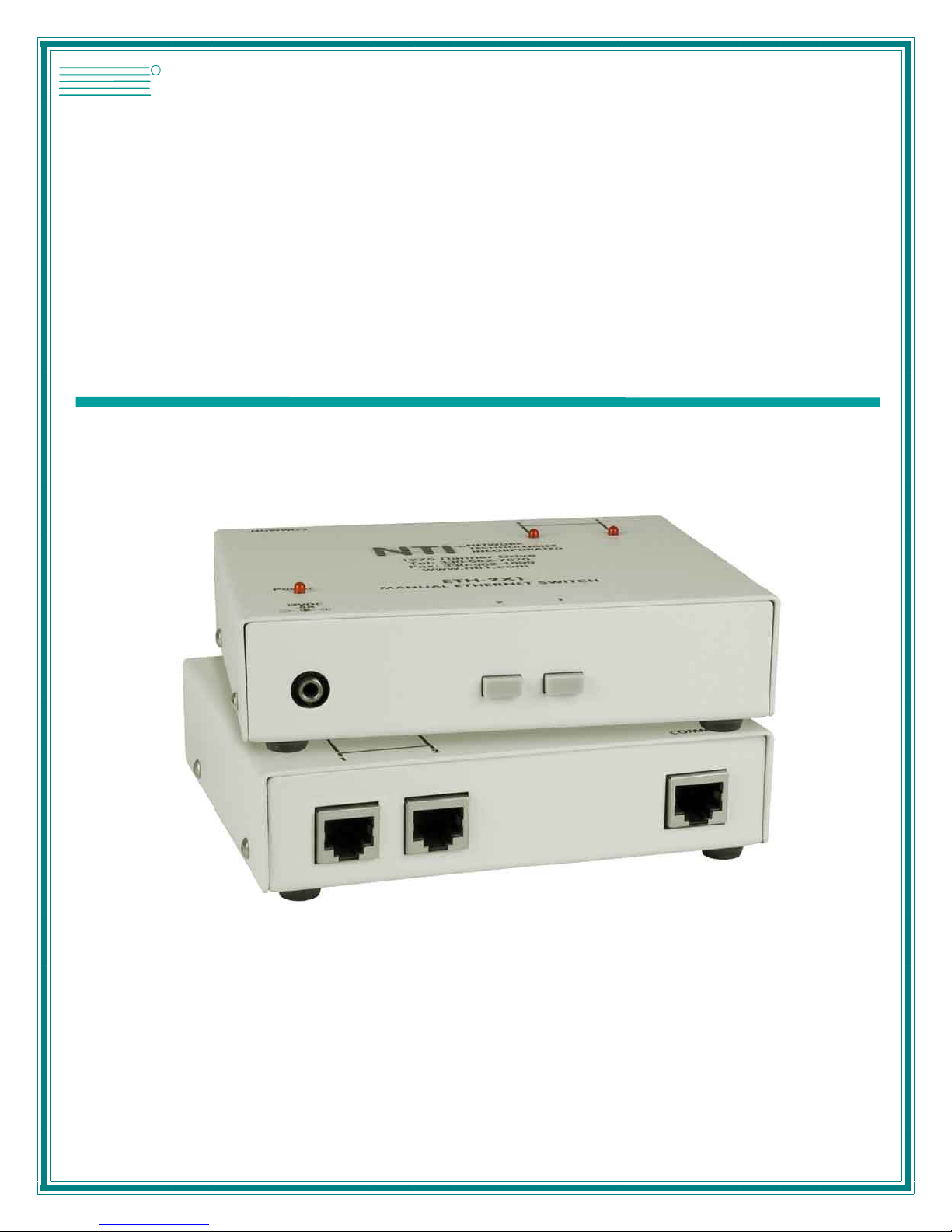
ETH-4X1 / 2X1
Manual Ethernet Switch
Installation and Operation Manual
MAN048 Rev Date 1/13/2005

Warranty Information
The warranty period on this product (parts and labor) is one (1) year from the date of purchase. Please contact Network
Technologies Inc at (800) 742-8324 (800-RGB-TECH) or (330) 562-7070 or visit our website at http://www.nti1.com for
information regarding repairs and/or returns. A return authorization number is required for all repairs/returns.
COPYRIGHT
Copyright © 2005 by Network Technologies Inc. All rights reserved. No part of this publication may be reproduced, stored in a
retrieval system, or transmitted, in any form or by any means, electronic, mechanical, photocopying, recording, or otherwise,
without the prior written consent of Network Technologies Inc, 1275 Danner Drive, Aurora, Ohio 44202.
CHANGES
The material in this guide is for information only and is subject to change without notice. Network Technologies Inc reserves the
right to make changes in the product design without reservation and without notification to its users.
MAN048 Rev Date 1/13/2005

TABLE OF CONTENTS
Introduction......................................................................................................................................................................1
Glossary.......................................................................................................................................................................1
Limitations....................................................................................................................................................................1
Application Examples......................................................................................................................................................2
Materials..........................................................................................................................................................................3
Preparation for Installation ..............................................................................................................................................3
Features and Functions...................................................................................................................................................4
Installation .......................................................................................................................................................................5
Connect the Cables.....................................................................................................................................................5
Plug-in and Boot Up.....................................................................................................................................................6
RS232..........................................................................................................................................................................6
Technical Specifications..................................................................................................................................................7
Interconnection Cable Wiring Method .........................................................................................................................7
Troubleshooting...............................................................................................................................................................8
TABLE OF FIGURES
Figure 1- Connect DEVICE to switch.................................................................................................................................................5
Figure 2- Connect NETWORK to switch............................................................................................................................................5
Figure 3- Connect the AC adapter.....................................................................................................................................................6
MAN048 Rev Date 1/13/2005

NTI Manual Ethernet Switch
INTRODUCTION
The NTI ETH-4X1Manual Ethernet Switch was designed to enable the connection of on e of either four
DEVICEs to one NETWORK or one DEVICE to one of four separate NETWORKs using standard ethernet cable.
The user can control the ETH-4X1 manually to make a single connection active between one NETWORK and one
DEVICE at a time.
Available Options
• Manual Ethernet Switch with 2 user selectable connection ports rather than 4 (ETH-2X1)
• RS232 control to change connections in the ethernet switch via a serial stream (ETH-4X1-RS or
ETH-2X1-RS)
Glossary
NETWORK- Local Area Network (LAN)* , File server, DSL internet connection
CPU- Computer for user access
DEVICE- CPU or other data entry/acquisition equipment
COMMON- A DEVICE or NETWORK that is to be commonly connected to the selected NETWORK or DEVICE
(up to 4) through the ETH-4X1 Manual Ethernet Switch
SELECTABLE- Any NETWORKs or DEVICEs (up to 4) that will be plugged into the user selectable ports
(1-4) and connected to the COMMON through the ETH-4X1 Manual Ethernet Switch
*Note: The ETH-4X1 Manual Ethernet Switch cannot differentiate between LANs and modems. For the purposes of this manual
they will be considered to be identical.
Limitations
All SELECTABLEs must be of the same type (All NETWORKs or all DEVICEs)
If a DEVICE is connected to the "COMMON" port, then only NETWORKs may be connected to the user selectable ports.
If a NETWORK is connected to the "COMMON" port, then only DEVICEs may be connected to the user selectable ports.
1
 Loading...