

Page 1
ENVIROMUX
®
Series
ENVIROMUX-MINI-LXO
Mini Server Environment Monitoring System
Installation and Operation Manual
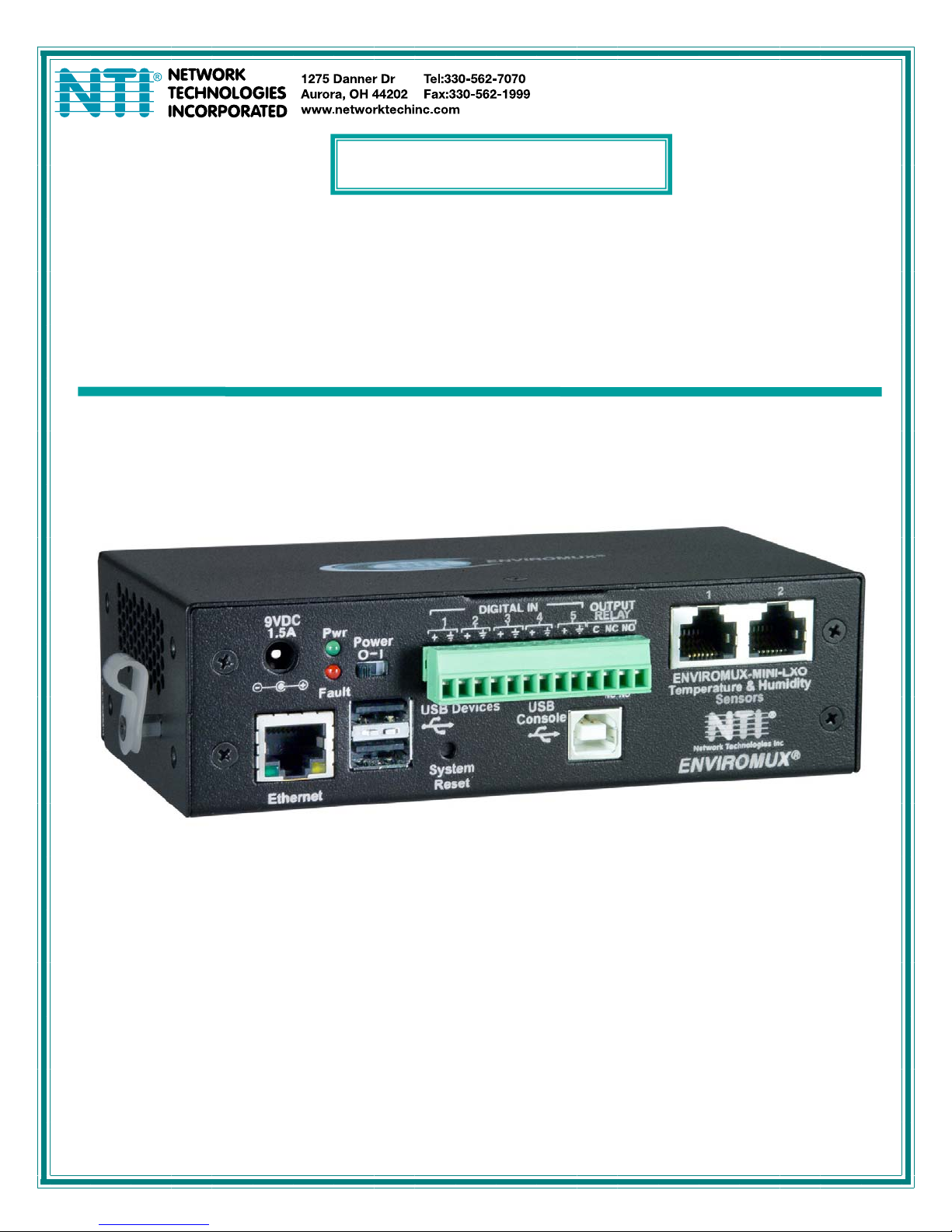
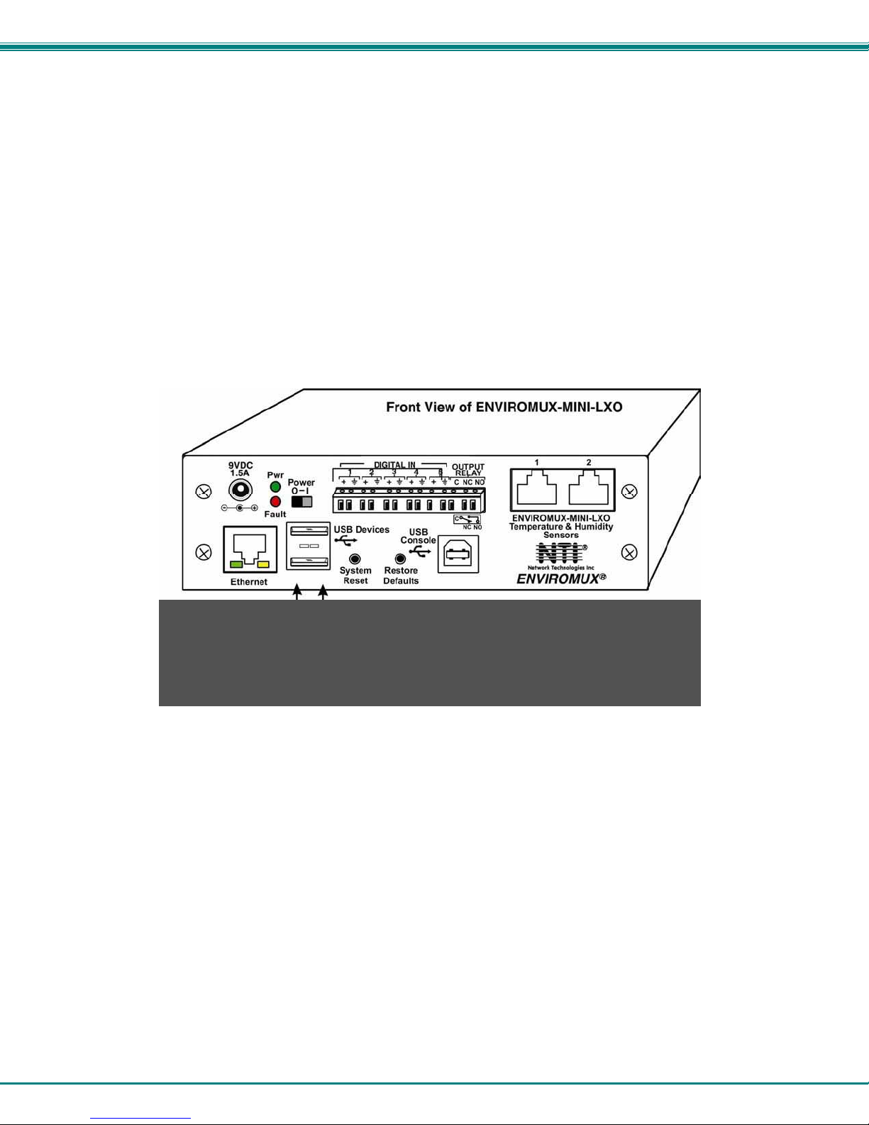
Front View of ENVIROMUX-MINI-LXO
MAN143 Rev Date 12/19/13
Page 2

TRADEMARK
ENVIROMUX is a registered trademark of Network Technologies Inc in the U.S. and other countries.
COPYRIGHT
Copyright © 2009, 2013 by Network Technologies Inc. All rights reserved. No part of this publication may be reproduced, stored
in a retrieval system, or transmitted, in any form or by any means, electronic, mechanical, photocopying, recording, or otherwise,
without the prior written consent of Network Technologies Inc, 1275 Danner Drive, Aurora, Ohio 44202.
CHANGES
The material in this guide is for information only and is subject to change without notice. Network Technologies Inc reserves the
right to make changes in the product design without reservation and without notification to its users.
FIRMWARE VERSION
Current firmware version 1.11
This product contains software licensed under the GNU Public License version 2 and other open source licenses.
( http://www.gnu.org/copyleft/gpl.html
You may obtain the complete open-source code free of charge from Network T echnolog ies Inc (send email to techconsult@ntigo.com) for more information.
)
i
Page 3

TABLE OF CONTENTS
Introduction......................................................................................................................................................................1
Supported Web Browsers ...............................................................................................................................................2
Materials..........................................................................................................................................................................2
Connectors and LEDs.....................................................................................................................................................3
Installation .......................................................................................................................................................................4
Connect Sensors.........................................................................................................................................................4
Output Relay................................................................................................................................................................6
Ethernet Connection....................................................................................................................................................6
USB Console Port........................................................................................................................................................7
Installing Drivers .......................................................................................................................................................7
Using the USB Console Port ..................................................................................................................................12
Connect the Power....................................................................................................................................................13
Front Panel LEDs Indicate Status .............................................................................................................................13
Connect a Modem .....................................................................................................................................................14
Overview........................................................................................................................................................................15
Administration.........................................................................................................................................................15
General Functions...................................................................................................................................................15
Security...................................................................................................................................................................16
Device Discovery Tool...................................................................................................................................................17
Operation via Web Interface..........................................................................................................................................18
Log In and Enter Password .......................................................................................................................................18
Monitoring..................................................................................................................................................................20
Configure Sensors..................................................................................................................................................22
Configure Digital Inputs ..........................................................................................................................................26
Monitor IP Devices..................................................................................................................................................27
Monitor Output Relay..............................................................................................................................................29
Monitor IP Cameras................................................................................................................................................31
DC Power................................................................................................................................................................32
Administration............................................................................................................................................................33
System Configuration .............................................................................................................................................33
Enterprise Configuration.........................................................................................................................................35
Network Configuration............................................................................................................................................36
User Configuration..................................................................................................................................................39
Security...................................................................................................................................................................43
System Information.................................................................................................................................................45
Update Firmware ....................................................................................................................................................46
Reboot the System .................................................................................................................................................47
Smart Alerts...............................................................................................................................................................48
Log.............................................................................................................................................................................55
View Event Log.......................................................................................................................................................55
View Data Log.........................................................................................................................................................56
Log Settings............................................................................................................................................................56
Support ......................................................................................................................................................................58
ii
Page 4

Logout........................................................................................................................................................................58
Operation via Text Menu- ENVIROMUX.......................................................................................................................59
Connect to ENVIROMUX from a Terminal Program.................................................................................................59
Connect to ENVIROMUX from Command Line.........................................................................................................60
Connect Via Telnet .................................................................................................................................................60
Connect Via SSH....................................................................................................................................................60
Using the Text Menu..................................................................................................................................................62
Monitoring...............................................................................................................................................................62
System Configuration .............................................................................................................................................77
Enterprise Configuration.........................................................................................................................................79
Network Configuration............................................................................................................................................79
User Configuration..................................................................................................................................................83
Security Configuration ............................................................................................................................................87
Event and Data Logs..............................................................................................................................................91
System Information.................................................................................................................................................94
Reboot ....................................................................................................................................................................94
Text Menu for Non-Administrative Users...................................................................................................................95
Monitoring...............................................................................................................................................................95
User Accessible Settings........................................................................................................................................97
System Reset Button...................................................................................................................................................101
Restore Defaults Button..............................................................................................................................................101
USB Ports....................................................................................................................................................................101
Wiring Methods ...........................................................................................................................................................102
PC-to ENVIROMUX Crossover Cable.....................................................................................................................102
How To Setup Email....................................................................................................................................................103
Technical Specifications..............................................................................................................................................105
Troubleshooting...........................................................................................................................................................106
Index............................................................................................................................................................................107
Warranty Information...................................................................................................................................................108
Figure 1- Connect Sensors................................................................................................................................................................4
Figure 2- Terminal block for dry-contact sensors...............................................................................................................................4
Figure 3- Secure liquid detection sensor with tape............................................................................................................................5
Figure 4- Portion of Water Sensor configuration page.......................................................................................................................5
Figure 5- Output Relay Application Examples ...................................................................................................................................6
Figure 6- Connect ENVIROMUX-MINI-LXO to the Ethernet..............................................................................................................6
Figure 7- Connect terminal to USB Console port...............................................................................................................................7
Figure 8- COM port assigned to ENVIROMUX................................................................................................................................12
Figure 9- Configure COM port in HyperTerminal .............................................................................................................................12
Figure 10- Connect the AC adapter and power-up..........................................................................................................................13
Figure 11- LEDs on front of ENVIROMUX.......................................................................................................................................13
Figure 12- Connect a Modem ..........................................................................................................................................................14
Figure 13- Device Discovery Tool page...........................................................................................................................................17
Figure 14- Login prompt to access web interface............................................................................................................................18
Figure 15- Summary page...............................................................................................................................................................19
iii
TABLE OF FIGURES
Page 5

Figure 16- Summary page and the Monitoring menu.......................................................................................................................20
Figure 17- Status page for a temperature sensor ............................................................................................................................21
Figure 18- Sensor Configuration page.............................................................................................................................................22
Figure 19- Sensor Configuration- exploded view of additional settings ...........................................................................................23
Figure 20- Chart to setup alert notification.......................................................................................................................................25
Figure 21- Sensor Configuration for Digital Inputs...........................................................................................................................26
Figure 22- IP Devices listing-none monitored yet ............................................................................................................................27
Figure 23- Add New IP Device page................................................................................................................................................27
Figure 24- IP Device Configuration page.........................................................................................................................................28
Figure 25- IP Device list with new devices added............................................................................................................................29
Figure 26- IP Device Status page....................................................................................................................................................29
Figure 27- Output Relay Status .......................................................................................................................................................29
Figure 28- Output Relay Contact State............................................................................................................................................30
Figure 29- Configure Output Relay..................................................................................................................................................30
Figure 30- IP Camera Monitoring.....................................................................................................................................................31
Figure 31- Configure IP Cameras....................................................................................................................................................31
Figure 32- Excerpt from the Summary Page showing DC Power monitoring...................................................................................32
Figure 33- DC Power Alert Configuration.........................................................................................................................................32
Figure 34- System Configuration page ............................................................................................................................................33
Figure 35- Enterprise Configuration- Modem Status “Ready”..........................................................................................................35
Figure 36- No Modem Installed........................................................................................................................................................35
Figure 37- Network Configuration page...........................................................................................................................................36
Figure 38- Network Configuration- more settings ............................................................................................................................37
Figure 39- Users page.....................................................................................................................................................................39
Figure 40- Configure Users page.....................................................................................................................................................39
Figure 41- Configure User- more options.........................................................................................................................................40
Figure 42-Summary page for User without Admin privileges...........................................................................................................42
Figure 43- Security Configuration page ...........................................................................................................................................43
Figure 44- Security Configuration- IP Filtering Rules.......................................................................................................................44
Figure 45- System Information page................................................................................................................................................45
Figure 46- Update Firmware page...................................................................................................................................................46
Figure 47- Reboot System page......................................................................................................................................................47
Figure 48- System is rebooting........................................................................................................................................................47
Figure 49- Events used for Smart Alerts..........................................................................................................................................48
Figure 50- Sensor to be used for a predefined event.......................................................................................................................48
Figure 51- Configuration options for new event...............................................................................................................................49
Figure 52- Smart Alert summary page.............................................................................................................................................50
Figure 53- Smart Alert configuration................................................................................................................................................51
Figure 54- Event Logical Function Diagram.....................................................................................................................................53
Figure 55- Examples of Smart Alert conditions................................................................................................................................54
Figure 56- Event Log page ..............................................................................................................................................................55
Figure 57- Data Log page................................................................................................................................................................56
Figure 58- Log Settings page...........................................................................................................................................................57
Figure 59- Support...........................................................................................................................................................................58
Figure 60- Logout ............................................................................................................................................................................58
Figure 61- Text Menu Login screen.................................................................................................................................................59
Figure 62- Text Menu- Administrator Main Menu.............................................................................................................................60
Figure 63- Text Menu- User Main Menu..........................................................................................................................................61
Figure 64- Text Menu-Monitoring Menu...........................................................................................................................................62
Figure 65- Text Menu-Sensor Status...............................................................................................................................................63
Figure 66- Text Menu- Digital Input Status ......................................................................................................................................63
iv
Page 6

Figure 67- Text Menu-View IP Devices............................................................................................................................................64
Figure 68- Text Menu- View Output Relay Status............................................................................................................................64
Figure 69- Text Menu-Configure Sensors list ..................................................................................................................................65
Figure 70- Text Menu-Configuration Menu for Sensor.....................................................................................................................65
Figure 71- Text Menu-Sensor Settings............................................................................................................................................66
Figure 72- Text Menu-Non-Critical and Critical Alert Settings..........................................................................................................67
Figure 73- Text Menu-Sensor Data Logging....................................................................................................................................68
Figure 74- Configure Digital Input Sensors......................................................................................................................................68
Figure 75- Digital Input Sensor Settings Menu ................................................................................................................................69
Figure 76- Digital Input Alert Settings ..............................................................................................................................................69
Figure 77- Data Logging for Digital Input Sensors...........................................................................................................................70
Figure 78- Text Menu-Configure IP Devices List.............................................................................................................................71
Figure 79- Text menu-Configuration Menu for IP Devices...............................................................................................................71
Figure 80-Text Menu-IP Device Settings.........................................................................................................................................72
Figure 81- Text Menu-IP Device Alert Settings................................................................................................................................73
Figure 82- Text Menu-IP Device Data Logging................................................................................................................................74
Figure 83- Text Menu- Select Configure Output Relay....................................................................................................................74
Figure 84- Text Menu- Output Relay Settings..................................................................................................................................75
Figure 85- Text Menu- Output Relay Alert Settings .........................................................................................................................75
Figure 86- Text Menu- IP Camera List for Configuration .................................................................................................................76
Figure 87- Text Menu- IP Camera Settings .....................................................................................................................................76
Figure 88- Text Menu- System Configuration..................................................................................................................................77
Figure 89- Text Menu-Time Settings menu......................................................................................................................................77
Figure 90- Text Menu-Restore Default Settings...............................................................................................................................78
Figure 91- Text Menu-Enterprise Configuration...............................................................................................................................79
Figure 92- Text Menu-Network Configuration..................................................................................................................................79
Figure 93- Text Menu-IPv4 Settings Menu ......................................................................................................................................80
Figure 94- Text Menu-IPv6 Settings Menu ......................................................................................................................................80
Figure 95- Text Menu-SMTP Server Settings..................................................................................................................................81
Figure 96- Text Menu-SNMP Server Settings..................................................................................................................................81
Figure 97- Text Menu-Misc. Service Settings menu ........................................................................................................................82
Figure 98- Text Menu-User Configuration........................................................................................................................................83
Figure 99- Text Menu-Confirm to add new user ..............................................................................................................................83
Figure 100- Text Menu-Configuration List for User..........................................................................................................................84
Figure 101- Text Menu-User Account Settings................................................................................................................................84
Figure 102- Text Menu-User Contact Settings.................................................................................................................................85
Figure 103- Text Menu-User Activity Schedule................................................................................................................................86
Figure 104-Text Menu- SNMP User Settings...................................................................................................................................86
Figure 105- Text Menu-Security Configuration ................................................................................................................................87
Figure 106- Text Menu-Authentication Settings ...............................................................................................................................88
Figure 107- Text Menu-IP Filtering..................................................................................................................................................89
Figure 108- Text Menu-Configure IP Filter rule................................................................................................................................89
Figure 109- Text Menu-Event & Data Logs......................................................................................................................................91
Figure 110- Text Menu-View Event Log...........................................................................................................................................91
Figure 111- Text Menu-View Data Log............................................................................................................................................92
Figure 112- Text Menu-Event Log Settings .....................................................................................................................................93
Figure 113-Text Menu-Data Log Settings........................................................................................................................................93
Figure 114-Text Menu-System Information......................................................................................................................................94
Figure 115- Text Menu-Reboot the ENVIROMUX...........................................................................................................................94
Figure 116- Text Menu-User Main Menu......................................................................................................................................... 95
Figure 117-Text Menu-User Monitoring Menu .................................................................................................................................95
v
Page 7

Figure 118- Text Menu-User accessible status menus....................................................................................................................96
Figure 119- Text Menu-User Accessible Settings............................................................................................................................97
Figure 120- Text Menu-User Account Settings................................................................................................................................97
Figure 121- Text Menu-User Contact Settings.................................................................................................................................98
Figure 122- Text Menu-User Activity Schedule................................................................................................................................99
Figure 123- Text Menu-User SNMP Settings...................................................................................................................................99
Figure 124- Location of Reset buttons...........................................................................................................................................101
Figure 125- USB Flash Drive and GSM modem ports...................................................................................................................101
Figure 133- Example of configuration for Gmail server..................................................................................................................103
Figure 134- Configure user to receive alerts via email...................................................................................................................104
vi
Page 8

NTI Mini Server Environment Monitoring System
INTRODUCTION
The ENVIROMUX-MINI-LXO (ENVIROMUX) are Server Environment Monitoring Systems designed to monitor, from a remote
location, the critical environmental conditions in cabinets and rooms containing servers, hubs , switches and other network
components. Remote monitoring is provided via a 10/100BaseT Ethernet web interface, secure web interface, SSH, or Telnet.
The input data is filtered, collected, analyzed and processed to allow the user to configure it to meet individual requirements. The
user is able to specify parameters for all monitored signals. When a sensor exceeds the configured threshold, the unit will signal
an alert. Alert methods include email, SMS, SNMP traps (MIBs), web-page alerts, and a visual indicator (red LED).
The ENVIROMUX-MINI-LXO will monitor temperature, humidity, and detect the presence of water on a flat surface (such as the
floor). The unit also has four sets of terminal block pairs for the connection of contact-closure sensors.
Features and Applications
¾ Monitor and manage server room environmental conditions over IP.
¾ Monitors and operates at temperatures from 32°F to 122°F (0ºC and 50ºC) and 20% to 90% relative humidity.
¾ Optional Industrial version (ENVIROMUX-MINI-LXO-IND) operates at 32 to 167°F (0 to 75°C).
¾ Sensors supported:
• 2 temperature/humidity sensors
• 5 digital input devices
¾ Operates and configures via HTTP web page.
¾ 4 remote users can access the system simultaneously.
¾ Supports SMS alert messages via GSM modem
¾ Supports SMTP protocol
¾ Supports SNMP V1, V2C and V3 protocols
¾ Supports Microsoft Internet Explorer 6.0 and higher, Firefox 2.0 and higher, Chrome, Safari 4.0 or higher, and Opera 9.0
¾ Sensor alerts and log messages are sent using email, Syslog, and SNMP traps when any monitored environmental
condition exceeds a user-specified range.
¾ Sensor alerts, end of alerts, and log-ins are posted in message log, which is accessible through web interface.
¾ SNMP trap messages can be imported into Microsoft Excel
¾ Use in data centers, co-lo sites, web hosting facilities, telecom switching sites, POP sites, server closets, or any
unmanned area that needs to be monitored.
¾ Security: HTTPS, SSHv2, SSLv3, IP Filtering, LDAPv3, AES 256-bit encryption, 3DES, Blowfish, RSA, EDH-RSA,
Arcfour, SNMPv3, IPV6, SNTP support,16-character username/password authentication, user account restricted access
rights.
¾ Monitor (ping) up to 16 IP network devices.
o Configure the timeout and number of retries to classify a device as unresponsive.
o Alerts are sent if devices are not responding.
¾ Monitored sensors and devices can be individually named (up to 63 characters).
¾ Monitor environmental conditions.
o Supports two sensors, including: temperature, humidity, up to 5 dry contacts or water detection sensors.
o When a sensor goes out of range of a configurable threshold, the system will notify you via email, syslog, LEDs,
web page, and network management (SNMP).
¾ Operates on a Linux system.
¾ Firmware upgradeable "in-field" through Ethernet port..
¾ Output relay fo
¾ Monitor up to 8 IP cameras
Options:
¾ The ENVIROMUX can be ordered with a DIN rail mounting bracket- Add “D” to the part number
(i.e. ENVIROMUX-MINI-LXO-D)
¾ The ENVIROMUX can be ordered with battery backup support and DC power monitoring installed, providing up to 2.3
hours of operation in the event of a power failure- to order, add “B” to the part number (i.e. ENVIROMUX-MINI-LXOB)
¾ The ENVIROMUX can be ordered with a higher operating temperature range (32 to 167°F (0 to 75°C))- to order add “-
IND” to the part number (i.e. . ENVIROMUX-MINI-LXO-IND)
r control of externa
l device (contacts rated for up to 1A, 30VDC or 0.5A, 125VAC)
1
Page 9

NTI Mini Server Environment Monitoring System
SUPPORTED WEB BROWSERS
Most modern web browsers should be supported. The following browsers have been tested:
• Microsoft Internet Explorer 6.0 or higher
• Mozilla FireFox 2.0 or higher
• Opera 9.0
• Google Chrome
• Safari 4.0 or higher for MAC and PC
MATERIALS
Materials supplied with this kit:
• NTI ENVIROMUX-MINI-LXO Mini Server Environment Monitoring System
• 1- 120VAC or 240VAC at 50 or 60Hz-9VDC/1.5A AC Adapter (PS4074)
• 1- Line cord- country specific
• 1- USB2-AB-2M-5T 2 meter USB 2.0 male type A-male type-B transparent cable (CB4306)
• CD containing a pdf of this manual, a SNMP MIB file, and the NTI Discovery Tool
Additional materials may need to be ordered;
CAT5/5e/6 unshielded twisted-pair cable(s) terminated with RJ45 connectors wired straight thru- pin 1 to pin 1, etc. for Ethernet
connection
Contact your nearest NTI distributor or NTI directly for all of your cable needs at 800-RGB-TECH (800-742-8324) in US & Canada
or 330-562-7070 (Worldwide) or at our website at http://www.networktechinc.com
and we will be happy to be of assistance.
2
Page 10
NTI Mini Server Environment Monitoring System
CONNECTORS AND LEDS
#
LABEL CONNECTOR/LED DESCRIPTION
Pwr
1
Fault
2 USB Console
3 Ethernet
4 9V 1.5A
5 Temperature &
Humidity
Sensors
6 DIGITAL IN
7 OUTPUT RELAY
8 Power
9 USB Devices
10 System Reset
11 Restore Defaults
Green LED
Red LED
USB Type B female connector For connection of terminal for control through Text Menu
RJ45 female connector for connection to an Ethernet for remote multi-user control and
2.1x5.5mm Power Jack for connection of power supply
RJ45 female connectors for connection of optional ENVIROMUX-T, ENVIROMUX-RH, or
Wire terminal block For connecting dry-contact and liquid detection sensors
Wire terminal block For control of external devices (contacts rated up to 1A, 30VDC or
Slide switch For powering the ENVIROMUX On (I) and Off (O)
USB Type A female
connectors
Push button For manually rebooting the ENVIROMUX without power-cycling- a
Push button For manually restoring the ENVIROMUX to factory default settings-
green — indicates device is powered
red — illuminates if a sensor goes out of range of a configurable
threshold
monitoring
• Yellow LED- indicates 100Base-T activity when illuminated,
• Green LED – illuminated when Ethernet link is present, strobing
ENVIROMUX-TRH sensors (The left port is "#1", the right port is
"#2" as listed in the Summary Page on Page 19.)
0.5A, 125VAC)
For connecting USB Flashdrive and USB Modem
momentary press will activate
press and hold for 5 seconds to activate
10Base-T activity when dark
indicates activity on the Ethernet port
3
Page 11
NTI Mini Server Environment Monitoring System
INSTALLATION
Connect Sensors
Connect the desired sensors (sold separately) to the available ports on the ENVIROMUX. Plug the RJ45 connectors to either of
the two RJ45 ports marked "TEMPERATURE/HUMIDITY". Mount the sensors according to their individual operating
characteristics. Power-cycle the ENVIROMUX after sensors have been plugged-in.
Note: The maximum CAT5 cable length for attachment of temperature and humidity sensors in the
ENVIROMUX-MINI-LXO is 25 feet.
Note: Mounting the temperature sensor in the path of a fan or on a heated surface may affect the accuracy of the
sensor’s readings.
Figure 1- Connect Sensors
Up to five dry-contact sensors can also be connected. Sensors with 16-26 AWG connection wires, that operate on 5V at 10mA
maximum current may be used. A contact resistance of 10kΩ or less will be interpreted by the ENVIROMUX as a closed contact.
The maximum cable length for attachment of contact sensors is 1000 feet.
To install the dry-contact sensor(s) to “DIGITAL IN” terminals:
A. Attach the positive lead to a terminal corresponding to a "+" marking on the ENVIROMUX and the ground lead
to the next terminal to the right that will correspond to a marking on the ENVIROMUX. Tighten the set
screw above each contact. Terminal sets are numbered 1-5.
B. Mount the sensors as desired.
Figure 2- Terminal block for dry-contact sensors
Note: The terminal block is removable for easy sensor wire attachment if needed.
4
Page 12
NTI Mini Server Environment Monitoring System
Optionally, connect the two-wire cable from a liquid detection
sensor (ENVIROMUX-LD shown below- sold separately) to a set
of “DIGITAL IN” contacts.
The twisted orange sensing cable should be placed flat on the
surface (usually the floor) where liquid detection is desired. If
tape is required to hold the sensor in place, be sure to only apply
tape to the ends, exposing as much of the sensor as possible. At
least 5/8" of the sensor must be exposed for it to function. (See
Figure 3)
Figure 3- Secure liquid detection sensor with tape
To test the ENVIROMUX-LD;
1. Configure the sensor (page 26). (Normal Status set to “Open”, Refresh Rate set to 5 seconds.)
2. Submerge at least ½ inch of the exposed twisted orange wire (not the wrapped end) for up to 30 seconds. Do NOT use
distilled water as water must be conductive.
3. Monitor the sensor (page 20) to see the sensor “Value” change from “Open” (dry) to “Closed” (wet).
4. Dry the exposed area of sensor and the sensor “Value” should change back to “Open” within 30 seconds.
Figure 4- Portion of Water Sensor configuration page
5
Page 13
NTI Mini Server Environment Monitoring System
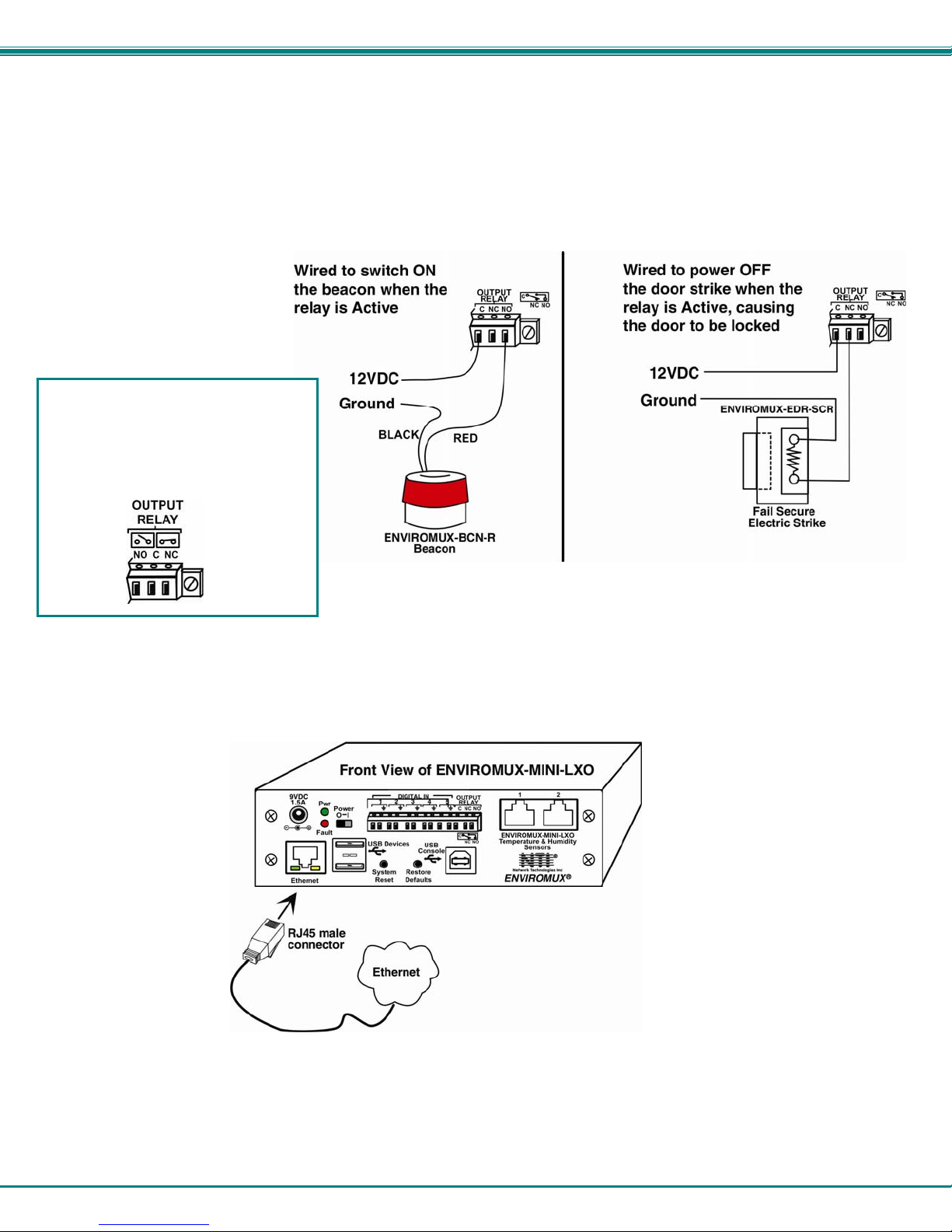
Output Relay
An output relay is provided to control an external device with a rating of up to 1A, 30VDC or 0.5A, 125VAC. Three terminals are
provided to enable a normally-open connection (using the N.O. and C terminals) or a normally-closed connection (using the N.C.
and C terminals). Using the web interface, this relay can be set to change state (close the normally-open connection, or open
the normally-closed connection) either manually (page 29) or as a result of an alert state from one or more of the connected
sensors (page 22). The terminals for these connections will accept 16-26AWG wire.
Note: A recent design improvement
resulted in a change to the pinout of
the output relay in the ENVIROMUXMINI-LXO. Please be aware of the
change and note which version yours
is. The previous version is shown
below.
Figure 5- Output Relay Application Examples
Ethernet Connection
Connect a CAT5 patch cable (RJ45 connectors on each end wired pin 1 to pin 1, pin 2 to pin 2 etc) from the local Ethernet
network connection to the connector on the ENVIROMUX marked "Ethernet".
Figure 6- Connect ENVIROMUX-MINI-LXO to the Ethernet
Note: A direct Ethernet connection can be made with a PC using a crossover cable. For the pinout of this cable, see
page 102.
6
Page 14
NTI Mini Server Environment Monitoring System
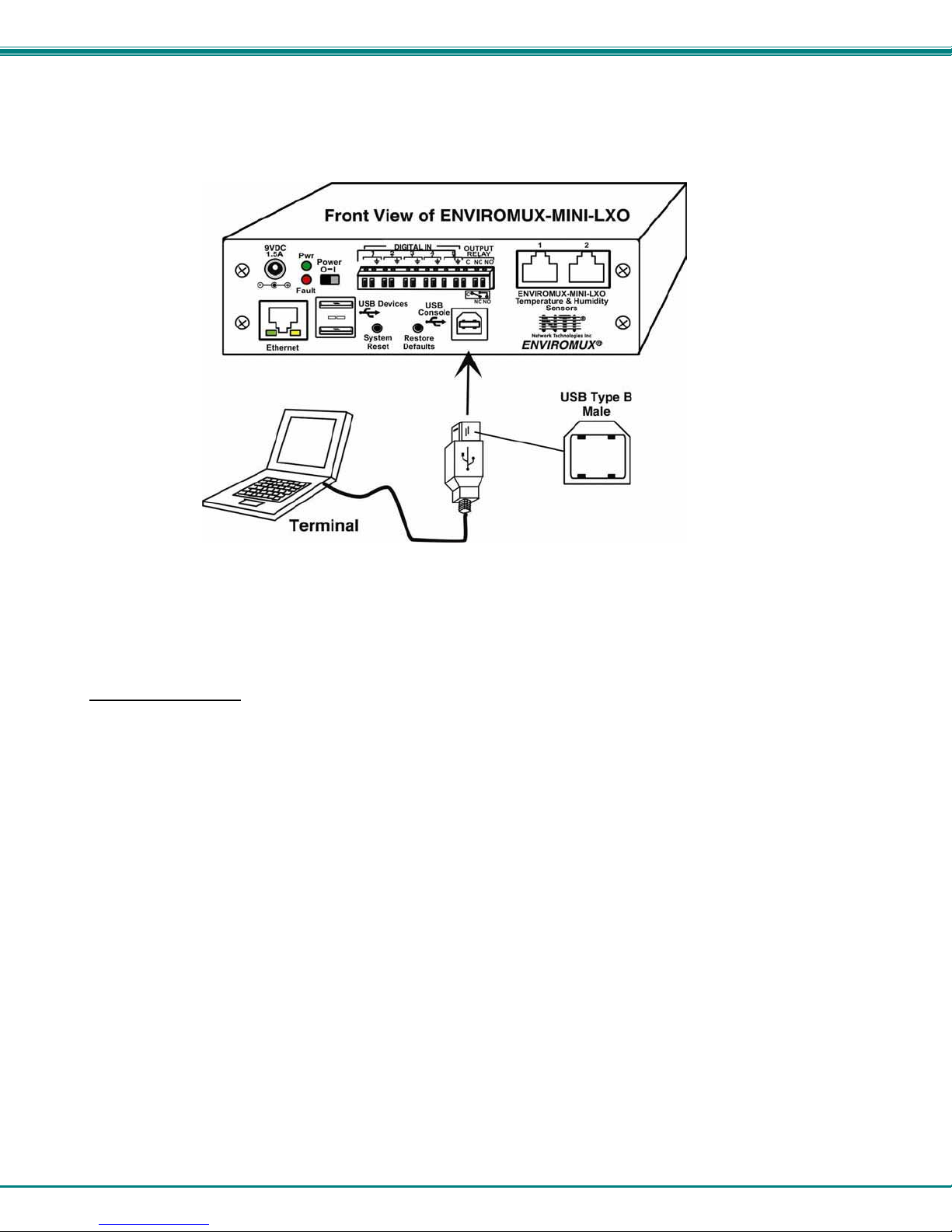
USB Console Port
Your ENVIROMUX includes a USB Type B connector labeled “USB Console”. If you connect a USB cable between the
ENVIROMUX and your PC you will be able to control your ENVIROMUX serially from a terminal console using this connection.
Figure 7- Connect terminal to USB Console port
Installing Drivers
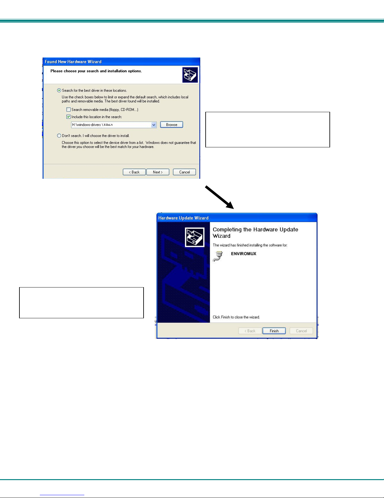
You will only need to install drivers the first time the ENVIROMUX is connected to your PC. After the first time, when the
ENVIROMUX is connected, your PC should recognize the ENVIROMUX and re-assign the COM port. Follow the steps below to
install the drivers.
1. Make sure the USB cable is connected between the ENVIROMUX and your PC.
2. Power ON the ENVIROMUX. The PC will see the ENVIROMUX as “New Hardware” and create a virtual COM port to
communicate with it.
3. You will be prompted to load drivers. A driver file compatible with Windows XP, 2000, Vista and 7 (32 and 64 bit versions) can
be found on the CD that came with your ENVIROMUX. Browse to the drive your Product Manual CD is in and locate and sel ect
the file named “enviromux.inf” in a directory named “windows-drivers\32bit or \64bit” depending upon your
operating system.
The .inf file will direct your PC to locate and install the file usbser.sys (already on your PC, comes with Windows). Installing
the usbser.sys file should happen automatically. When finished, Windows will indicate in stallation is successful.
7
Page 15
NTI Mini Server Environment Monitoring System
A
Windows XP-32 bit Installation
Your typical installation will include windows like the ones that follo w. The images bel ow are from a Windows XP SP2 32 bit
installation.
B. You can try to “Install the software
automatically” but if windows doesn’t check
the CD, you will need to use “Install from a
list or specific location” instead.
. Windows will want to check the internet
for drivers. Choose “No, not this time”
because the drivers are unique to the
ENVIROMUX.
8
Page 16
NTI Mini Server Environment Monitoring System
D. Once the driver is installed, you will get
this screen and the ENVIROMUX USB
Console Port will be ready to use.
C. Let the New Hardware Wizard search for
the driver, but direct it to the drive the Product
Manual CD is in and the directory of either
the 32 bit driver or the 64 bit driver.
9
Page 17
NTI Mini Server Environment Monitoring System
D
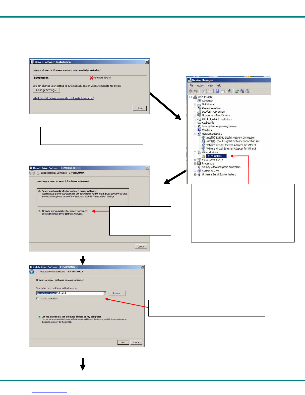
Windows 7-64 bit Installation
A Windows 7 64 bit installation has a few extra steps. The images below are from a Windows 7, 64-bit installation.
A. Upon ENVIROMUX power ON, the driver
cannot be found. Press “Close”.
C. From the next window,
select “Browse my
computer for driver
software”.
. In the next window, enter the path to the .inf driver
file (on the Product Manual CD). Press “Next”.
B. Open the Device Manger and select the
ENVIROMUX in the device list. Right-click and
open “Properties”. Select “Update Driver
Software”.
Tip: The Device Manager can be opened by
right-clicking on “My Computer” on the
desktop, selecting “Properties”, and
selecting “Device Manager”.
10
Page 18
NTI Mini Server Environment Monitoring System
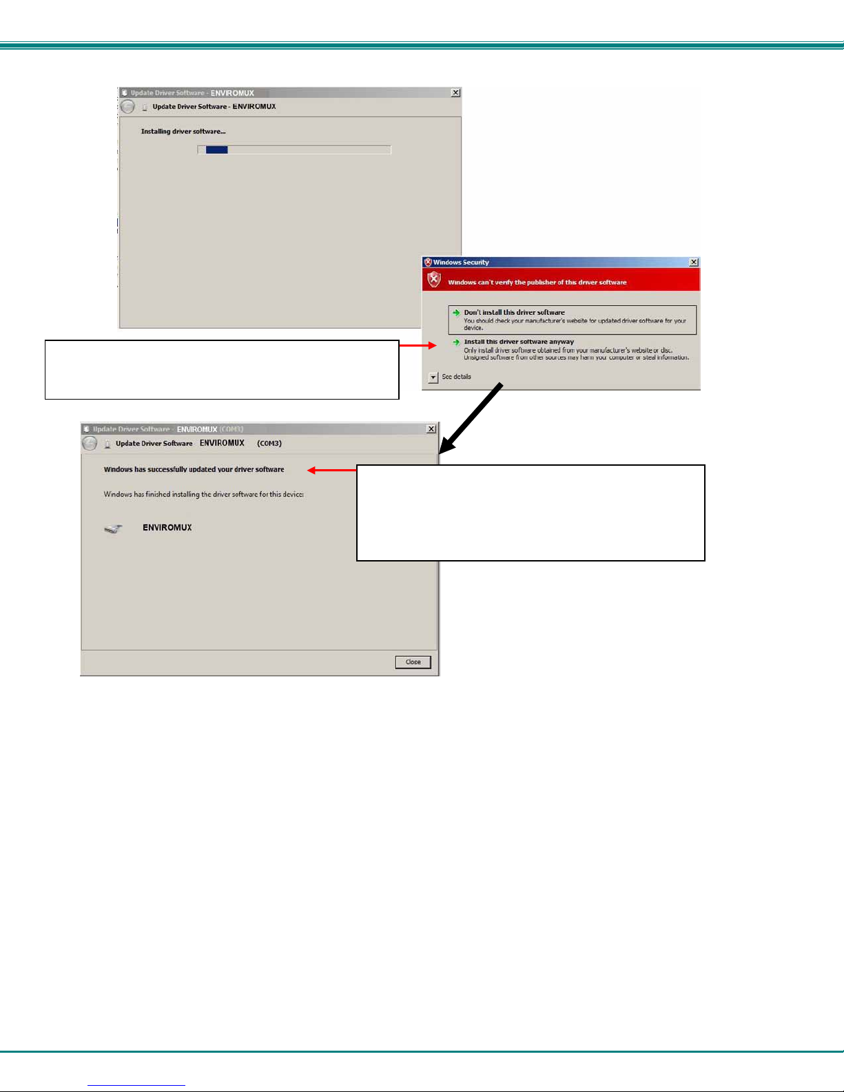
E. You will probably get this warning that Windows can’t
verify the publisher of the driver software. Select “Install
this driver software anyway. “
F. The driver will load. This might take a minute while it
searches your computer for the usbser.sys file it needs.
Once it does, you will get a window telling you Windows is
finished. Take note of the COM port number it assigned.
(This one assigned COM3.)
11
Page 19
NTI Mini Server Environment Monitoring System
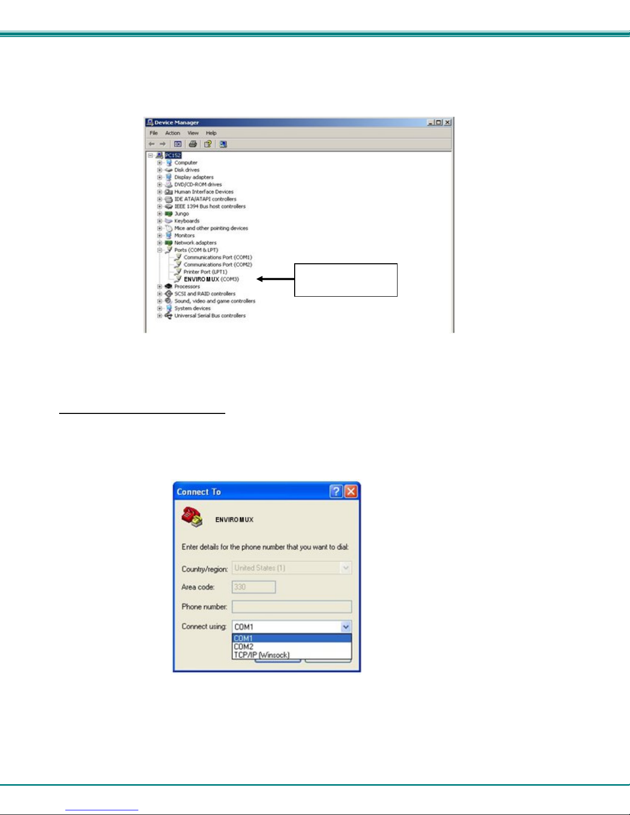
4. During the installation, your PC will assign a COM port number to the USB port attached to the ENVIROMUX. You will need
to identify the COM port number assigned. This information can be viewed in your Device Manager list (below) if you didn’t take
note of it during installation.
COM Port
Assignment
Figure 8- COM port assigned to ENVIROMUX
Using the USB Console Port
The virtual COM port will be used to enable serial control over the ENVIROMUX (see Operation Via Text Menu on page 59).
When you open a terminal program be sure to use the correct COM port (see Figure 8 and Figure 9 ).
Figure 9- Configure COM port in HyperTerminal
12
Page 20
NTI Mini Server Environment Monitoring System
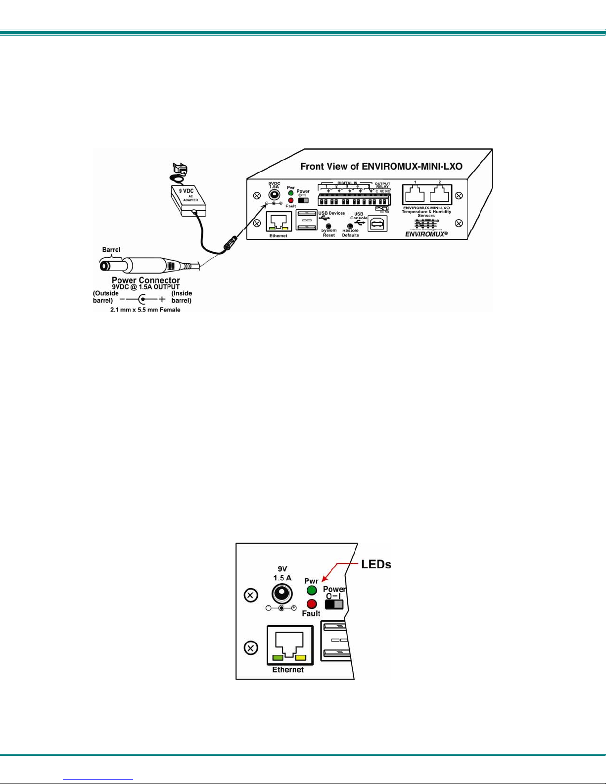
Connect the Power
Note: Sensors should be connected before supplying power to the ENVIROMUX.
1. Connect the AC adapter to the connection marked "PWR" on the ENVIROMUX and plug it into an outlet.
Figure 10- Connect the AC adapter and power-up
2. Use the NTI Discovery Tool (page 17) to configure network settings.
Front Panel LEDs Indicate Status
With proper connections made, the ENVIROMUX is now ready to power ON. With the power cord attached and plugged into an
AC outlet, the “Power” green LED should be illuminated on the front of the ENVIROMUX. The red “Fault” LED will illuminate
when power is first applied and while the ENVIROMUX boots up (for up to 60 seconds). Once the red LED goes OFF, the
ENVIROMUX is ready for use. After a completed boot-up, the red LED will only illuminate when one of the connected sensors is
in alert.
Figure 11- LEDs on front of ENVIROMUX
13
Page 21
NTI Mini Server Environment Monitoring System
Connect a Modem
A USB GSM modem may be connected (ENVIROMUX-3GU) to use to send SMS alert messages to a contact’s cell phone. The
ENVIROMUX-3GU modem will connect to the ENVIROMUX at the “USB Devices” port (either USB Type A connector, it doesn’t
matter which one) . The remaining USB Type A connector on the ENVIROMUX is available for the connection of a USB Flash
Drive for data logging (page 57).
The phone number to be called for each user is configured under “User Configuration-Contact Settings” (page 41).
Note: A Mini SIM card (not included) must be installed in the modem for the modem to send messages. Make sure the
SIM card is for GSM communication (not CDMA) and that it is not locked (some SIM cards are "locked" to search for a
specific IMEI number of the phone to operate).
Figure 12- Connect a Modem
Cell phone Mini SIM card for GSM modem
A SIM card or Subscriber Identity Module is a portable memory chip used in some models of cellular telephones. It can be thought
of as a mini hard disk that automatically activates the phone (or in this case the GSM modem) into which it is inserted.
SIM cards are available in two standard sizes. The first is the size of a credit card (85.60 mm × 53.98 mm x 0.76 mm). The newer,
more popular miniature-version has a width of 25 mm, a height of 15 mm, and a thickness of 0.76 mm.
Some cellular service providers use Mini SIM cards. Verify with your service provider that their Mini SIM card will work with GSM
/ 3G GSM modems before making a purchase.
Note: The ENVIROMUX-3GU will send SMS messages only. No access to the ENVIROMUX is possible through the
modem.
14
Page 22

NTI Mini Server Environment Monitoring System
OVERVIEW
Administration
The ENVIROMUX can be administered in any one of the following ways:
• Using Telnet or SSH protocol via the Ethernet Port.
• Using a terminal program via the USB Console Port
• Using the web interface (HTTP/HTTPS protocol) via the Ethernet Port.
The following administrative controls are available in the ENVIROMUX, thru the menu.
• View or modify the administrator & user parameters (passwords, sensor alert subscriptions, admin access, etc.)
• View or modify the network parameters (e.g. IP Address, Gateways, DNS, etc.)
• View and clear system event logs
• Clear, import, export and restore configuration parameters
• Firmware upgrades for the ENVIROMUX (over Ethernet)
• View or modify sensor, and IP device configurations
General Functions
Sensor Alerts
A high and low threshold limit can be set for each temperature or humidity sensor. When a sensor takes a reading that is outside
a threshold, an alert notification is generated. The user can specify the frequency of alert notifications to match his or her
schedule. Also, there will be some hysteresis involved with alert notifications. This means if a sensor’s readings are moving in
and out of the threshold boundaries within a configurable period of time, additional alert notifications wil l not be sent. After an alert
is activated, it remains persistent even if the condition of the sensors returns back to normal, until the user acknowledges or
dismisses that alert. The user has the option to set the unit to auto-clear the alert if the sensor’s status returns to normal, and the
user can be notified if the condition goes back to normal. Alert notifications will be provided through four main methods: visible
notification via one of the user interfaces (red “Fault” LED on front panel, alert on webpage, alert in text menu), emails, syslog
message and/or SNMP traps.
IP Monitoring & Alerts
Individual IP addresses can be monitored. The ENVIROMUX will ping each address, and if a response is received, the IP
address status is considered to be “OK”’. If no response, the user will have the option to configure the ENVIROMUX for an alert
will be logged and sent. The user can configure the timeout for a response and the number of retries before signaling an alert.
The ENVIROMUX can also be configured to monitor the IP addresses of the network switches and routers to which these devices
are connected, so as to determine if the problem is due to a lack of response from the device or a network failure. Alert
notifications will be provided through four main methods: visible notification via one of the user interfaces (red “Fault” LED on front
panel, alert on webpage, alert in text menu), emails, syslog messages, SMS messages and/or SNMP traps.
Event Log
The ENVIROMUX maintains an event log. The event log includes power-ON, system, and alert notifications, as well as user
login/logout, and user alert handling. The maximum number of log entries is 1000, and these entries are sorted in chrono logical
order. The log can be viewed at any time through the web interface or text menu, and can be saved as a text file. Log entries can
be removed individually or all at once.
Data Log
The ENVIROMUX maintains a data log. The data log includes readings taken from sensors, IP devices, and connected
accessories being monitored. The maximum number of log entries is 1000, and these entries are sorted in chronological order.
The log can be viewed at any time through the web interface or text menu, and can be saved as a text file. Log entries can be
removed individually or all at once.
15
Page 23

NTI Mini Server Environment Monitoring System
Email
The ENVIROMUX can access an SMTP server to send outgoing email. Outgoing email would contain pre-formatted alert
notifications. SMTP server information can be configured using one of the interfaces. Email addresses can be configured through
web pages or text menu. Each user (up to 15) can have their own email address. For assistance in setting up Email, see page
103.
The email messages sent by the ENVIROMUX have a fixed format. Alert emails contain 6 fields and will have a configurable title.
The title is configurable for each sensor, device, or IP address. The title is the “email subject” in all configuration pages. A
sample message is shown below:
ENTERPRISE: Enterprise name here
LOCATION: Danner Drive
CONTACT: John Smith
DESCRIPTION: Undefined #5
TYPE: Humidity
MESSAGE: Sensor value exceeded thresholds
SNMP
The ENVIROMUX can send alerts as SNMP traps when a sensor or IP device enters/leaves alert mode and for all log events.
Using an SNMP MIB browser, a user can monitor all sensor statuses and system IP settings.
The destination for SNMP traps can be configured for each user.
Note: The SNMP MIB file (mini-lx-v1-xx.mib), for use with an SNMP MIB browser or SNMP trap receiver, can be found on
the manual CD. Click on the link to open the file, then save the file to your hard drive to use with the SNMP MIB browser
or SNMP trap receiver.
GSM Modem
An external GSM modem can be connected to allow the system to send alert notifications via SMS messages. When a sensor
crosses a threshold or IP device become inactive, an alert notification can be formatted to SMS message (see page 24) and the
modem can transmit the message to all users that subscribe to the applicable sensor group.
Security
User Settings
In order to configure and operate the ENVIROMUX, each user must login with a unique username and password. The
Administrator can configure each user’s settings as User or Administrator. An Administrator has access to all configurations and
controls. A user can monitor sensors, accessories, and IP devices. A user can edit his/her own account. Users cannot configure
the sensor settings.
IP Filtering
The ENVIROMUX allows the administrator to block access to the device from certain IP addresses. The ENVIROMUX can accept
or drop requests based on the IP filter settings. IP Filtering provides an additional mechanism for securing the ENVIROMUX.
Access to the ENVIROMUX network services (SNMP, HTTP(S), SSH, Telnet) can be controlled by allowing or disallowing
connections from various IP addresses, subnets, or networks.
Secure Connections
The ENVIROMUX supports secure connections using SSHv2 and HTTPS.
Authentications
The ENVIROMUX supports local authentication with up to 16 character usernames and passwords, and it also supports LDAPv3.
Encryption
The ENVIROMUX supports 256-bit AES encryption.
16
Page 24
NTI Mini Server Environment Monitoring System
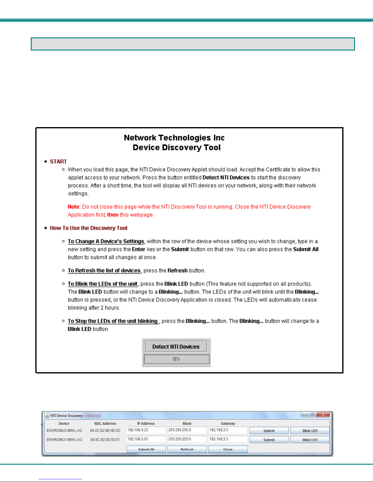
DEVICE DISCOVERY TOOL
In order to easily locate the ENVIROMUX on a network, the NTI Device Discovery Tool may be used. A link to the Discovery
Tool is provided on the web page that appears when you insert the instruction manual CD provided into your CD ROM drive.
Click on the link or browse the CD and click on the file discover.html . This will open your browser and display the Device
Discovery Tool page.
Note: The Device Discovery Tool requires the Java Runtime Environment to operate. A link to the web page from which
it can be downloaded and installed is provided on the CD.
Note: The computer using the Device Discovery Tool and the ENVIROMUX must be connected to the same physical
network in order for the Device Discovery Tool to work.
Figure 13- Device Discovery Tool page
Use the Device Discovery Tool to display all NTI ENVIROMUX units on the network, along with their network settings. Follow the
instructions on the Device Discovery Tool page to use the tool and to change the device settings if so desired.
17
Page 25
NTI Mini Server Environment Monitoring System
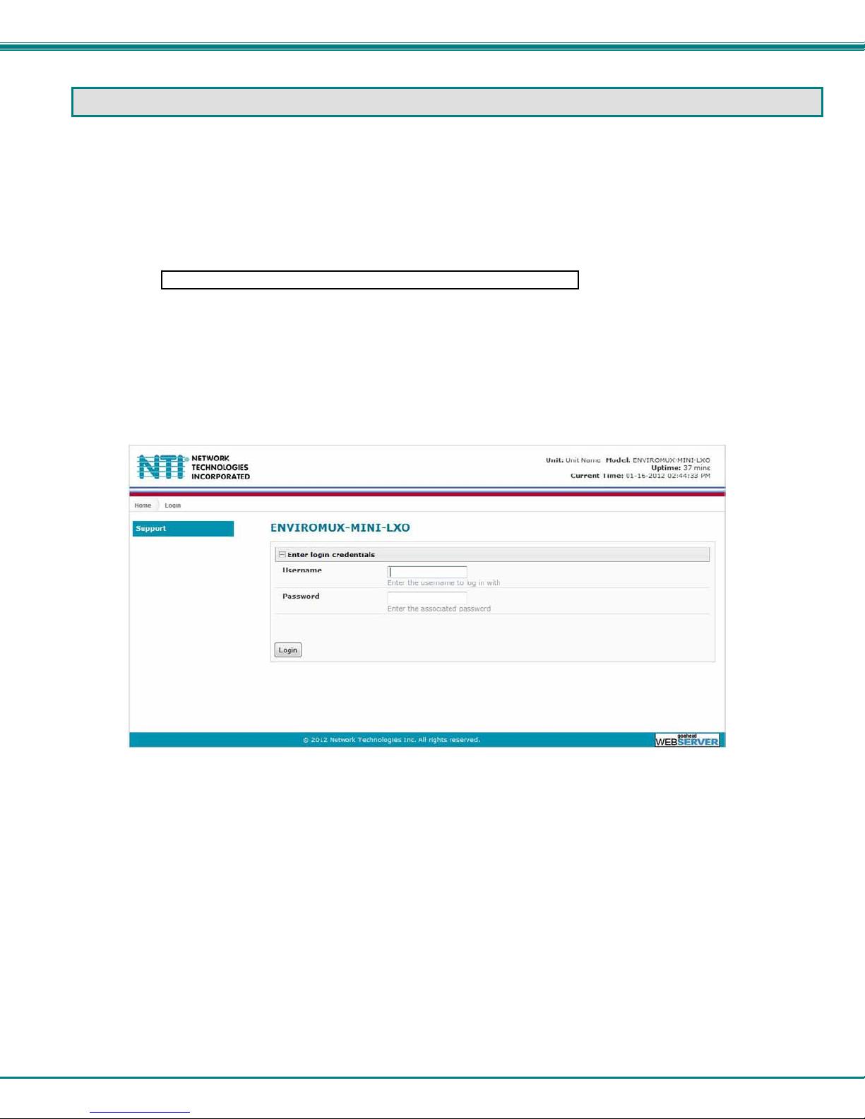
OPERATION VIA WEB INTERFACE
A user may monitor and configure the settings of the ENVIROMUX and any sensor connected to it using the Web Interface via
any web browser (see page 2 for supported web browsers). To access the Web Interface, connect the ENVIROMUX to the
Ethernet (page 6). Use the Device Discovery Tool (page 17) to setup the network settings. Then, to access the web interface
controls, the user must log in.
Log In and Enter Password
To access the web interface, type the current IP address into the address bar of the web browser. (The default IP address is
shown below):
Note: If “Allow HTTP Access” (page 36) is not checked to be enabled (disabled by default) , only an SSL-encrypted
connection will be possible. The software will automatically redirect to an HTTPS (secure) connection. The user will
likely see a warning about the SSL certificate and a prompt to accept th e certificate. The ENVIROMUX uses a selfsigned NTI certificate. Accept the NTI certificate.
A log in prompt requiring a username and password will appear:
http://192.168.1.23
Figure 14- Login prompt to access web interface
Username = root
Password = nti
(lower case letters only)
Note: usernames and passwords are case sensitive
18
Page 26
NTI Mini Server Environment Monitoring System
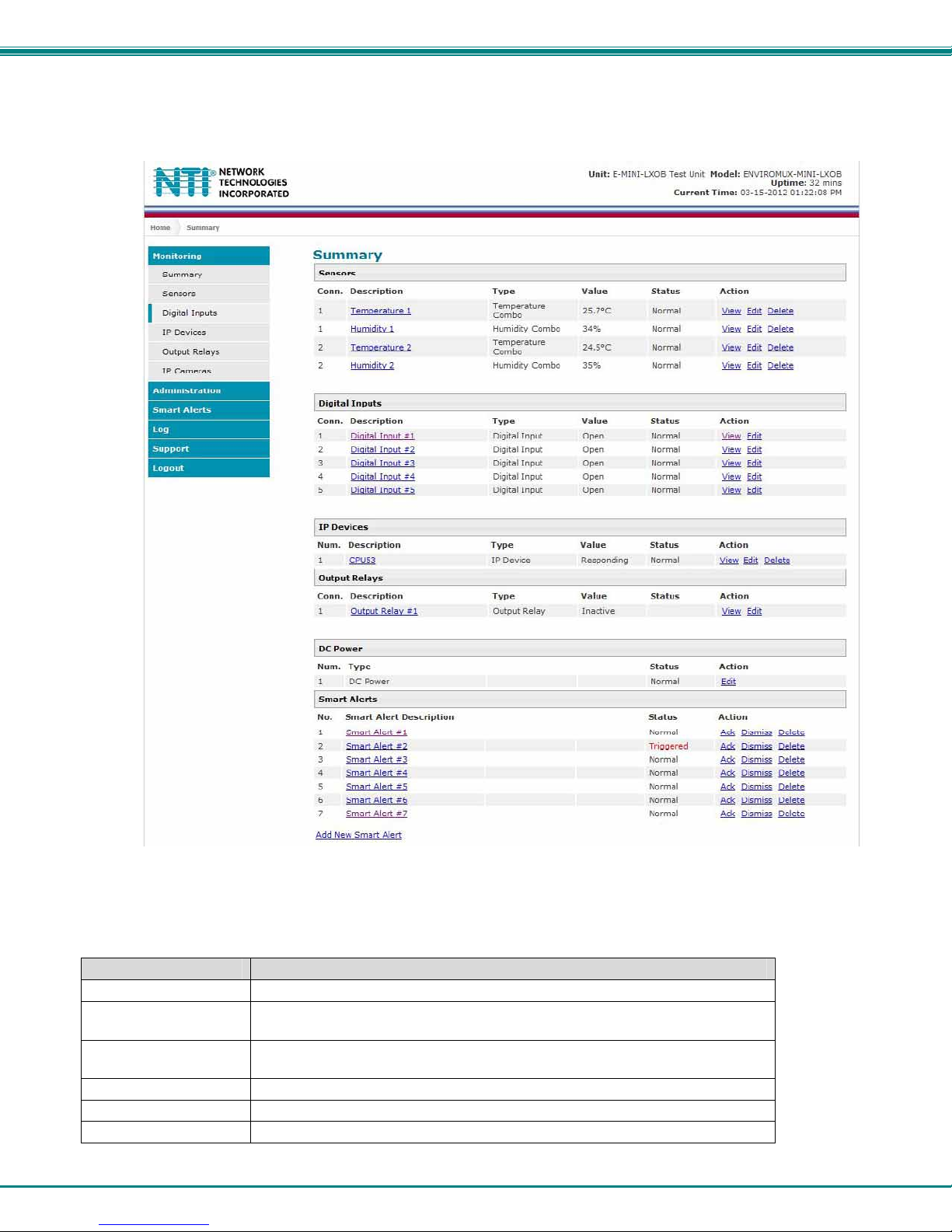
With a successful log in, the “Summary” page with a menu at left will appear on the screen:
Figure 15- Summary page
From this initial page, the user can use the menu to the left to manage all the functions of the ENVIROMUX.
Function Description
MONITORING Monitor the sensors, accessories, and IP devices of the ENVIROMUX (next page)
ADMINISTRATION Configure all system, network, multi-user access, and security settings as
well as upgrade firmware (page 33)
SMART ALERTS View and configure the Events used for Smart Alerts and the Smart Alerts
themselves (page 48)
LOG View and configure the Event and Data Logs (page 55)
SUPPORT Links for downloading a manual, the MIB file, or firmware upgrades
LOGOUT Log the user out of the ENVIROMUX web interface
19
Page 27
NTI Mini Server Environment Monitoring System
Monitoring
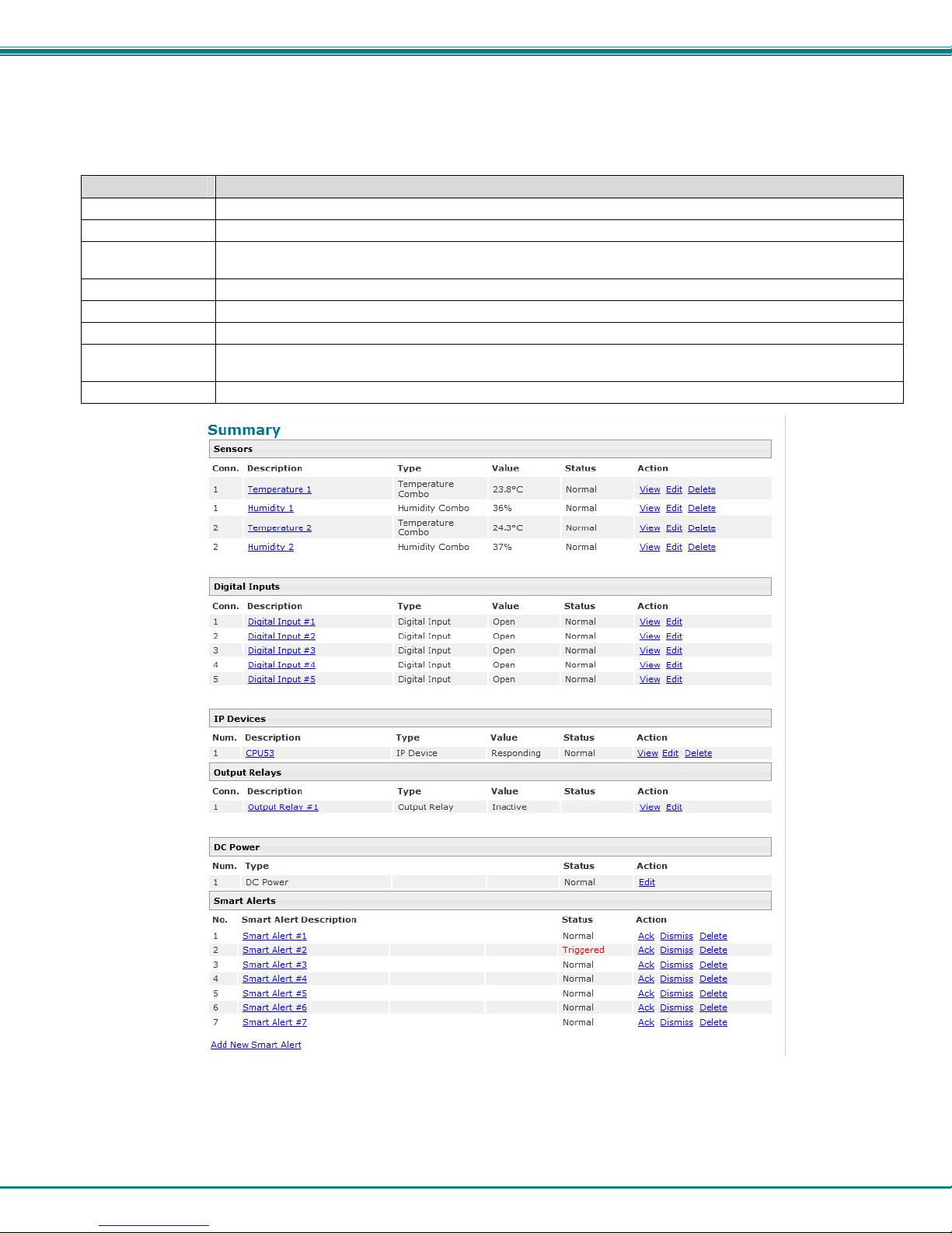
Under Monitoring, there are links to view the status of all sensors and IP Devices being monitored by the ENVIROMUX.
Link Description
Summary Lists all items being monitored, including their description, type, value, and status
Sensors Provides a link to view the status of only the Sensors and a link to add them (page 22)
Digital Inputs Provides a link to view the status of any sensors connected to the CONTACT terminals (1-5) a link to view or
edit their configuration (page 22)
IP Devices Provides a link to view the status of only the IP Devices and a link to add them (page 27)
Output Relay Provides a link to view the status of the output relay and a link to edit the configuration (page 29)
IP Cameras Displays an image from up to 8 webcams with links to connect to each (page 31)
DC Power Provides status of the external DC power supply (page 32) (only applicable on models with battery-backup
feature)
Smart Alerts Displays the status of each Smart Alert configuration (page 48) and provided link to respond when triggered
Figure 16- Summary page and the Monitoring menu
From the Summary page, the user can view the status of all sensors and the IP Devices being monitored by the ENVIROMUX.
Each item listed has a link that when selected will open the status page for that item.
20
Page 28
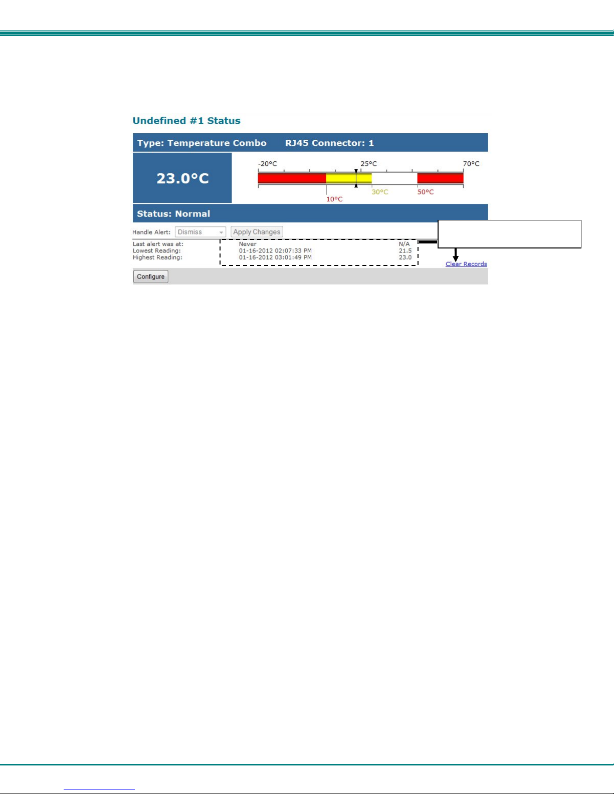
NTI Mini Server Environment Monitoring System
To clear these values and start
over, press “Clear Records”
Figure 17- Status page for a temperature sensor
If the temperature sensor is in alert status, the user has the option to either acknowledge the alert or dismiss it. If the user
acknowledges the alert, no additional alert messages will be sent during that alert status cycle. If the user dismisses the alert,
another alert message will be sent once the “notify again after” time designated on the configuration page (pag e 23) elapses.
After selecting acknowledge or dismiss, click Apply Changes.
The administrative user can open the sensor configuration page by clickin g on the Configure button at the bottom of the sens or
status page (above) or by clicking on Edit from the Summary page. From the sensor configuration page the user can apply
settings to control how or if alert messages are sent in the event the sensor is in alert status, threshold settings, and data logging
settings.
21
Page 29
NTI Mini Server Environment Monitoring System
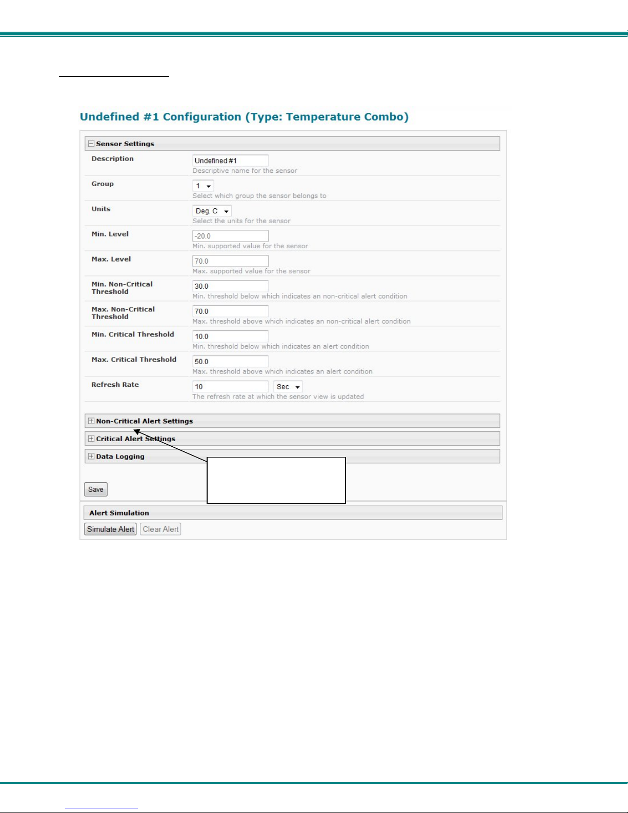
Configure Sensors
The Sensor Configuration page is broken into three sections; Sensor Settings, Alert Settings and Data Logging. To expl ode the
window to see settings for a section, click on the section heading (Figure 18).
Click on section heading to
explode the menu to see
more settings
Figure 18- Sensor Configuration page
Threshold Settings
A sensor designed for connection to the RJ45 ports often has a range of reporting values (for example ENVIROMUX-T has a
range of 32°-104°F). Two levels of threshold values for each end of that range can be configured (above) to initiate two different
alert messages, depending upon the severity of the alert. These levels are identified as “Non-critical” an d “Critical”. Use these
variations in alert communication as needed to inform users of the severity of sensor reading changes. Each level of alert has its
own configuration for how or if the user will be alerted as to a sensor’s status (see Figure 19).
22
Page 30
NTI Mini Server Environment Monitoring System
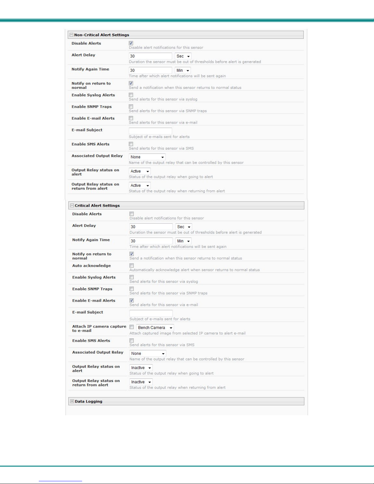
Figure 19- Sensor Configuration- exploded view of additional settings
23
Page 31

NTI Mini Server Environment Monitoring System
Sensor Settings Description
Description The description of the sensor that will be viewed in the Summary page and in the body of alert
messages
Group Assign the sensor to any group 1 -8 (see also page 39)
Units This lets the operator choose between Celsius and Fahrenheit as the temperature
measurement unit.
Min. Level Displays the minimum value that this sensor will report
Max. Level Displays the maximum value that this sensor will report
Minimum Non-Critical -
Threshold
Maximum Non-Critical
Threshold
Minimum Critical Threshold The user must define the lowest acceptable value for the sensors. If the sensor measures a
Maximum Critical Threshold The user must define the highest acceptable value for the sensors. If the sensor measures a
Refresh Rate Determines how often the displayed sensor value is refreshed on the Sensor page. A numeric
Alert Settings (Applies to Critical and Non-Critical Alerts except where noted)
Disable Alerts Place a checkmark in the box to prevent alerts from being sent when this sensor’s status
Alert Delay The alert delay is an amount of time the sensor must be in an alert condition before an alert is
Notify Again Time Enter the amount of time in seconds, minutes, or hours (1-999) before an alert message will be
Notify on Return to Normal The user can also be notified when the sensor readings have returned to the normal range by
Auto Acknowledge Place a checkmark in this box to have alert notifications in the summary page return to normal
Enable Syslog Alerts Place a checkmark in this box to have alert notifications sent via Syslog messages
Enable SNMP traps Place a checkmark in this box to have alert notifications sent via SNMP traps (v2c)
Enable Email Alerts Place a checkmark in this box to have alert notifications sent via Email
Email Subject Enter the subject to be viewed when an ema il alert message is received
The user must define the lowest acceptable value for the sensors. If the sensor measures a
value below this threshold, the sensor will move to non-critical alert status. The assigned value
should be
If values out of the range are entered, and error message will be shown.
The user must define the highest acceptable value for the sensors. If the sensor measures a
value above this threshold, the sensor will move to non-critical alert status. The assigned value
should be
If values out of the range are entered, and error message will be shown.
value below this threshold, the sensor will move to alert status. The assigned value should be
If values out of the range are entered, and error message will be shown.
value above this threshold, the sensor will move to alert status. The assigned value should be
If values out of the range are entered, and error message will be shown.
value and a measurement unit (minimum 1 seconds, maximum 999 minutes) should be entered.
changes
sent. This provides some protection against false alarms. The Alert Delay value can be set
for 0-999 seconds or minutes.
repeated
selecting the "Notify when return to normal" box for a sensor.
state automatically when sensor readings return to normal.
Note: The Non-Critical alert settings do not have this option. Instead, non-critical alert
notifications are always auto-acknowledged when sensor readings return to normal
¾ within the range defined by Minimum Level and Maximum Level and
¾ lower than the assigned Maximum Threshold valu e.
¾ within the range defined by Minimum Level and Maximum Level and
¾ higher than the assigned Minimum Threshold value.
¾ within the range defined by Minimum Level and Maxim um L evel,
¾ lower than the assigned Maximum Threshold value, and
¾ lower than the Minimum Non-Critical Threshold value.
¾ within the range defined by Minimum Level and Maxim um L evel,
¾ higher than the assigned Minimum Threshold value, and
¾ higher than the Maximum Non-Critical Thresh old value.
24
Page 32

NTI Mini Server Environment Monitoring System
g
U
T
Alert Settings (Applies to Critical and Non-Critical Alerts except where noted)
Attach IP Camera capture to
email
Enable SMS Alerts
Associated Output Relay Associate the sensor with the operation of the output relay, or not
Output Relay Status on Alert State the output relay will be in when sensor goes to an alert
Output Relay Status on Return
from Alert
Data Logging
Add to data log This is a check-box that lets the user decide if the data sampled should be recorded in the Data
Logging Period Enter the time period between logged measurements
Be sure to press the Save button to save the configuration settings.
Associate a sensor with a IP camera. Select an IP camera from the drop-down box. An image
will be captured and sent with the alert message when an alert is sent via e-mail. IP cameras
that are monitored by the ENVIROMUX (page 31) will be available for this purpose.
Note: To be able to send IP camera captures as e-mail attachments, viewer security (in
your camera’s configuration) needs to be disabled. Consult your IP camera manual to
see if this feature is present and for instructions on how to do this.
Place a checkmark in this box to have alert notifications sent via SMS messages (requires a
modem)
Note: Only one sensor should be associated with the Output Relay at a time.
Contradicting commands from two or more sensors will result in the output relay
responding to the state directed by the last command received.
State the output relay will be in when sensor is no longer in alert
Log.
Note: If the Output Relay is associated with a sensor, and configured to change state when a senso r crosses threshold
into alert, it will change state even if the alerts are disabled.
More about Groups
Groups are used to create a common relationship between sensors, IP devices, etc. and their alert messages. Each item being
monitored is assigned to one group of 8 possible. Users (a maximum number of 16 including the root user) can receive alert
messages from items in one or more groups (see user configuration on page 39).
Test Alerts
With all the configuration settings completed, each sensor and how the ENVIROMUX will react to an alert conditio n can be tested.
Press the Simulate Alert button at the bottom of the configuration page to test each of the notification methods configured. To
cancel the simulation, press the Clear button.
Note: A simulated alert will test all settings including any delay that has been configured (i.e. if a 2 minute delay is
configured, it will delay sending the email for 2 minutes)
To perform a test, the ENVIROMUX must be properly setup for a user to receive alert messages. Use the chart below to make
sure the ENVIROMUX is setup properly.
Apply a valid e-mail address for the
ENVIROMUX to the Enterprise Setup Page
(see page 36)
Fill in Network Page with valid information
(see page 37)
Create a user profile- be sure to include
valid user e-mail address and assign at
least one group to user to receive
messa
es from (page 40)
Configure sensor and assign sensor to a
group. For a user to receive messages
from this sensor, this group must be
selected in the user profile (above).
se the “Simulate Alert” button to test the
sensor configuration. The sensor will send
a message to the assigned group.
he user will receive the message from the
group as configured in the alert notification
methods on the sensor configuration page
(page 25).
Figure 20- Chart to setup alert notification
25
Page 33

NTI Mini Server Environment Monitoring System
Configure Digital Inputs
The configuration page for digital inputs is almost the same as that for temperature and humidity sensors, with a few differences.
Instead of threshold and minimum/maximum levels settings, digital inputs (water sensors and contact sensors) are either ope n
contact or closed contact sensors. Therefore, the field “Normal Status” is provided to select the status of the sensor when it is
not
in an alert state. Select between Open contacts, or Close contacts for the normal status of the sensor. (Water sensors are
open contact when not in alert state.)
Alert settings and data logging features are the same as those described on page 24.
Select between “Open” or “Closed”
Figure 21- Sensor Configuration for Digital Inputs
26
Page 34

NTI Mini Server Environment Monitoring System
Monitor IP Devices
IP devices such as servers, routers, cameras, etc. can be monitored to make sure network connections are open to them. In
order to monitor an IP Device the devices must be added to the list of IP Devices being monitored. From the Monitoring section
of the menu, click on IP Devices. A page listing IP Devices being monitored will open, with a link to add IP Devices. Click on
Add New IP Device.
Figure 22- IP Devices listing-none monitored yet
The page shown below will open. Enter a description for the new IP Device and the IP Address of the device.
Figure 23- Add New IP Device page
With the address entered in the block, click on the “Add” button.
27
Page 35

NTI Mini Server Environment Monitoring System
The IP Device Configuration page will immediately open. Here you can configure the ENVIROMUX to pin g the IP Device as often
as desired and to react to a lack of response by sending alert messages.
Figure 24- IP Device Configuration page
IP Device Settings Description
Description The description of the IP Device that will be viewed in the Summary page and in the body of alert
messages
IP Address The IP address of the IP Device
Group Assign the IP Device to any group 1 -8
Ping Period Enter the frequency in minutes or seconds that the ENVIROMUX should ping the IP Device
Timeout Enter the length of time in seconds to wait for a response to a ping before considering the attempt a
failure
Retries Enter the number of times the ENVIROMUX should ping a non-responsive IP device before changing
its status from normal to alarm and sending an alert
The alert settings and data logging are the same as for sensor configuration, described on page 24.
28
Page 36

NTI Mini Server Environment Monitoring System
With a couple of IP devices having been configured for monitoring, the IP Device list will provide links to them for viewing their
status, editing their configuration, or deleting them from the list.
Figure 25- IP Device list with new devices added
To view the graphic image showing the status of an IP address, click on the IP Device description or click View. From the IP
Device status page, the user can view the current status, either dismiss or acknowledge an alert, or open the IP Device
configuration page (if the user has administrative privileges). If you have found the device to be in an alert state and have either
dismissed or acknowledged it, be sure to click the Apply Changes button.
Figure 26- IP Device Status page
Monitor Output Relay
An output relay is provided to control an external device with a rating of up to 1A, 30VDC or 0.5A, 125VAC. The relay state is
monitored to be either inactive (relay is at rest; contacts as indicated by product markings) or active (relay is energized; contacts
are opposite that of product markings). The status of the relay can be changed either manually through the web interface, or as a
result of an alert (page 22).
Figure 27- Output Relay Status
To set the state of the relay manually, from the relay status page (Figure 27), select the arrow next to “Set Output” to drop down
the window and select either “Deactivate” or “Activate”. Then click the “Apply Changes” button.
29
Page 37

NTI Mini Server Environment Monitoring System
N
ote: A recent design improvement
resulted in a change to the pinout of
the output relay in the ENVIROMUXMINI-LXO. Please be aware of the
change and note which version yours
is. The previous version is shown
below.
Figure 28- Output Relay Contact State
To change settings for the output relay and whether or not a state change should generate an alert message, click the “Confi gure”
button.
Figure 29- Configure Output Relay
From the configuration page, the user can apply a description of the relay that will be used on the summary page and in any alert
messages sent, if so configured.
To have messages sent to specific members, select the monitoring group the relay will belong to.
Choose the Normal Status for the relay, between Inactive or Active. When the status changes from what is defined as “normal”,
an alert will be sent if so configured.
When the relay is an alert state, the ENVIROMUX can be configured to send an email, syslog and SMS alerts, as well as an
SNMP trap to the users subscribing to alerts in the selected group. Place a checkmark in the box for those features you wish
to enable.
If email alerts is enabled, enter an e-mail subject line that will get the attention of the recipient(s).
30
Page 38

NTI Mini Server Environment Monitoring System
Monitor IP Cameras
The IP Cameras page displays the video
snapshots of up to 8 monitored IP cameras.
ENVIROMUX will display the video from
specified IP addresses and provide images at
320 x 240 resolution. To configure the IP
cameras to be monitored, click on the
“Configure IP Cameras” link.
Click to configure
Figure 30- IP Camera Monitoring
Place a name, the URL or IP address of the link, and the
full path including name of the image taken by the
camera in the blocks provided, click the "Add to view"
checkbox, and click SAVE at the bottom of the page.
Then click on Monitoring->IP Cameras to see the
images taken by those cameras. The images can be
set to be refreshed every 100 msec (.1 second) up to
99,900 msec (almost 100 seconds). The user can click
on any image and be connected to the site defined by
the URL or IP Address.
Figure 31- Configure IP Cameras
The images from IP cameras can also be associated with alert messages. When configured (page 22), an image from a IP
camera can be taken and sent along with a sensor alert message via email.
Note: To be able to send IP camera captures as e-mail attachments, viewer security (in your camera’s configuratio n)
needs to be disabled. Consult your IP camera manual to see if this feature is present and for in structions on how to do
this.
31
Page 39

NTI Mini Server Environment Monitoring System
DC Power
On the Summary Page (under Monitoring), the status of the DC power supply can be found (only applicable for models with
battery backup). The ENVIROMUX will monitor the power coming into the ENVIROMUX and can be configured to send an alert
in the event that power supply fails. Click on “Edit” to configure how the ENVIROMUX should respond.
Figure 32- Excerpt from the Summary Page showing DC Power monitoring
Figure 33- DC Power Alert Configuration
Many of the same options that apply to sensor alerts (page 22) can be configured for DC Power alerts. The battery backup will
keep the ENVIROMUX on line for up to 2.3 hours in the event of a power failure.
32
Page 40

NTI Mini Server Environment Monitoring System
Administration
From the Administration section there are several sub sections for configuring the ENVIROMUX:
System Fields for applying time zone, date, time, NTP server, and backup and restore
configuration settings
Enterprise Fields for assigning the unit name, address, contact person, the ENVIROMUX e-
mail address, and phone number of a contact person
Network Fields for providing all the network settings the ENVIROMUX including IP
address, DNS, SMTP and SNMP settings
Users Fields for assigning users, access privileges, passwords, contact settings, and
schedule settings
Security Fields for setting authentication method and IP Filtering
System
Information
Firmware For updating the firmware of the ENVIROMUX when improved software
Reboot Enables user to reboot the ENVIROMUX using the web interface
System Configuration
The System Configuration section is where all the settings necessary for proper time reporting within alert messages and log
records are configured. To view the System Configuration page, click on System from the Administration section of the menu.
For viewing ENVIROMUX system information
becomes available.
Figure 34- System Configuration page
33
Page 41

NTI Mini Server Environment Monitoring System
The Date and Time of the ENVIROMUX can be either manually setup to use an onboard clock or set to be synchroniz ed with an
NTP server. The configuration of the ENVIROMUX can also be easily backed up to a file on your PC and restored from that file
as needed.
Time Settings Description
Time Zone Enter the appropriate time zone
Enable Daylight Saving Apply a checkmark to have the time change according to Daylight Saving Time rules
Set Date Enter the system date in MM-DD-YYYY format
Set Time Enter the system time of day in hh:mm:ss format
Enable NTP Place a checkmark to enable the ENVIROMUX to automatically sync up with a time server via
NTP
NTP server If the NTP is enabled, enter the Domain Name or IP address of the NTP server
NTP Frequency Enter the frequency (in minutes) for the ENVIROMUX to query the NTP server (minimum is 5
minutes)
E-mail Time Stamp Place a checkmark to have the ENVIROMUX apply a time of day stamp in the alert message
sent via email
SMS Time Stamp Place a checkmark to have the ENVIROMUX apply a time of day stamp in the alert message
sent via SMS
Configuration Backup &
Restore
Choose file Browse for a saved configuration file to be restored to the ENVIROMUX. Upon selection, the
ENVIROMUX will restore the configuration settings and reboot. Allow 1 minute before trying to
reconnect and log in again.
Note: The IP address will be set to the IP address in the file and may be different
Download Configuration File Click this button to save the configuration of the ENVIROMUX to a location on your PC. This
file can be restored using the “Choose file” field in the event you wish to return the
ENVIROMUX to a former state
Restore Defaults Click this button to restore the ENVIROMUX to the configuration settings it had upon receipt
from the factory. Be careful! This will erase all
user configuration settings. Upon
restoration, the ENVIROMUX will reboot. Allow 1 minute before trying to reconnect and log in
again.
Confirmation is required.
Note: If “Restore Defaults” is used, the IP address will also be restored to its default address of 192.168.1.23 with a login
name “root” and password “nti”. To restore the root password to “nti” without having to restore all default settings,
contact NTI for assistance.
To identify the IP address of the ENVIROMUX without restoring defaults, use the Discovery Tool (page 17).
Click on Save when finished with Time Setting changes.
Default settings can also be restored using the “Restore Defaults” button on the front of the ENVIROMUX (page 101) or through
the serial interface via text menu (page 78)
34
Page 42

NTI Mini Server Environment Monitoring System
Enterprise Configuration
The Enterprise Configuration page is used to enter basic company information to be applied to the body of alerts. To view the
Enterprise Configuration, click on Enterprise from the Administration section of the menu. Enter in the blocks your unit name,
location, the contact person that alert e-mails should refer to, the phone number to reach them, and the e-mail address assigned
to the ENVIROMUX.
If a GSM modem is properly installed (page 14), the “Modem Status” found in the GSM Modem Status section will indicate
“Connected” and the IMEI number for the modem will be indicated. Once the modem makes connection with the cell tower,
“Connected” will change to “Ready” (as seen below).
Note: It may take several minutes for the GSM modem to be detected by the ENVIROMUX.
GSM modem is properly installed
Figure 35- Enterprise Configuration- Modem Status “Ready”
If no modem is installed, the modem type will be “Not Available” and the status will be “Not Connected”.
Figure 36- No Modem Installed
35
Page 43

NTI Mini Server Environment Monitoring System
Network Configuration
From the Network Setup page the administrator can either choose to have the IP address and DNS infor m ation filled in
automatically by the DHCP server, or manually fill in the fields (use a static address). Settings can be entered for either the IPv4
or IPv6 protocols. To view the Network Configuration page, click on Network from the Administration section of the menu.
Note: If you select “DHCP”, make sure a DHCP server is running on the network the ENVIROMUX is connected to.
Note: The values shown here are
for local (static) address
configuration only.
Address values for DHCP
configuration will only be displayed
in the System Information page
(page 46).
Figure 37- Network Configuration page
IPv4 Settings Description
Mode Select between Static (manual) , or DHCP (automatic IP and DNS) settings
IP Address Enter a valid IP address (default address shown above)
Subnet Mask Enter a valid subnet mask (default value shown above)
Default Gateway Enter a valid gateway (defau lt gateway shown above)
Preferred DNS Enter a preferred domain name server address
Alternate DNS Enter an alternate domain name server address
Enter IPv6 settings as applicable.
For descriptions of SMTP, SNMP, and Server Settings, see page 38. .
36
Page 44

NTI Mini Server Environment Monitoring System
The Network Configuration page is broken into four sections; IP Settings, SMTP Settings, SNMP Settings, and Server Settings.
To explode the window to see settings for a section, click on the section heading.
Common Port numbers:
Default: 25 (Not secure)
SSL: 465 (Secure)
TLS: 587 (Secure)
Contact your network
administrator for required
settings.
Figure 38- Network Configuration- more settings
37
Page 45

NTI Mini Server Environment Monitoring System
More Network Settings (see Figure 38)
SMTP Settings Description
SMTP Server Enter a valid SMTP server name (e.g. yourcompany.com)
Port Enter a valid port number (default port is 25, for SSL most use 465, for STARTTLS most use
587)
Use SSL Place a checkmark in the box if the SMTP server supports SSL
Use STARTLS Place a checkmark in the bo x if the SMTP server supports TLS
Use Authentication Place a checkmark in the box if the SMTP server requires authentication to send email
Username Enter a valid username to be used by the ENVIROMUX to send emails
Password Enter a valid password assigned to the ENVIROMUX username
SNMP Settings
Enable SNMP agent Place a checkmark in the box to enable access to the SNMP agent
Enable SNMP traps Place a checkmark in the box to allow SNMP traps to be sent
Read-write community name
Read-only community name Enter applicable name (commonly used- “public”)
Server Settings
Enable Telnet Place a checkmark in the box to enable access to the ENVIROMUX via Telnet
Enable SSH Place a checkmark in the box to enable access to the ENVIROMUX via SSH
Enabe HTTP access Place a checkmark in the box to enable access to the ENVIROMUX via standard (non-secure)
HTTP Port Port to be used for standard HTTP requests
HTTPS Port Port to be used for HTTPS requests
Web Timeout Number of minutes after which idle web uses will be logged-out (enter 0 to disable this feature)
If the administrator chooses to have the IP and DNS information filled in automatically via DHCP, the SMTP server and port
number still need to be entered for email alerts to work. If the SMTP server requires a password in order for users to send emails,
the network administrator must first assign a user name and password to the ENVIROMUX.
Enter applicable name (commonly used- “private”) Not applicable as of this printing
The default is disabled.
HTTP requests
Note: The SMTP server port number is shown in Figure 38 as "25". This is a common port number assigned, but not
necessarily the port number assigned to your SMTP server. For SMTP servers that support SSL, the common port
number is 465, and for those that support TLS, the common port number is 587.
The administrator may assign a different HTTP Server Port than is used by most servers (80).
Note: If the port number is changed and forgotten, to determine what it has been changed to connect the ENVIROMUX
for control using the text menu (page 59) and review the Miscellaneous Servic e Settings (page 82).
Read-Only Community Name
The SNMP Read-only community name enables a user to retrieve "read-only" information from the ENVIROMUX using the SNMP
browser and MIB file. This name must be present in the ENVIROMUX and in the proper field in the SNMP browser.
Read-Write Community Name
(not applicable as of this printing)
The SNMP Read-Write community name enables a user to read information from the ENVIROMUX and to modify settings on the
ENVIROMUX using the SNMP browser and MIB file. This name must be present in the ENVIROMUX and in the proper field in
the SNMP browser.
38
Page 46

NTI Mini Server Environment Monitoring System
User Configuration
The Users page is a list of all configured users of the ENVIROMUX. A maximum of 15 users (other than root) can be configured.
From this page the user can choose to add more users, go to the user configuration page to edit a user’s access to the
ENVIROMUX, or delete a user from the list. To view the Users page, click on Users from the Administration section of the
menu.
Figure 39- Users page
To add a user, click on the “Add New User” link.
To edit a user’s configuration, either click on the listed username, or on the “Edit” link.
To delete a user and their configuration, click on “Delete” link.
When adding a new user, the Configure User page will open with the username “userx” assigned, where x = the next
consecutive number (up to 15) based on the quantity of users in the list (other than the root user). You can either leave the
name as “userx”, or change it to what you would like to see listed. With the name assigned, fill in the remaining information as
needed.
Figure 40- Configure Users page
39
Page 47

NTI Mini Server Environment Monitoring System
Figure 41- Configure User- more options
40
Page 48

NTI Mini Server Environment Monitoring System
Account Settings Description
Username Enter the desired username for this user
Admin Place a checkmark here if this user should have administrative privileges
Enabled Place a checkmark here to enable this user to access the ENVIROMUX
Password Enter a password that a user must use to login to the system
A password must be assigned for the user’s login to be valid
Passwords must be at least 1 keyboard character.
Confirm Re-enter a password that a user must use to login to the system
Title Enter information as applicable
Department Enter information as applicable
Company Enter information as applicable
Group Settings
Group 1-8 Place a checkmark if the user should receive messages from sensors, accessories, or IP
Contact Settings
Email alerts Place a checkmark if the user should receive messages via email
Email address Enter a valid email address if this user should receive email alert messages
Syslog alerts Place a checkmark if the use r should receive alerts via syslog messages
SNMP traps Place a checkmark if the user should receive alerts via SNMP traps
Syslog/SNMP IP address Enter a valid syslog/SNMP IP address for the user to receive syslog/SNMP messages
SMS Alerts Place a checkmark if the user should receive alerts via SMS messages
SMS Number Enter a phone number for the GSM modem to call to alert the user via SMS message
Schedule Settings
Schedule Type
Start Day First day of the week the user should begin receiving messages
End Day Last day of the week the user should receive messages
Start Hour First hour of the day the user should begin receiving messages
End Hour Last hour of the day the user should receive messages
SNMP Settings
Authentication Protocol Choose between MD5 or SHA to require authentication, or none to disable it
Authentication Passphrase Assign the passphrase to be used to enable the receipt of SNMP v3 messages
Privacy Protocol
Privacy Passphrase
Traps Type Choose between SNMPv1, SNMPv2C, or SNMPv3
After changing any settings in the user profile, press “Apply”.
devices in Group 1, 2, 3… thru 8 (see also pages 24 and 28 for group assignments)
Always active- user will receive messages at all hours of each day
Active during defined times- user will only receive alert messages during times as
outlined below
Choose between DES or AES to encrypt SNMP readings or traps or none to disable encryption.
If encryption is enabled, then the Authentication Protocol must also be set at “MD5” or “SHA”.
Assign the passphrase to be used to open and read readings or alert messages received via
SNMP v3
41
Page 49

NTI Mini Server Environment Monitoring System
More about User Privileges
The root user (or any user with administrator rights) can change the root password and configure how the root user will receive
alert messages. Users with administrative rights can change all configuration settings except for the root user name.
Users with user rights can only see the current readings of monitored items and change their o wn passwords.
Figure 42-Summary page for User without Admin privileges
42
Page 50

NTI Mini Server Environment Monitoring System
Security
Security in the ENVIROMUX can be managed one of two ways; through the local settings (passwords assigned in user settings on
page 41) or through an LDAP server. If security is configured to use LDAP mode, then the passwords for users must be those
found on a configured LDAP server. To view the Security Configuration page, select Security in the Administration section of
the menu.
Figure 43- Security Configuration page
When in LDAP mode, usernames on the LDAP server must match those in the user settings of the ENVIROMUX or access will be
denied.
Note: When in LDAP mode, if the LDAP server is not responding, local authentication will be tried.
User Authentication
Mode Select Local to use authentication based on passwords in the ENVIROMUX user configuration
Select LDAP to use authentication based on passwords in an LDAP server
LDAP Primary Server Enter Hostname or IP address of Primary LDAP Server
LDAP Secondary Server Enter Hostname or IP address of Secondary LDAP Server (optional)
LDAP Server Type Choose from drop down list:
Generic LDAP server
Novell Directory server
Microsoft Active Directory
LDAP User Base DN Enter the Base DN for users (ex: ou=People,dc=mycompany,dc=com)
Even though LDAP authentication is being used, each user must also have a local account. User permission level is established
by the local account.
43
Page 51

NTI Mini Server Environment Monitoring System
Included in the Security Configuration options is IP Filtering. IP Filtering provides an additional mechanism for securing the
ENVIROMUX. Access to the ENVIROMUX network services (SNMP, HTTP(S), SSH, Telnet) can be controlled by allowing or
disallowing connections from various IP addresses, subnets, or networks.
Up to 16 IP Filtering rules can be defined to protect the ENVIROMUX from unwanted access from intruders. Each rule can be set
as Enabled or Disabled. Rules can be set to explicitly drop attempts to connect, or to accept them.
Be sure to press Save after changes are made.
Figure 44- Security Configuration- IP Filtering Rules
44
Page 52

NTI Mini Server Environment Monitoring System
More on IP Filtering
The most common approach is to only allow “white-listed” IP addresses, subnets, or networks to access the device while blocking
all others. The IP Filters are processed sequentially from top to bottom, so it is important to place the most precise rules at the top
of the list and the most generic rules at the bottom of the list.
As an example, assume we wish to block all connections except those which come from the IP address 192.168.1.100. To allow
connections from 192.168.1.100, we need to configure and enable an ACCEPT rule at the top of the list:
Then, to block all other IP addresses from connecting to the ENVIROMUX, we add a rule to drop all other connections.
If the preceding “drop all connections” rule was placed in position one, no connections at all would be allowed to the unit.
Remember: rules are processed from top to bottom. As soon as a rule matches, the processing stops and the matching rule is
executed.
To match a particular IP address, simply enter in the desired IP address (e.g. 192.168.1.100).
To match a subnet, enter in the subnet with the associated mask (e.g. 192.168.1.0/24).
To match all IP address, specify a mask of 0 (e.g. 0.0.0.0/0).
System Information
The system information page displays the model name of the ENVIROMUX, the firmware version in the ENVIROMUX, the MAC
address of the Ethernet port, the IP mode, and the network configuration. To view the System Information, select System
Information in the Administration section of the main menu.
Figure 45- System Information page
45
Page 53

NTI Mini Server Environment Monitoring System
Update Firmware
The Update Firmware page is used to change the firmware of the ENVIROMUX. Occasionally new features or changes to
existing features will be introduced and new firmware with these changes will be made available on the NTI website
(http://www.networktechinc.com/download/d-environment-monitoring.html
Firmware in the Administration section of the main menu. Once a user has downloaded the required file for firmware upgrade,
this page will be used to upload it to the ENVIROMUX.
). To view the Update Firmware page, select
Figure 46- Update Firmware page
1. Download the most current firmware file from http://www.networktechinc.com/download/d-environment-monitoring.html
to a location on your PC.
2. Click on the “Browse” button and locate and select the firmware file for the ENVIROMUX (enviromux-mini-lxo-vx-
x.bin, for example).
3. Click on the “Update” button to perform the firmware update. The firmware update process will take approximately 5 minutes
while the ENVIROMUX installs the firmware. Once the update file has been installed, the unit will automatically
reboot and the login screen will appear.
46
Page 54

NTI Mini Server Environment Monitoring System
Reboot the System
The ENVIROMUX can be remotely rebooted by anyone with administrative privileges. To view the Reboot System page, select
Reboot in the Administration section of the main menu. Click the Reboot Now button to cause the ENVIROMUX to reboot.
This will disconnect any user and shut down all activity.
Figure 47- Reboot System page
The message “System is rebooting, please wait..... “ will appear and after approximately 45 seconds the login screen will appear.
Log in to resume activity.
Figure 48- System is rebooting
47
Page 55

NTI Mini Server Environment Monitoring System
Smart Alerts
Smart Alerts enable the ENVIROMUX to contact users when specially configured circumstances exist for defined sensors. Smart
Alerts will respond to 1 or more alert conditions independent of the alert configurations for each sensor configured on page 22.
Assorted conditions can produce configurable events that can then be used in numerous scenarios to produce Smart Alert
messages that are sent to users.
To begin, Events must be defined and configured. Events are sensor conditions to be notified of. Events logged based on the
sensor configurations described on page 22 will be managed separately from events lo gged by these pre-defined Events. Sensor
configuration for these Events will have no impact on the general configuration of your sensors. Pre-defined Events provide more
control over what you want to be notified of.
Figure 49- Events used for Smart Alerts
From the side menu, select “Smart Alerts”, and “Events”. On the Events page, click on “Create New Event”.
Figure 50- Sensor to be used for a predefined event
You will be prompted to select which connected sensor to associate the event with. Which sensor’s data do you want to trigger
this event? Once selected, click “Add”.
48
Page 56

NTI Mini Server Environment Monitoring System
Figure 51- Configuration options for new event
Depending upon the type of sensor chosen, various event settings can be configured that will cause an event to be l ogged.
In the example above, if the temperature sensor sees a temperature greater than 75.0 degrees C for more than 30 seconds, and
event will be logged.
Event Notifications can then be configured to be sent, with the options described in the following table.
Event Settings
Description The description of the sensor that will be viewed in the Summary page and in the body of alert
messages
Threshold (for RJ45 sensors) The threshold value of the measured unit that will trigger an event
Note: The trigger value can be a value that is considered a sensor’s “normal” state, or its
“alert” state.
Threshold Type The type of variation from the threshold value that indicates a condition (greater than or less
than)
Trigger Status (for digital
inputs)
Event Delay The amount of time the event must be triggered before an event is logged. This provides some
When triggered, acknowledge
the following event
Event Notification Settings
Group Assign the Event to any group 1 -8 (see also page 39)
Notify Again Time Enter the amount of time in seconds, minutes, or hours (1-999) before an alert message will be
Notify on Return to Normal The user can also be notified when the Event has returned to a non-triggered state by selecting
The condition of the sensor that indicates a triggered state (open or closed)
protection against false alarms. The Event Delay value can be set for 0-999 seconds or
minutes.
Selecting an event for this field gives the option to cancel notice of another separate event
(acknowledge) when current event is triggered
repeated
the "Notify when return to normal" box for an Event.
49
Page 57

NTI Mini Server Environment Monitoring System
Event Notification Settings (Continued)
Auto Acknowledge Place a checkmark in this box to have alert notifications in the summary page return to normal
state automatically when an Event is no longer being triggered.
Enable Syslog Alerts Place a checkmark in this box to have alert notifications sent via Syslog messages
Enable SNMP traps Place a checkmark in this box to have alert notifications sent via SNMP traps (v2c)
Enable Email Alerts Place a checkmark in this box to have alert notifications sent via Email
Email Subject Enter the subject to be viewed when an ema il alert message is received
Attach IP Camera capture to
email
Enable SMS Alerts
After all options are selected, click the “Save” button. This Event will now be added to the Events page (Figure 49). Up to 50
events can be defined. Events can be configured to trigger alerts by themselves, and/or be used in combination with other
events to trigger Smart Alerts.
With Events defined, Smart Alerts (up to 20) can be configured to use Event combinations to send alert messages.
Associate an Event with an IP camera. Select an IP camera from the drop-down box. An
image will be captured and sent with the alert message when an alert is sent via e-mail. IP
cameras that are monitored by the ENVIROMUX (page 31) will be available for this purpose.
Note: To be able to send IP camera captures as e-mail attachments, viewer security (in
your camera’s configuration) needs to be disabled. Consult your IP camera manual to
see if this feature is present and for instructions on how to do this.
Place a checkmark in this box to have alert notifications sent via SMS messages (requires a
modem)
Figure 52- Smart Alert summary page
From the side menu, select “Smart Alerts”, and “Smart Alerts” again. On the Smart Alerts page, click on “Add New Smart Alert”.
A new numbered Smart Alert will be added to the summary page (above). To configure the Smart Alert, click on it.
50
Page 58

NTI Mini Server Environment Monitoring System
A menu will open with many options to choose to make the best use of the information provided by the events.
Figure 53- Smart Alert configuration
51
Page 59

NTI Mini Server Environment Monitoring System
DESCRIPTION
Description Use the default description provided or enter the description you want to see on notifications
received.
OR Events
Available Events Select from the predefine d available Events (Figure 49) to have OR logic applied to a triggered
Event
AND Events
Available Events Select from the predefine d available Events (Figure 49) to have AND logic applied to a triggered
Smart Alert Configuration
Logical Function Logical function to be applied to the output of the logical status of the OR and AND lists to
Delay The amount of time the Smart Alert Event status must be in an alert condition before a Smart
Smart Alert Notifications
Group Assign the Smart Alert to any group 1 -8 (see also page 39)
Notify Again Time Enter the amount of time in seconds, minutes, or hours (1-999) before an alert message will be
Notify on Return to Normal The user can also be notified when the Smart Alert conditions have returned to the normal (non-
Auto Acknowledge Place a checkmark in this box to have alert notifications in the summary page return to normal
Enable Syslog Alerts Place a checkmark in this box to have alert notifications sent via Syslog messages
Enable SNMP traps Place a checkmark in this box to have alert notifications sent via SNMP traps (v2c)
Enable Email Alerts Place a checkmark in this box to have alert notifications sent via Email
Email Subject Enter the subject to be viewed when an ema il alert message is received
Attach IP Camera capture to
email
Enable SMS Alerts
Smart Alert Command
Associated Output Relay Associate the Smart Alert with the operation of the output relay, or not
Output Relay Status on Alert State the output relay will be in when a Smart Alert is triggered
Output Relay Status on Return
from Alert
Event
determine when a Smart Alert should be generated.
Options include OR, AND, XOR, NOR and NAND
Alert message is triggered. This provides some protection against false alarms. The Delay
value can be set for 0-999 seconds or minutes.
repeated
triggered state) by selecting the "Notify when return to normal" box.
state automatically when Smart Alert conditions return to normal.
Associate a Smart Alert with an IP camera. Select an IP camera from the drop-down box. An
image will be captured and sent with the alert message when an alert is sent via e-mail. IP
cameras that are monitored by the ENVIROMUX (page 31) will be available for this purpose.
Note: To be able to send IP camera captures as e-mail attachments, viewer security (in
your camera’s configuration) needs to be disabled. Consult your IP camera manual to
see if this feature is present and for instructions on how to do this.
Place a checkmark in this box to have alert notifications sent via SMS messages (requires a
modem)
Note: Only one sensor or Smart Alert should be associated with the Output Relay at a
time. Contradicting commands from two or more sensors or Smart Alerts will result in
the output relay responding to the state directed by the last command received.
State the output relay will be in when a Smart Alert is no longer being triggered
More on Logical Functions
Using Logical Functions, you can select how to use or not use the reported state of an Event. You can combine the information
from multiple Events to achieve an end result.
52
Page 60

NTI Mini Server Environment Monitoring System
Figure 54- Event Logical Function Diagram
Smart Alert Rules:
• Any configured Event can be applied to either the OR Events list or the AND Events list, or both lists.
• Events can be configured to be triggered by a sensor or monitored device in alert state or in normal state.
• Each list will generate an output value, the value to either send a n al ert (1), or not (0).
• If any
• All
The Logical Function combines the two values to determine if a Smart Alert should be sent, as detailed in the table below:
OR
List
Example: If the OR list value is at 0, and AND list value is at 0, when the Logical Function is set to OR a Smart Alert will
NOT be generated.
AND
List
0 0 No 0 0 Yes
1 0 Yes 1 0 No
0 1 Yes 0 1 No
1 1
0 0 No 0 0 Yes
1 0 Yes 1 0 Yes
0 1 Yes 0 1 Yes
1 1
0 0 No
1 0 No
0 1 No
1 1
Event in the OR list is triggered, the output value of the OR list will be 1.
Events in the AND list must be triggered for the output value of the AND list to be 1.
Logical
Function
OR
XOR
AND
Smart Alert
Generated
Yes 1 1
No 1 1
Yes
OR
List
AND
List
Logical
Function
NOR
NAND
Smart Alert
Generated
No
No
53
Page 61

NTI Mini Server Environment Monitoring System
Figure 55- Examples of Smart Alert conditions
54
Page 62

NTI Mini Server Environment Monitoring System
Log
From the Log section there are three sub sections for configuring the ENVIROMUX:
View Event Log
The Event Log provides the administrative user with a listing of many events that occur within the ENVIROMUX. The event
log will record the date and time of:
Select all
View Event Log View a log listing the date and time of events such as startups, shut downs,
user logins
View Data Log View data readings from sensors and IP addresses
Log Settings Configure how the logs are sent to users, how they handle reaching capacity,
which users will be notified that it has reached capacity, and how they will be
notified
• each ENVIROMUX startup,
• each user login and logout time,
• any time an unknown user tries to login,
• sensor and IP device alerts
• an alert handled by a user
Figure 56- Event Log page
From the Event Log page the administrative user can view the logs, select specific logs to be deleted or press Clear Log to delete
them all. The number of entries per page can be changed for the user’s reading preference. Navigating between pages is as
easy as clicking Previous or Next buttons, or jumping to a specific page if you know where the log entry you are interested in is
listed.
To clear only specific log entries, place a checkmark in each line item to be deleted, and press Delete Selected. To select all
entries at once, place a checkmark in the uppermost box. Before deleting, the user may want to save the log for future reference
and to make space for more logs by downloading the event log to a file on a PC. Press Download Event Log to save the log file
before clearing it.
55
Page 63

NTI Mini Server Environment Monitoring System
View Data Log
The Data Log provides the administrative user with a listing of all the readings taken by the ENVIROMUX pertaining to the
sensors and IP Devices being monitored. The event log will record the date and time of each reading.
Select all
Figure 57- Data Log page
From the Data Log page the administrative user can view the logs, select specific logs to be deleted or press Clear Log to delete
them all. The number of entries per page can be changed for the user’s reading preference. Navigating between pages is as
easy as clicking Previous or Next buttons, or jumping to a specific page if you know where the log entry you are interested in is
listed.
To clear only specific log entries, place a checkmark in each line item to be deleted, and press Delete Selected. To select all
entries at once, place a checkmark in the uppermost box. Before deleting, the user may want to save the log for future reference
and to make space for more logs by downloading the event log to a file on a PC. Press Download Data Log to save the log file
before clearing it.
Log Settings
The Log Settings page (Figure 58) provides settings for how the ENVIROMUX will react when its Data and Event logs reach
capacity.
The Event Log settings include a logging level that can be configured to log different amounts of information:
• Error : shows only system errors (like sending e-mail failures or SMS)
• Alerts: shows recorded system errors and alert messages
• Info: In addition to all of the above, the log will show less relevant information: user login/logout for example
Each log can be assigned to a group and any user that receives messages from that group can be notified when capacity is being
reached.
The log can be set to either :
• Discontinue- stop logging information
• Clear and restart- delete all log entries and restart with new entries
• Wrap- continue logging but delete the oldest entries so new ones can be recorded
56
Page 64

NTI Mini Server Environment Monitoring System
The Data and/or Event log can be set to send alerts to users via email, syslog, and/or SNMP traps once it has reached 90% of
capacity, allowing them time to react.
The Data log can also be set to send log entries via email, syslog, or SNMP traps to users in addition to the entries it records
internally. Enable Remote Logging for email, syslog, of SNMP as desired.
Apply a checkmark in this box
to enable the recording of logs
to the flash drive.
Note: Be sure to remove the
checkmark before removing a
flash drive from the
ENVIROMUX.
Otherwise data on the drive
may be lost.
Figure 58- Log Settings page
Log to USB Flash Settings
Event and Data log messages are automatically sent to users as configured above in addition to being recorded in the logs. The
logs can also be downloaded as a tab-delimited plain text file. If a USB flash drive is pres ent, logs will also be recorded on the
flash drive to make them portable provided the feature is enabled.
The number of logs that can be recorded depends on the capacity of the flash drive installed. To begin recording to the flash drive,
place a checkmark in the “Enable Log to Flash drive” box. Be sure to remove the checkmark before removing the flash drive
from the ENVIROMUX or the data on the drive may be lost.
57
Page 65

NTI Mini Server Environment Monitoring System
Support
The Support section of the menu includes two links, Manual and Downloads.
The Manual link will open the pdf manual for the ENVIROMUX on the NTI website.
You must have Adobe Reader installed on your PC to open this.
The Downloads link will take you to the Firmware Downloads page for the ENVIROMUX on
the NTI website. All versions of firmware and MIB files for the ENVIROMUX will be found
there, available for immediate download to your PC.
Figure 59- Support
Logout
To logout of the ENVIROMUX user interface, click on the “Logout” section in the menu.
A gray menu label will drop down. Click on the gray label to be immediately logged out.
The login screen will appear, at which you can close your browser or log back in.
Figure 60- Logout
58
Page 66

NTI Mini Server Environment Monitoring System
OPERATION VIA TEXT MENU- ENVIROMUX
The ENVIROMUX can be controlled through a text menu using a terminal program (e.g. HyperTerminal) connected to the USB
Console Port (page 7), or using the Telnet or the SSH protocol provided a connection ha s been made to the Ethernet Port (page
6). Either of these methods will work to access the ENVIROMUX text menu. The text menu can be used to control all functions
of the ENVIROMUX as an alternative to the Web Interface (page 18).
Connect to ENVIROMUX from a Terminal Program
The following instruction will enable the user to quickly make connections using a terminal connected to the “USB
CONSOLE” port after the drivers have been loaded (page 7). For instruction to make quick connection using the
Ethernet port and Web Interface, see page 18.
Note: Drivers must first be installed on the PC (page 7) before the terminal program and USB CONSOLE port can be
used.
1. Make sure the ENVIROMUX is powered ON.
2. Using the serial console device connected to the port labeled "USB CONSOLE", start the terminal program (e.g. Windows
HyperTerminal) and configure it as follows:
• direct connection (using the appropriate CPU local serial Com port)
• 115200 bps
• 8 bits
• no parity
• 1 stop bit
• no flow control
• VT100 terminal mode.
3. Press <Enter> and a login prompt will appear- “minilxo login:” , type <root> (all lowercase letters) and press
<Enter>.
4. At “Username: “ type <root> (all lowercase letters) and press <Enter>.
5. At “Password” type <
nti> (all lowercase letters) and press <Enter>.
Figure 61- Text Menu Login screen
Note: User names and passwords are case sensitive. It is important to know what characters must be capitalized and
what characters must not
Note: Only the user “root” can access the text menu when connected through the “USB CONSOLE” port.
.
59
Page 67

NTI Mini Server Environment Monitoring System
Connect to ENVIROMUX from Command Line
To access the Text Menu from the command line, the ENVIROMUX must first be connected to the Ethernet (page 6).
Connect Via Telnet
Note: Telnet must be enabled for a connection via Telnet to be possible (page 37)
To open a telnet session to the ENVIROMUX, Issue the following command from the command line:
telnet <ENVIROMUX hostname or IP address>
<ENVIROMUX hostname> is the hostname configured in the workstation where the telnet client will run (through /etc/hosts or
DNS table). It can also be just the IP address of the ENVIROMUX (default is 192.168.1.23).
The user will be prompted for username and password to connect to the ENVIROMUX.
Connect Via SSH
To open an SSH session to a serial port
ssh -l <Username> <ENVIROMUX hostname or IP address>
<Username> is any user configured to access the ENVIROMUX (as defined in the list of users (page 39).
<ENVIROMUX hostname> is the hostname configured in the workstation where the SSH client will run (through /etc/ho sts or DNS
table). It can also be just the IP address of the ENVIROMUX (default is 192.168.1.23).
The user will be prompted for a password to connect to the ENVIROMUX.
The main menu of the Text Menu will be displayed whether you are connecting via USB Console,Telnet, or SSH.
, issue the following command from the command line:
Figure 62- Text Menu- Administrator Main Menu
60
Page 68

NTI Mini Server Environment Monitoring System
If you are a user with only user privileges (no administrative privileges), the text menu will have more limited options.
Figure 63- Text Menu- User Main Menu
For more on the Text Menu options for non-administrative users, see page 95.
61
Page 69

NTI Mini Server Environment Monitoring System
Using the Text Menu
Text Menu Navigation
• To move up and down the numbered menu items or toggle through field options, use the arrow keys.
• To jump from menu item to another quickly, press the numbered key above the QWERTY keys (the numberpad number
keys are not used).
• To move from menu list to action key (such as “Logout” in Figure 63 above), press <Tab>.
• To exit an action or menu, press <Esc>.
• To select a highlighted item or move to another field in a configuration page, press <Enter>.
• Be sure to Tab to “Save” and press <Enter> when configuration changes are made.
• To return from “Save” back to a field on the configuration page, press <Tab>.
The Administrators Main Menu is broken into 9 categories:
Function Description
Monitoring Monitor and configure the sensors, accessories and IP devices
System Configuration Set the ENVIROMUX time settings or reset the unit to factory default settings
Enterprise Configuration Configure system settings
Network Configuration Configure netw ork settings
User Configuration Configure user access settings
Security Configuration Configure security settings
Event and Data Logs View and configure the Event and Data Logs (page 91)
System Information View system and network settings
Reboot Enables the user to reboot the ENVIROMUX
Monitoring
The Monitoring menu lists choices for viewing the status of items monitored by the ENVIROMUX as well as for configuring how
they are monitored and how or if alert messages will be sent.
Figure 64- Text Menu-Monitoring Menu
62
Page 70

NTI Mini Server Environment Monitoring System
View Sensors
The View Sensors selection will show the present status of each analog sensor connected to the ENVIROMUX.
The current value being reported by the sensor and the state (whether Normal or Alert) will be shown. If the sensor is in alert
status, pressing the <Enter> key would provide the option to either acknowledge the alert or dismiss it.
Figure 65- Text Menu-Sensor Status
View Digital Inputs
The View Digital Inputs selection will show the present status of each dry contact sensor connected to the ENVIROMUX.
The current value being reported by the sensor and the state (whether Normal or Alert) will be shown. If the sensor is in alert
status, pressing the <Enter> key would provide the option to either acknowledge the alert or dismiss it.
Figure 66- Text Menu- Digital Input Status
63
Page 71

NTI Mini Server Environment Monitoring System
View IP Devices
The View IP Devices selection will show the present status of each IP Device monitored by the ENVIROMUX.
The current value being reported by the IP Device and the state (whether Normal or Alert) will be show n. If the IP Device is in
alert status, pressing the <Enter> key would provide the option to either acknowledge the alert or dismiss it.
Figure 67- Text Menu-View IP Devices
View Output Relay
The View Output Relay selection will show the present state of the Output Relay on the ENVIROMUX. To manually change its
state, press <Enter> and select between Inactive and Active.
Press <Enter> to open
window to change state if
desired.
Figure 68- Text Menu- View Output Relay Status
64
Page 72

NTI Mini Server Environment Monitoring System
Configure Sensors
The Configure Sensors menu lists the temperature and humidity sensors connected to the ENVIROMUX. Press <Enter> to
open the configuration menu for the selected sensor.
Figure 69- Text Menu-Configure Sensors list
The configuration menu for the sensor includes options to enter the Sensor Settings, Non-Critical Alert Settings, Critical Alert
Settings, and Data Logging.
Figure 70- Text Menu-Configuration Menu for Sensor
65
Page 73

NTI Mini Server Environment Monitoring System
From the Sensor Settings menu enter the Description for the sensor and select which sensor group the sensor should belong to (1
or 2).
Figure 71- Text Menu-Sensor Settings
Sensor Settings Description
Description The description of the sensor that will be viewed in the Summary page and in the body of alert
messages
Group Assign the sensor to a group (1 -8) (see also page 85)
Units This lets the operator choose between Celsius and Fahrenheit as the temperature
measurement unit.
Min. Level Displays the minimum value that this sensor will report
Max. Level Displays the maximum value that this sensor will report
Minimum Non-Critical
-Threshold
Maximum NonCritical Threshold
Minimum Critical
Threshold
Maximum Critical
Threshold
Sampling Period Determines how often the dis played sensor value is refreshed on the Sensor page. A numeric
Press <Tab> to highlight Save and press <Enter> to save before pressing <Esc> to exit.
The user must define the lowest acceptable value for the sensors. If the sensor measures a
value below this threshold, the sensor will move to non-critical alert status. The assigned value
should be
¾ within the range defined by Minimum Level and Maximum Level and
¾ lower than the assigned Maximum Threshold valu e.
If values out of the range are entered, and error message will be shown.
The user must define the highest acceptable value for the sensors. If the sensor measures a
value above this threshold, the sensor will move to non-critical alert status. The assigned value
should be
¾ within the range defined by Minimum Level and Maximum Level and
¾ higher than the assigned Minimum Threshold value.
If values out of the range are entered, and error message will be shown.
The user must define the lowest acceptable value for the sensors. If the sensor measures a
value below this threshold, the sensor will move to alert status. The assigned value should be
¾ within the range defined by Minimum Level and Maxim um L evel,
¾ lower than the assigned Maximum Threshold value, and
¾ lower than the Minimum Non-Critical Threshold value.
If values out of the range are entered, and error message will be shown.
The user must define the highest acceptable value for the sensors. If the sensor measures a
value above this threshold, the sensor will move to alert status. The assigned value should be
¾ within the range defined by Minimum Level and Maxim um L evel,
¾ higher than the assigned Minimum Threshold value, and
¾ higher than the Maximum Non-Critical Thresh old value.
If values out of the range are entered, and error message will be shown.
value and a measurement unit (minimum 1 seconds, maximum 999 minutes) should be entered.
66
Page 74

NTI Mini Server Environment Monitoring System
From the Non-Critical or Critical Alert Settings menu, the user can enable/disable alert messages to be sent when the sensor is in
an alert state and configure when and how alert messages are sent. Additionally, from the Critical Alert Settings menu, the user
can configure the ENVIROMUX to capture a snapshot from an IP camera and attach the image to the alert message sent via
email.
Figure 72- Text Menu-Non-Critical and Critical Alert Settings
Alert Settings
Disable alerts Change to “Yes” to prevent alerts from being sent when this sensor’s status changes
Alert Delay The alert delay is an amount of time the sensor must be in an alert condition before an alert is
sent. This provides some protection against false alarms. The Alert Delay value can be set
for 0-999 seconds or minutes.
Notify Again Time Enter the amount of time in seconds, minutes, or hours (1-999) before an alert message will be
repeated
Notify on Return to Normal The user can also be notified when the sensor readings have returned to the normal range by
changing to “Yes” for "Notify on return to normal" for a sensor.
Auto Acknowledge Change to “Yes” to have alert notifications in the summary page return to normal state
automatically when sensor readings return to normal.
Enable Email Alerts Change to “Yes” to have alert notifications sent via Email
Enable Syslog Alerts Change to “Yes ” to have alert notifications sent via Syslog messages
Enable SNMP traps Change to “Yes” to have alert notifications sent via SNMP traps (v2c)
Enable SMS Alerts Change to “Yes” to have alert notifications sent via SMS (requires GSM modem)
Email Subject Enter the subject to be viewed when an ema il alert message is received
Attach IP camera capture Change to “Yes” to enable a snapshot to be taken from an IP camera and attached to the alert
message (for critical alert messages only.)
Selected IP camera Select which IP camera to take a snapshot from to be attached to an alert message (for critical
alert messages only)
Associated output relay Choose which output relay to change state when sensor is in alert
Output relay on alert Choose the state the output relay should be in when the sensor is in alert
Output relay on return Choose the state the output relay should be in when the sensor returns to normal
Press <Tab> to highlight Save and press <Enter> to save before pressing <Esc> to exit.
67
Page 75

NTI Mini Server Environment Monitoring System
From the Data Logging menu for the sensor, the user can decide if the data sampled should be recorded in the Data Log an d how
frequently.
Figure 73- Text Menu-Sensor Data Logging
Configure Digital Inputs
The Configure Digital Input Sensors menu lists the contact sensors connected to the ENVIROMUX. Press <Enter> to open the
configuration menu for the selected contact sensor. (The Water Sensor menu contains the same options as the contac t sensor
menus.) The configuration menu for the Digital Inputs includes options to enter the Digital Input Settings, Alert Settings, and Data
Logging.
Figure 74- Configure Digital Input Sensors
68
Page 76

NTI Mini Server Environment Monitoring System
Water sensors and contact sensors are each configured much like the temperature and humidity sensors previo usly described.
Only the Sensor Settings menu (below) is different. Alert settings and data logging menus are as seen in Figure 72 and
Figure 73.
Instead of threshold and minimum/maximum levels settings, water sensors and contact sensors are either open contact or closed
contact sensors. Therefore, the field “Normal Status” is provided to select the status of the sensor when it is not
state. Select between Open contacts, or Close contacts for the normal status of the sensor. (Water sensors are open contact
when not in an alert state.)
in an alert
Figure 75- Digital Input Sensor Settings Menu
From the Alert Settings menu, the user can enable/disable alert messages to be sent when the sensor is in an alert state and
configure when and how alert messages are sent.
Figure 76- Digital Input Alert Settings
69
Page 77

NTI Mini Server Environment Monitoring System
Alert Settings
Disable alerts Change to “Yes” to prevent alerts from being sent when this sensor’s status changes
Alert Delay The alert delay is an amount of time the sensor must be in an alert condition before an alert is
sent. This provides some protection against false alarms. The Alert Delay value can be set
for 0-999 seconds or minutes.
Notify Again Time Enter the amount of time in seconds, minutes, or hours (1-999) before an alert message will be
repeated
Notify on Return to Normal The user can also be notified when the sensor readings have returned to the normal range by
changing to “Yes” for "Notify on return to normal" for a sensor.
Auto Acknowledge Change to “Yes” to have alert notifications in the summary page return to normal state
automatically when sensor readings return to normal.
Enable Syslog Alerts Change to “Yes ” to have alert notifications sent via Syslog messages
Enable SNMP traps Change to “Yes” to have alert notifications sent via SNMP traps (v2c)
Enable Email Alerts Change to “Yes” to have alert notifications sent via Email
Email Subject Enter the subject to be viewed when an ema il alert message is received
Attach IP camera capture Change to “Yes” to enable a snapshot to be taken from an IP camera and attached to the alert
message (for critical alert messages only.)
Selected IP camera Select which IP camera to take a snapshot from to be attached to an alert message (for critical
alert messages only)
Enable SMS Alerts Change to “Yes” to have alert notifications sent via SMS (requires GSM modem)
Associated output relay Choose which output relay to change state when sensor is in alert
Output relay on alert Choose the state the output relay should be in when the sensor is in alert
Output relay on return Choose the state the output relay should be in when the sensor returns to normal
Press <Tab> to highlight Save and press <Enter> to save before pressing <Esc> to exit.
From the Data Logging menu for the Digital Input sensor, the user can decide if the data sampled should be recorded in the Data
Log and how frequently.
Figure 77- Data Logging for Digital Input Sensors
70
Page 78

NTI Mini Server Environment Monitoring System
Configure IP Devices
The Configure IP Devices menu lists the IP Devices monitored by the ENVIROMUX. Press <Enter> to open the configuration
menu for the selected IP Device.
Figure 78- Text Menu-Configure IP Devices List
The configuration menu for the IP Device includes options to enter the IP Device Settings, Alert Settings, and Data Logging.
Figure 79- Text menu-Configuration Menu for IP Devices
71
Page 79

NTI Mini Server Environment Monitoring System
From the IP Device Settings menu, the user can enter the name and address of the IP Device, assign a sensor group, and define
how the IP Device will be monitored.
Figure 80-Text Menu-IP Device Settings
IP Device Settings Description
Description The description of the IP Device that will be viewed in the Summary page and in the body of alert
messages
Group Assign the IP device to a group (1 -8)
IP Address The IP address of the IP Device
Ping Period Enter the frequency in minutes or seconds that the ENVIROMUX should ping the IP Device
Timeout Enter the length of time in seconds to wait for a response to a ping before considering the attempt a
failure
Retries Enter the number of times the ENVIROMUX should ping a non-responsive IP device before changing
its status from normal to alarm and sending an alert
Press <Tab> to highlight Save and press <Enter> to save before pressing <Esc> to exit.
72
Page 80

NTI Mini Server Environment Monitoring System
From the Alert Settings menu, the user can enable/disable alert messages to be sent when the IP Device is not responding and
configure when and how alert messages are sent.
Figure 81- Text Menu-IP Device Alert Settings
Alert Settings Description
Disable alerts Change to “Yes” to prevent alerts from being sent when this IP Device’s status changes
Alert Delay The alert delay is an amount of time the IP Device must be in an alert condition before an alert
is sent. This provides some protection against false alarms. The Alert Delay value can be set
for 0-999 seconds or minutes.
Notify Again Time Enter the amount of time in seconds, minutes, or hours (1-999) before an alert message will be
repeated
Notify on Return to Normal The user can also be notified when the IP Device’s state has returned to the normal by
changing to “Yes” for "Notify on return to normal" for a sensor.
Auto Acknowledge Change to “Yes” to have alert notifications in the summary page return to normal state
automatically when sensor readings return to normal.
Enable Email Alerts Change to “Yes” to have alert notifications sent via Email
Enable Syslog Alerts Change to “Yes ” to have alert notifications sent via Syslog messages
Enable SNMP traps Change to “Yes” to have alert notifications sent via SNMP traps (v2c)
Enable SMS Alerts Change to “Yes” to have alert notifications sent via SMS (requires GSM modem)
Email Subject Enter the subject to be viewed when an ema il alert message is received
Press <Tab> to highlight Save and press <Enter> to save before pressing <Esc> to exit.
73
Page 81

NTI Mini Server Environment Monitoring System
From the Data Logging menu for the IP Device, the user can decide if the data sampled should be recorded in the Data Log and
how frequently.
Figure 82- Text Menu-IP Device Data Logging
Configure Output Relay
From the Monitoring menu, the user can select to configure the Output Relay. You will first be presented with the Output Relays
list (only one in this product). Press <Enter> to be given a choice of configuring Output Relay Settings or Alert Settings to
associate with the relay state.
Figure 83- Text Menu- Select Configure Output Relay
74
Page 82

NTI Mini Server Environment Monitoring System
Select the Output Relay Settings to access a menu where the description of the Output Relay can be defined. This definition will
be presented in the View Output Relays list as well as in the description field when viewing the list through the WEB interface
(page 19).
The group this relay will be associated with can be defined here to determine who will receive alerts generated by the relay state
change, if any.
The “Normal Status” of the relay is defined here which determines what the ENVIROMUX will consider a normal versus alert
condition for the relay.
Figure 84- Text Menu- Output Relay Settings
Select the Alert Settings to access a menu for enabling alert messages that can be sent when the relay changes from its “Normal”
state.
Figure 85- Text Menu- Output Relay Alert Settings
75
Page 83

NTI Mini Server Environment Monitoring System
Configure IP Cameras
From the Monitoring menu, the user can select to configure IP Cameras. You will first be presented with the IP Cameras list (up
to 8 can be configured). Select an IP Camera in the list and press <Enter> to open the IP Camera Settings menu.
Figure 86- Text Menu- IP Camera List for Configuration
Figure 87- Text Menu- IP Camera Settings
Camera Settings Description
View Change to “Yes” to enable images from the IP Camera to appear in the view when selecting
the IP Cameras from the Monitoring menu in the WEB interface (page 20).
Name Characters entered will appear in any listing of the IP camera selection.
Image URL Enter the full path to the image file captured by the IP camera under “Image URL”.
IP Address the IP address for the IP camera.
Refresh Time Enter a refresh time period in increments of 100 msec (milliseconds). That is, a value of 1 =
100 msec, 5 = 500 msec , 10 = 1000 msec (or 1 second). The images can be set to be
refreshed every 100 msec (.1 second) up to 99,900 msec (almost 100 seconds).
76
Page 84

NTI Mini Server Environment Monitoring System
System Configuration
Under System Configuration (from the Main Menu), select “Time Settings” to enter the time of day, time zone, enable daylight
saving time, or NTP server settings. Also, select “Restore Settings to Defaults” to clear all configuration and user settings and
restore the ENVIROMUX to settings as received from the factory.
Figure 88- Text Menu- System Configuration
Time Settings
On the Time Settings menu, the user can designate what time zone the unit is associated with, set the date and time manually or
configure the ENVIROMUX to get this information from an NTP server.
Figure 89- Text Menu-Time Settings menu
77
Page 85

NTI Mini Server Environment Monitoring System
Time Settings Description
Time Zone Enter the appropriate time zone
Enable Daylight Saving Change to “Ye s” to have the time change i n accordance Daylight Saving Time rules
Set Date Enter the system date in MM-DD-YYYY format
Set Time Enter the system time of day in hh:mm:ss format
Enable NTP Change to “Enabled” to allow the ENVIROMUX to automatically sync up with a time server via
NTP
NTP server If the NTP is enabled, enter the Domain Name or IP address of the NTP server
NTP Frequency Enter the frequency (in minutes) for the ENVIROMUX to query the NTP server (minimum is 5
minutes)
E-mail Time Stamp Change to “Enabled” to allow the ENVIROMUX to automatically apply a time stamp to e-mail
messages sent to users
SMS Time Stamp Change to “Enabled” to allow the ENVIROMUX to automatically apply a time stamp to SMS
messages sent to users
Press <Tab> to highlight Save and press <Enter> to save before pressing <Esc> to exit.
Restore Default Settings
Select this option to restore the ENVIROMUX to the configuration settings it had upon receipt from the factory. Be careful!
This will erase all
reconnect and log in again.
Figure 90- Text Menu-Restore Default Settings
user configuration settings. Upon restoration, the ENVIROMUX will reboot. Allow 1 minute before trying to
Note: If “Restore Defaults” is used, the IP address will also be restored to its default address of 192.168.1.23 with a login
name “root” and password “nti”. To restore the root password to “nti” without having to restore all default settings,
contact NTI for assistance.
To identify the IP address of the ENVIROMUX without restoring defaults, use the Discovery Tool (page 17).
Default settings can also be restored using the “Restore Defaults” button on the front of the ENVIROMUX (page 101) or through
the web interface (page 34)
78
Page 86

NTI Mini Server Environment Monitoring System
Enterprise Configuration
Under Enterprise Configuration (from the Main Menu), enter the unit name, location, the contact person emails should re fer to and
their phone number, and the email address of the ENVIROMUX to be used for outgoing alert messages.
Figure 91- Text Menu-Enterprise Configuration
Network Configuration
The Network Configuration menu (from the Main Menu) includes submenus for applying IPv4 and IPv6 Settings, SMTP server
settings, SNMP settings, and miscellaneous settings to enable services for SSH, Telnet, HTTP, HTTPS and Web Timeout.
Figure 92- Text Menu-Network Configuration
79
Page 87

NTI Mini Server Environment Monitoring System
IPv4 Settings
The IP Settings menu contains the network connection settings for the ENVIROMUX.
Figure 93- Text Menu-IPv4 Settings Menu
IP Settings Description
Mode Select between Static (manual) , or DHCP (automatic IP and DNS) settings
IP Address Enter a valid IPv4 address (default value is 192.168.1.23)
Subnet Mask Enter a valid subnet mask (default value is 255.255.255.0)
Default Gateway Enter a valid gateway (default gateway va lue is 192.168.1.1)
Preferred DNS Enter a preferred domain name server address
Alternate DNS Enter an alternate domain name server address
If the administrator chooses to have the DNS and IP address information filled in automatically via DHCP, the SMTP server and
port number still need to be entered for email alerts to work. If the SMTP server requires a password in order for users to send
emails, the network administrator must first assign a user name and password to the ENVIROMUX.
Press <Tab> to highlight Save and press <Enter> to save before pressing <Esc> to exit.
IPv6 Settings
Figure 94- Text Menu-IPv6 Settings Menu
If IPv6 protocol will be used, change the mode to “Enabled” and apply valid in addresses for the IPv6 address and gateway. To
use a 6to4 tunnel, change “Disabled” to “Enabled” and apply valid local and remote addresses.
80
Page 88

NTI Mini Server Environment Monitoring System
SMTP Settings
The SMTP Settings menu contains the SMTP server settings for the ENVIROMUX.
Note: The SMTP server port number
is shown in Figure 95 as "25". This
is a common port number assigned,
but not necessarily the port number
assigned to your SMTP server. For
SMTP servers that support SSL, the
common port number is 465.
Figure 95- Text Menu-SMTP Server Settings
SMTP Settings Description
SMTP Server Enter a valid SMTP server name (e.g. yourcompany.com)
Port Enter a valid port number (default port is 25)
Use SSL Change to “Yes” if the SMTP server supports SSL
Requires Authentication
SMTP User
SMTP Password
Change to “Yes” if the SMTP server requires authentication to send email
Enter a valid username to be used by the ENVIROMUX to send emails
Enter a valid password assigned to the ENVIROMUX username
SNMP Settings
The SNMP Settings menu contains the SNMP server settings for the ENVIROMUX.
Figure 96- Text Menu-SNMP Server Settings
81
Page 89

NTI Mini Server Environment Monitoring System
SNMP Settings
Enable SNMP agent Choose between v1/v2c, v3 , and v1/v2c/v3 SNMP agent version settings
Enable SNMP traps Change to “Enabled” to enable SNMP traps to be sent
Read-write community name
Read-only community name Enter applicable name (commonly used- “public”)
Enter applicable name (commonly used- “private”) (not applicable as of this printing)
Read-Only Community Name
The SNMP Read-only community name enables a user to retrieve "read-only" information from the ENVIROMUX using the SNMP
browser and MIB file. This name must be present in the ENVIROMUX and in the proper field in the SNMP browser.
Read-Write Community Name
(not applicable as of this printing)
The SNMP Read-Write community name enables a user to read information from the ENVIROMUX and to modify settings on the
ENVIROMUX using the SNMP browser and MIB file. This name must be present in the
ENVIROMUX and in the proper field in the SNMP browser.
Miscellaneous Service Settings
The Misc. Service Settings menu contains selections to configure services running on the ENVIROMUX.
Figure 97- Text Menu-Misc. Service Settings menu
Server Settings
Enable SSH Enable this to allow access to the ENVIROMUX via SSH
Enable Telnet Enable this to allow access to the ENVIROMUX via Telnet
The default setting is Disabled.
Enabe HTTP access Enable this to allow access to the ENVIROMUX via standard (non-secure) HTTP requests
HTTP Port Port to be used for standard HTTP requests
HTTPS Port Port to be used for HTTPS requests
Web Timeout Number of minutes after which idle web uses will be logged-out (enter 0 to disable this feature)
The administrator may assign a different HTTP Server Port than is used by most servers (80).
82
Page 90

NTI Mini Server Environment Monitoring System
User Configuration
The User Configuration menu lists all configured user names of the ENVIROMUX. A maximum of 15 users (other than root) can
be configured. From this screen the administrative user can add users, go to the user configuration page to edit a user’s access
to the ENVIROMUX, or delete a user from the list.
Figure 98- Text Menu-User Configuration
To add a user, Tab to “Add User” and press <Enter>.
To edit a user’s configuration, select the listed username and press <Enter>
To delete a user and their configuration, select a listed username, Tab to “Delete User”, and press < Enter>. You will be
prompted for confirmation before deleting the user and configuration.
When adding a new user, you will be prompted to confirm the addition of the user. At that point, the Configure User menu will
open a user settings list with the username “userx” assigned, where x = the next consecutive number ( up to 15) based on the
quantity of users in the list (other than the root user).
Figure 99- Text Menu-Confirm to add new user
83
Page 91

NTI Mini Server Environment Monitoring System
Figure 100- Text Menu-Configuration List for User
User Account Settings
Select “Account Settings” from the list and press <Enter>. A menu with the account settings for that specific user will open
where you can either leave the name as “userx”, or change it. With the name assigned, fill in the remaining information as
needed.
Figure 101- Text Menu-User Account Settings
Account Settings Description
Username Enter the desired username for this user
Password Enter a password that a user must use to login to the system
A password must be assigned for the user’s login to be valid
Passwords must be at least 1 keyboard character.
Confirm Re-enter a password that a user must use to login to the system
84
Page 92

NTI Mini Server Environment Monitoring System
Account Settings Description
Enabled Change to “Yes” to enable this user to access the ENVIROMUX
Admin Change to “Yes” if this user should have administrative privileges
Title Enter information as applicable (optional)
Department Enter information as applicable (optional)
Company Enter information as applicable (optional)
More about User Privileges
The root user (or any user with administrator rights) can change the root password and configure how the root user will receive
alert messages. Users with administrative rights can change all configuration settings except for the root user name.
User Contact Settings
Select “Contact Settings” from the list and press <Enter>. A menu with the contact settings for that specific user will open.
Figure 102- Text Menu-User Contact Settings
Contact Settings
Group 1 Change to “Yes” if the user should receive messag es from sensors, IP devices and accessories
Group 2 Change to “Yes” if the user should receive messag es from sensors, IP devices and accessories
Enable Email Change to “Yes” if the user should receive messages via email
Email address Enter a valid email address if the user should receive email alert messages
Syslog alerts Change to “Yes” if the user should receive alerts via syslog messages
SNMP traps Change to “Yes” if the user should receive alerts via SNMP traps
Syslog/SNMP IP address Enter a valid syslog/SNMP IP address for the user to receive syslog/SNMP messages
SMS Change to “Yes” if the user should receive alerts via SMS messages
Phone Number Enter a valid phone number for the user to receive SMS messages
Press <Tab> to highlight Save and press <Enter> to save before pressing <Esc> to exit.
in Group 1
in Group 2
85
Page 93

NTI Mini Server Environment Monitoring System
User Activity Schedule
Select “Schedule” from the list and press <Enter>. A menu with the user activity settings for that specific user will open.
Figure 103- Text Menu-User Activity Schedule
Schedule Settings
Schedule Type
Day of Week-From: First day of the week the user should begin receiving messages
Day of Week-To: Last day of the week the user should receive messages
Hour From: First hour of the day the user should begin receiving messages
Hour To: Last hour of the day the user should receive messages
Always active- user will receive messages at all hours of each day
Active during defined times- user will only receive alert messages during times as
outlined below
User SNMP Settings
Figure 104-Text Menu- SNMP User Settings
86
Page 94

NTI Mini Server Environment Monitoring System
Security settings can be configured within each user configuration if the SNMP protocol has been selected for use (page 82).
Settings
Authentication
Protocol
Privacy Protocol Choose between DES or AES to encrypt SNMP readings or traps or none to disable encryption. If
Authentication
Passphrase
Privacy Passphrase Assign the passphrase to be used to open and read readings or alert messages received via SNMPv3
Traps Type Choose which format traps should be received in, SNMP v1, v2c, or v3
After changing any settings in the user profile, press “Apply”.
Choose between MD5 or SHA to require authentication, or none to disable it. This only needs to be
changed from “none” if SNMPv3 is used.
encryption is enabled, then the Authentication Protocol must also be set at “MD5” or “SHA”.
Assign the passphrase to be used to enable the receipt of SNMP messages. This only needs to be
changed from “none” if SNMPv3 is used.
Security Configuration
The Security Configuration menu provides two submenus for setting local versus LDAP authentication methods and for applying
IP filtering rules to prevent unwanted access to the ENVIROMUX.
Figure 105- Text Menu-Security Configuration
87
Page 95

NTI Mini Server Environment Monitoring System
Authentication Settings
Security in the ENVIROMUX can be managed one of two ways; through the local settings (passwords assigned in user settings on
page 84) or through an LDAP server. If security is configured to use LDAP mode, then the passwords for users must be those
found on a configured LDAP server.
Select “Authentication Settings” from the list and press <Enter>. A menu providing an option to either user Local a uthentication
or LDAP mode. When in LDAP mode, usernames on the LDAP server must match those in the user settings of the ENVIROMUX
or access will be denied.
Note: When the root user logs with the ENVIROMUX in LDAP mode, if the LDAP server is not responding, local
authentication will be tried.
Figure 106- Text Menu-Authentication Settings
User Authentication
Mode Select Local to use authentication based on passwords in the ENVIROMUX user configuration
Select LDAP to use authentication based on passwords in an LDAP server
Primary LDAP Server Enter Hostname or IP address of Primary LDAP Server
Secondary LDAP Server Enter Hostname or IP address of Secondary LDAP Server (optional)
LDAP Server Type Tab to choose from the follow ing:
Generic LDAP server
Novell Directory server
Microsoft Active Directory
LDAP Service Base Enter the Base DN for users (ex: ou=People,dc=mycompany,dc=com)
Even though LDAP authentication is being used, each user must also have a local account. User permission level is established
by the local account.
Press <Tab> to highlight Save and press <Enter> to save before pressing <Esc> to exit.
88
Page 96

NTI Mini Server Environment Monitoring System
IP Filtering
Included in the Security Configuration options is IP Filtering. IP Filtering provides an additional mechanism for securing the
ENVIROMUX. Access to the ENVIROMUX network services (SNMP, HTTP(S), SSH, Telnet) can be controlled by allowing or
disallowing connections from various IP addresses, subnets, or networks.
Up to 16 IP Filtering rules can be defined to protect the ENVIROMUX from unwanted access from intruders. Each rule can be set
as Enabled or Disabled. Rules can be set to explicitly drop attempts to connect, or to accept them.
Figure 107- Text Menu-IP Filtering
To configure an IP Filter, select an IP Filter rule from the list and press <Enter>.
Figure 108- Text Menu-Configure IP Filter rule
89
Page 97

NTI Mini Server Environment Monitoring System
The most common approach is to only allow “white-listed” IP addresses, subnets, or networks to access the device while blocking
all others. The IP Filters are processed sequentially from top to bottom, so it is important to place the most precise rules at the top
of the list and the most generic rules at the bottom of the list.
As an example, assume we wish to block all connections except those which come from the IP address 192.168.1.100. To allow
connections from 192.168.1.100, we need to configure and enable an ACCEPT rule at the top of the list:
(Rule 1)
Enabled: Yes
Rule type: ACCEPT
IP/mask: 192.168.1.100
Then, to block all other IP addresses from connecting to the ENVIROMUX, we add a rule to drop all other connections.
(Rule 16)
Enabled: Yes
Rule type: DROP
IP/mask: 0.0.0.0/0
If the preceding “drop all connections” rule was placed in position one, no connections at all would be allowed to the unit.
Remember: rules are processed from top to bottom. As soon as a rule matches, the processing stops and the matching rule is
executed.
To match a particular IP address, simply enter in the desired IP address (e.g. 192.168.1.100).
To match a subnet, enter in the subnet with the associated mask (e.g. 192.168.1.0/24).
To match all IP address, specify a mask of 0 (e.g. 0.0.0.0/0).
Press <Tab> to highlight Save and press <Enter> to save before pressing <Esc> to exit.
90
Page 98

NTI Mini Server Environment Monitoring System
Event and Data Logs
Under the Event and Data Logs menu find 4 submenus for viewing a log record of the events monitored by the ENVIROMUX and
configuring how the ENVIROMUX will handle reaching the capacity of those logs.
Figure 109- Text Menu-Event & Data Logs
View Event Log
The Event Log provides the administrative user with a listing of many events that occur within the ENVIROMUX. The event
log will record the date and time of:
• each ENVIROMUX startup,
• each user login and logout time,
• any time an unknown user tries to login,
• sensor and IP device alerts
• an alert handled by a user
Figure 110- Text Menu-View Event Log
From the Event Log the administrative user can view the logs. In order to clear specific logs, download log entries, or clear the
entire log, use the Web Interface (see page 55). To navigate between pages of logs, pres <Tab> to move between Previous and
Next and press <Enter>.
91
Page 99

NTI Mini Server Environment Monitoring System
View Data Log
The Data Log provides the administrative user with a listing of all the readings taken by the ENVIROMUX pertaining to the
sensors and IP Devices being monitored. The data log will record the date and time of each reading.
Figure 111- Text Menu-View Data Log
From the Data Log the administrative user can view the logs. In order to clear specific logs, download log entries, or clear the
entire log, use the Web Interface (see page 56). To navigate between pages of logs, pres <Tab> to move between Previous and
Next and press <Enter>.
Log Settings Menus
The Log Settings menus (Figure 112 and Figure 113 ) provide settings for how the ENVIROMUX will react when its Data and
Event logs reach capacity.
The Event Log settings include a logging level that can be configured to log different amounts of information:
• Error : shows only system errors (like sending email failures or SMS)
• Alerts: shows recorded system errors and alert messages
• Info: In addition to all of the above, the log will show less relevant information: user login/logout for example
Each log can be assigned to a group and any user that receives messages from that group can be notified when capacity is being
reached.
As a capacity overflow action the log can be set to either :
• Discontinue- stop logging information
• Clear and restart- delete all log entries and restart with new entries
• Wrap- continue logging but delete the oldest entries and new ones are recorded
The Data and/or Event log can be set to sent alerts to users via email, syslog, and/or SNMP traps once it has reached 90% of
capacity, allowing them time to react.
The Data log can also be set to send log entries via email, syslog, or SNMP traps to users in addition to the entries it records
internally. Enable Remote Logging for email, syslog, of SNMP as desired.
92
Page 100

NTI Mini Server Environment Monitoring System
Figure 112- Text Menu-Event Log Settings
Figure 113-Text Menu-Data Log Settings
93
 Loading...