

Page 1

ENVIROMUX®Series
ENVIROMUX-MINI
Mini Server Environment Monitoring System
Installation and Operation Manual
MAN061 Rev Date 7/15/2011
Page 2

TRADEMARK
ENVIROMUX is a registered trademark of Network Technologies Inc in the U.S. and other countries.
COPYRIGHT
Copyright © 2005, 2011 by Network Technologies Inc. All rights reserved. No part of this publication may be reproduce d, stored
in a retrieval system, or transmitted, in any form or by any means, electronic, mechanical, photocopying, recording, or otherwise,
without the prior written consent of Network Technologies Inc, 1275 Danner Drive, Aurora, Ohio 44202.
CHANGES
The material in this guide is for information only and is subject to change without notice. Network Technologies Inc reserves the
right to make changes in the product design without reservation and without notification to its users.
FIRMWARE VERSION
Firmware Version 1.41
Shielded
requirements.
Shielded
CAT 5,5e, or 6 cable must be used to connect to the ETHERNET and RS232 ports in order to meet CE emission
cable must be used to connect to the DRY CONTACT ports in order to meet CE emission requirements.
CE Statement
We, Network Technologies Inc, declare under our sole responsibility that the ENVIROMUX-MINI is in conformity with European
Standard EN55022.
UL Listing/CUL File E238791
This information technology equipment is UL-Listed and CUL Listed or CSA-Certified for the uses described in this man ual.
Typographic Conventions
The following table describes the typographic changes used in this manual.
Typeface Meaning Example
AAaaBBaaCCcc123
AAaaBBaaCCcc123
AAaaBBaaCCcc123
The names of commands, files, and directories
On-screen computer output
What you type, contrasted with on-screen computer output
Names of menu choices in the operating system
Download the x.hex file
C:>
eZ80L92>
eZ80L92> C
Transfer
Send File
i
Page 3

TABLE OF CONTENTS
Introduction....................................................................................................................................................................1
Materials.........................................................................................................................................................................2
Supported Web Browsers ............................................................................................................................................6
Connectors and LEDs...................................................................................................................................................6
Installation......................................................................................................................................................................7
Mount the Unit .............................................................................................................................................................7
DIN Rail Mounting.....................................................................................................................................................7
Connect Sensors.........................................................................................................................................................8
Connect to Ethernet.....................................................................................................................................................9
Connect the Power....................................................................................................................................................10
Connect a Modem .....................................................................................................................................................10
Overview - Use And Operation ..................................................................................................................................11
Sensors...................................................................................................................................................................11
IP Assignment.........................................................................................................................................................11
User Management ..................................................................................................................................................11
Alerts.......................................................................................................................................................................11
Data Logging...........................................................................................................................................................12
Email.......................................................................................................................................................................12
SNMP......................................................................................................................................................................12
Syslog.....................................................................................................................................................................12
SMS........................................................................................................................................................................12
WAP........................................................................................................................................................................12
Power-on/Reset Operation.....................................................................................................................................12
Out-of-Box Operation..............................................................................................................................................12
Device Discovery Tool................................................................................................................................................13
Use and Operation via Web Interface........................................................................................................................14
Log In.........................................................................................................................................................................14
General Settings........................................................................................................................................................15
Network Settings........................................................................................................................................................16
Email Configuration ...................................................................................................................................................17
Date and Time...........................................................................................................................................................18
User Management.....................................................................................................................................................19
User Privileges........................................................................................................................................................19
Guest User..............................................................................................................................................................20
Sensor Management .................................................................................................................................................21
Name ......................................................................................................................................................................22
Thresholds..............................................................................................................................................................22
Alert Timing.............................................................................................................................................................22
Alert Methods..........................................................................................................................................................22
Email....................................................................................................................................................................22
SNMP ..................................................................................................................................................................22
Syslog..................................................................................................................................................................22
SMS.....................................................................................................................................................................22
ii
Page 4

Message to Send with Alerts...............................................................................................................................23
System Log................................................................................................................................................................23
View the Local Log..................................................................................................................................................23
Events to Log..........................................................................................................................................................24
Log Methods...........................................................................................................................................................24
Overflow Actions.....................................................................................................................................................25
SNMP MIB Configuration...........................................................................................................................................25
WAP Login.................................................................................................................................................................26
PC-To-ENVIROMUX-MINI Crossover Cable..............................................................................................................27
Restore Defaults..........................................................................................................................................................27
Update the Firmware...................................................................................................................................................28
To Update the Firmware.........................................................................................................................................28
To Change the MAC address.................................................................................................................................28
Specifications..............................................................................................................................................................29
Pinout of DB9F-to-RJ45 RS232 Adapter...................................................................................................................29
TroubleShooting..........................................................................................................................................................30
Index.............................................................................................................................................................................31
Warranty Information..................................................................................................................................................31
TABLE OF FIGURES
Figure 1- Rotate the tabs for Zero-RU mounting................................................................................................................................7
Figure 2- DIN Rail clip and unit mounted to a rail ..............................................................................................................................7
Figure 3- Connect sensors to ENVIROMUX-MINI.............................................................................................................................8
Figure 4- Secure liquid detection sensor with tape............................................................................................................................8
Figure 5- Terminal block for contact sensors.....................................................................................................................................9
Figure 6- Connect ENVIROMUX-MINI to the Ethernet ......................................................................................................................9
Figure 7- Connect the AC adapter and power-up............................................................................................................................10
Figure 8- Connect a Modem............................................................................................................................................................10
Figure 9- Device Discovery Tool page.............................................................................................................................................13
Figure 10- Login prompt to access web interface............................................................................................................................14
Figure 11- Administrator's Status Summary page and menu...........................................................................................................14
Figure 12- General menu for administrative settings .......................................................................................................................15
Figure 13- Network configuration page (defaults shown).................................................................................................................16
Figure 14- Email configuration page................................................................................................................................................17
Figure 15- Date and Time configuration page..................................................................................................................................18
Figure 16- User Management for controlling user access................................................................................................................19
Figure 17- Status Summary and menu for Guest users...................................................................................................................20
Figure 18- Specific sensor information.............................................................................................................................................21
Figure 19- Sensor alert record configuration....................................................................................................................................21
Figure 20- View the local event log..................................................................................................................................................23
Figure 21- Configure events to be logged........................................................................................................................................24
Figure 22- Define log methods.........................................................................................................................................................25
Figure 23- Overflow actions-when the log is too large.....................................................................................................................25
Figure 24- WAP Login page.............................................................................................................................................................26
Figure 25- WAP Summary page......................................................................................................................................................26
Figure 26- Location of the Restore button........................................................................................................................................27
iii
Page 5

NTI MINI SERVER ENVIRONMENT MONITORING SYSTEM
INTRODUCTION
The ENVIROMUX-MINI Server Environment Monitoring System is designed to monitor, from a remote location, the critical
environmental conditions in cabinets and rooms containing servers, hubs, switches and other network components. Specifically,
the ENVIROMUX-MINI will monitor temperature, humidity, and detect the presence of water on a flat surface (such as the floor).
The unit also has four sets of terminal block pairs for the connection of contact-closure sensors. Remote monitoring is provided via
a 10BaseT Ethernet web interface. The input data is filtered, collected, analyzed and processed to allow the user to configure it to
meet individual requirements. The user is able to specify parameters for all monitored signals. When a sensor e xceeds the
configured threshold, the unit will signal an alert. Alert methods include email, SMS, SNMP traps (MIBs), web-page alerts, and a
visual indicator (red LED).
Features and Applications
¾ Monitor and manage server room environmental conditions over IP.
¾ Monitors and operates at temperatures from 32°F to 104°F (0ºC and 40ºC) and 20% to 80% relative humidity.
¾ Optional support for harsh high temperature environments (See option- below)
¾ Sensors supported:
• 2 temperature/humidity sensors
• 1 liquid detection sensor
• 4 dry contact input devices
¾ Operates and configures via HTTP web page.
¾ 4 remote users can access the system simultaneously.
¾ Supports SMS alert messages via GSM modem (firmware version 1.31 or higher required)
¾ Supports WAP 2.0 compatible devices such as smartphones (firmware version 1.34 or higher required)
¾ Supports SMTP protocol
¾ Supports SNMP V1 MIB
¾ Supports Microsoft Internet Explorer 6.0 and higher, Firefox 2.0 and higher, and Netscape Navigator 9
(firmware version 1.34 or higher required)
¾ Sensor alerts and log messages are sent using email, Syslog, and SNMP traps when any monitored environmental
condition exceeds a user-specified range.
¾ Sensor alerts, end of alerts, and log-ins are posted in message log, which is accessible through web interface.
¾ SNMP trap messages can be imported into Microsoft Excel
¾ Mounting tabs included for Zero-RU mounting
¾ Flash upgradeable firmware.
¾ Use in data centers, co-lo sites, web hosting facilities, telecom switching sites, POP sites, server closets, or any
unmanned area that needs to be monitored.
Options:
ENVIROMUX-MINI-IND- Industrial Server Environment Monitoring System for high temperature environments.
ENVIROMUX-MINI-IND will monitor and operate in temperatures from 32°F to 167°F (0ºC to 75ºC).
Note: Humidity sensors will only function properly at temperatures from 32° F to 104° F when used with ENVIROMUXMINI-IND.
ENVIROMUX-MINI-D- DIN Mounted Server Environment Monitoring System with bracket for mounting to a DIN rail for industrial
applications.
ENVIROMUX-MINI-O- Outdoor Server Environment Monitoring System with sealed, weatherproof,lockable enclosure
harsh environments, designed to work in temperatures from -4°F to 131°F (-20ºC to 55ºC).
When a sensor goes out of range of a configurable threshold, the system will notify you via SMS messages from the built-in GSM
or 3G modem. The system is ideally suited to alert crop growers of frost events and irrigation system failures. See our website at
http://www.networktechinc.com/enviro-outdoor.html
for more details.
suitable for
1
Page 6

NTI MINI SERVER ENVIRONMENT MONITORING SYSTEM
MATERIALS
Materials Included with this kit:
9 NTI ENVIROMUX-MINI
9 1- 120VAC or 240VAC at 50 or 60Hz-5VDC/2.0A AC Adapter
9 1- DB9 Female-to-RJ45 Female adapter
9 1- 5 foot RJ45-to-RJ45 CAT5 patch cable
9 CD containing a pdf of this manual, pdf of a Quick Installation Guide, Discovery Tool, and an SNMP MIB file
9 Printed Quick Installation Guide
9 2- Mounting tabs for Zero-RU mounting (pre-assembled to back of ENVIROMUX-MINI- see page 7)
Additional materials may need to be ordered, depending upon the configuration:
CAT5/5e/6 unshielded twisted-pair cable(s) terminated with RJ45 connectors wired straight thru- pin 1 to pin 1, etc.
¾ Available DC-DC Converter- to install the ENVIROMUX-MINI in a Telecom environment. Order PWR-48V-5V1A.
* Converter accepts 36~72VDC (48VDC nominal), positive or negative polarity.
* Outputs +5VDC \1.0A maximum
* 3-pole screw terminal for connecting 48V input
* 2.1x5.5mm male DC power jack and a 3 foot 2.1 x 5.5mm female-to-female plug power cable is included
* Dimensions WxDxH (in.): 1.8x2.1x1
¾ Available DC-DC Converter- to install the ENVIROMUX-MINI with a 9-18VDC power supply Order PWR-12V-5V1A.
* Converter accepts 9~18VDC (12VDC nominal), positive or negative polarity.
Available Sensors (Sold separately) :
FYI: Temperature and Humidity Sensors are available in 3, 7, 10 and 25 foot cable leng t hs.
¾ ENVIROMUX-T-xx Temperature Sensor for ENVIROMUX-MINI
¾ ENVIROMUX-T-IND-xx Temperature Sensor for ENVIROMUX-MIN-IND
* Applications from 32°F to 104°F (0ºC to 40ºC) for the ENVIROMUX-T-xx.
* Applications from -4°F to 167°F (-20ºC to 75ºC) for the ENVIROMUX-T-IND-xx.
* High resistance to external influences on the cable due to digital output signal.
* Accurate to within ±1.35°F (±0.75ºC).
* Includes mounting hardware.
¾ ENVIROMUX-TO-xx Temperature Sensor for ENVIROMUX-MINI-O
* Applications from -4°F to 212°F (-20ºC to 100ºC)
* High resistance to external influences on the cable due to digital output signal.
* Accurate to within ±.9°F (±0.5ºC).
* Available in 3, 7, 10, and 25 foot lengths
¾ ENVIROMUX-RH-xx Humidity Sensor (EXTENDED RANGE SENSOR NOT AVAILABLE FOR ENVIROMUX-MINI-IND)
* Applications from 20% to 80% relative humidity at temperatures between 0ºC and 40ºC.
* High resistance to external influences on the cable due to digital output signal.
* Accurate to within ±5% relative humidity.
* Includes mounting hardware.
¾ ENVIROMUX-TRH-xx Temperature/Humidity Combination Sensor (EXTENDED RANGE SENSOR NOT AVAILABLE FOR
ENVIROMUX-MINI-IND)
* Applications from 32°F to 104°F (0ºC and 40ºC) and 20% to 80% relative humidity.
* High resistance to external influences on the cable due to digital output signal.
* Accurate to within ±1.35°F (±0.75ºC) and ±5% relative humidity.
* Includes mounting hardware.
¾ ENVIROMUX-LD-xx Liquid Detection Sensor
* For warning of flooding.
* Applications from 32°F to 167°F (0ºC to 75ºC)
* 100% waterproof electronics.
* Detects any conductive liquid.
2
Page 7

NTI MINI SERVER ENVIRONMENT MONITORING SYSTEM
¾ ENVIROMUX-ACVD-515(M) / -C14(M) AC Voltage Detector
∗ Measurement range: detects voltage from 50 to 250 VAC.
∗ Measurement indication: Alarm or Normal.
∗ Sensor type: open/closed contact switch.
∗ Attached 3-foot power cord.
∗ ENVIROMUX-ACVD-515M: Standard US 120V 15A NEMA 5-15 plug (When using with ENVIROMUX-MINI that
was purchased before 11/1/2007, use part number ENVIROMUX-ACVD-515)
∗ ENVIROMUX-ACVD-C14M: Universal 250V IEC C14 socket (When using with ENVIROMUX-MINI that was
purchased before 11/1/2007, use part number ENVIROMUX-ACVD-C14)
∗ Regulatory approvals: CE, RoHS.
¾ ENVIROMUX-DCVD-24-M DC Voltage Detector
∗ Measurement range: detects voltage from 24-36 VDC.
∗ Contacts remain closed between 26-36 VDC
∗ Contacts open when monitored voltage drops below 24 VDC
∗ Measurement indication: Alarm or Normal.
∗ Sensor type: open/closed contact switch.
∗ Includes 6-foot 2-wire cable to connect to ENVIROMUX-MINI.
∗ Attached 3-foot power cord with tinned leads on 3 wires
∗ For use with ENVIROMUX-MINI purchased on or after 11/1/2007
∗ Regulatory approvals: RoHS.
¾ ENVIROMUX-M-DCS Door Contact Sensor
* Monitors access with a magnetic bridge sensor
* Screw terminals for 2-wire interface
* Wide actuating gap - approximately 1"
* Normally closed circuit connection
* Dimensions WxDxH (in.)- 0.5x0.5x2 (Switch), 0.5x0.5x2 (Magnet)
¾ ENVIROMUX-TDS Tamper Switch
* Sends activation signal when released
* Normally closed contact when depressed
* 2-wire interface
* Dimensions: 0.8 inner diameter, 0.9 outer diameter, 2.9 height
¾ ENVIROMUX-EBS Emergency/Panic Button
* Sends activation signal when button is pressed
* For Normally closed or open circuit connections
* 2-wire screw-terminal interface
* Dimensions WxDxH: 0.4x0.9x3
¾ ENVIROMUX-IMD-CMP Ceiling Mount Motion Detector
∗ Detects movement across the detection field.
∗ 360° detection pattern.
∗ 113° conical detection angle from ceiling.
∗ 36' diameter protection when mounted 12' high.
∗ Provides substantial immunity to false alarms caused by environmental disturbances.
∗ Pulse count or single shot triggering.
∗ Good RFI protection
∗ Maximum cable length: 1,000 ft.
* 2-wire screw-terminal interface
* Dimensions WxDxH: 0.4x0.9x3
3
Page 8

NTI MINI SERVER ENVIRONMENT MONITORING SYSTEM
¾ ENVIROMUX-CMD-P Carbon Monoxide Detector
∗ Continuous air monitoring.
∗ Pre-set alarm points alert at:
∗ 70 ppm after 60 to 240 minutes
∗ 150 ppm after 10 to 50 minutes
∗ 400 ppm after 4 to 15 minutes
∗ Flush or surface mount.
∗ Test functionality of electrochemical CO sensing cell.
∗ Screw terminal.
∗ LED indicators for operation status and system test.
∗ Includes 9V/1A power supply.
∗ For use with ENVIROMUX-MINI only.
∗ Regulatory approvals: UL
¾ ENVIROMUX-IMD-P Infrared Motion Sensor
∗ Registers movement in the area covered.
∗ Condition display via LED
∗ Provides immunity from common-mode signals such as the effect of strong hot or cold air currents, variation in ambient
temperature, background radiation and acoustic noise.
∗ 24 dual-element detection zones for long, mid and short range protections
∗ Surface or corner mounting
∗ Pulse count or single shot triggering
∗ Good RFI protection
∗ Screw terminal
∗ Maximum cable length: 1000 ft.
∗ Includes 9V/1A power supply.
∗ Includes mounting bracket for installing the sensor to a ceiling or wall.
∗ For use with ENVIROMUX-MINI only.
∗ Regulatory approvals: CE, RoHS
¾ ENVIROMUX-GBS-P Glass Break Detection Sensor
∗ Acoustically detects the cracking of glass.
∗ Adjustable sensitivity.
∗ Includes mounting hardware.
∗ Screw terminal.
∗ Maximum cable length: 1,000 ft
∗ Includes 9V/1A power supply.
∗ For use with ENVIROMUX-MINI only.
¾ ENVIROMUX-SDS-PA Smoke Detection Sensor
∗ For warning of smoke.
∗ Built-in 135° F (57° C) thermal heat sensor.
∗ Includes mounting hardware.
∗ Photoelectric smoke detector.
∗ Screw terminal.
∗ Includes 9V/1A power supply.
∗
Regulatory approvals: UL
¾ ENVIROMUX-
* 2-wire sensor cable
* Used to connect dry contact sensors to the ENVIROMUX-MINI
* Available lengths (ft): 3/6/10/25/50/100
There are more sensors to be added. See our webpage for the latest available.
2W-xx Sensor Cables
4
Page 9

NTI MINI SERVER ENVIRONMENT MONITORING SYSTEM
Available Accessories (Sold separately) :
¾ ENVIROMUX-POE Power Over Ethernet Adapter
∗ Enables ENVIROMUX-MINI to be powered over Ethernet connection.
∗ Eliminate the need to place Ethernet-enabled devices near power outlets, giving more freedom of placement.
∗ Supply Power and Data up to 300 feet using standard Ethernet cabling.
∗ Outputs Power on an attached DC power cable, and Data on an attached Ethernet cable.
∗ Ethernet Pin Usage:
∗ Data: 1,2,3,6
∗ Power: 4,5,7,8
∗ No tools or software necessary for installation.
∗ Overload and short circuit protection.
∗ Standards: 802.3af
∗ Dimensions WxDxH (in): 3x3.25x1.5
∗ Maximum power output: 5VDC @ 2.4A.
∗ Regulatory approvals: RoHS, FCC, CE
Note: The ENVIROMUX-POE is compatible with the
ENVIROMUX-MINI only. The ENVIROMUX-POE is
not compatible with the ENVIROMUX-MINI-IND
¾ ENVIROMUX-GSMA-P GSM Modem
∗ Sends SMS text messages to a pager or cell phone when a sensor goes out of range of a configurable threshold.
∗ Antenna included
∗ Mini SIM card supporting SMS messaging required (not included)
∗ Protocols: AT commands
∗ Supports one configurable authorized phone number for sending SMS text messages.
∗ Quad band: 850/900/1800/1900 MHz
∗ Embedded TCP/IP stack
∗ SMS: Text and PDU; point-to-point, cell broadcast
∗ Power: 110 or 220 VAC at 50 or 60 Hz via AC adapter.
∗ For use with ENVIROMUX-MINI only.
∗ Regulatory Approvals: CE, RoHS
¾ ENVIROMUX-3G 3G Serial Modem
∗ Sends SMS text messages to a cell phone when a sensor goes out of range of a configurable threshold.
∗ Removable antenna.
∗ Supports third generation (3G) digital cellular standards.
∗ Convenient push button SIM card holder.
∗ Mini SIM card supporting 3G SMS messaging required (not included)
∗ Protocols: AT commands
∗ Supports one configurable authorized phone number for sending SMS text messages.
∗ Tri-band UMTS (HSDPA): 850/1900/2100 MHz
∗ Quad band EDGE/GPRS/GSM: 850/900/1800/1900 MHz
∗ Includes 12V/1A power supply.
Contact your nearest NTI distributor or NTI directly for all of your cable needs at 800-RGB-TECH (800-742-8324) in US & Canada
or 330-562-7070 (Worldwide) or at our website at http://www.networktechinc.com
and we will be happy to be of assistance.
5
Page 10
NTI MINI SERVER ENVIRONMENT MONITORING SYSTEM
SUPPORTED WEB BROWSERS
Browsers supported by the ENVIROMUX-MINI include:
Microsoft Internet Explorer 6.0 or higher
Mozilla Firefox 2.0 or higher
Netscape Navigator 9
Mac Safari 3.0 or higher
Note: Support for Firefox and Netscape requires ENVIROMUX-MINI firmware version 1.34 or higher.
Support for Safari requires ENVIROMUX-MINI firmware version 1.40 or higher.
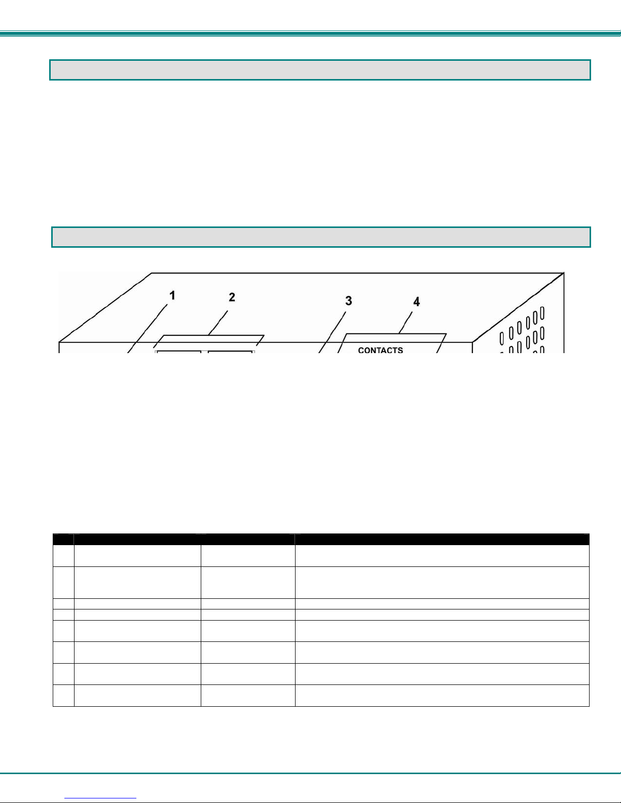
CONNECTORS AND LEDS
LABEL CONNECTOR/LED DESCRIPTION
#
1 5V 2.0A
2 TEMPERATURE/HUMIDITY
3 WATER
4 CONTACTS 1-4
5 PWR
6 FAULT
7 RS232
8 ETHERNET
Note: The RS232 port is not used for configuration purposes.
Note: For model ENVIROMUX-MINI-IND, the power jack is 2.5mm x 5.5mm.
2.1x5.5mm Power
Jack
RJ45 female
connectors
Wire Terminal Block for connection of ENVIROMUX-LD liquid detection sensor
Wire Terminal Block for connecting dry-contact sensors
Green LED illuminates to indicate proper power to the unit and normal operation
Red LED illuminates to indicate a fault condition has been reached at one or
RJ45 Female
connector
RJ45 female
connector
for connection of power supply
for connection of optional ENVIROMUX-T, ENVIROMUX-RH, or
ENVIROMUX-TRH sensors (The right port is "#1", the left port is
"#2" as listed in the Summary Page on Page 14.)
(i.e. indicates that there are no alerts)
more sensors
for connection of a PC for firmware updates (page 28) or connection
of GSM modem (page 10)
for connection to an Ethernet for remote multi-user control and
monitoring
6
Page 11
NTI MINI SERVER ENVIRONMENT MONITORING SYSTEM
INSTALLATION
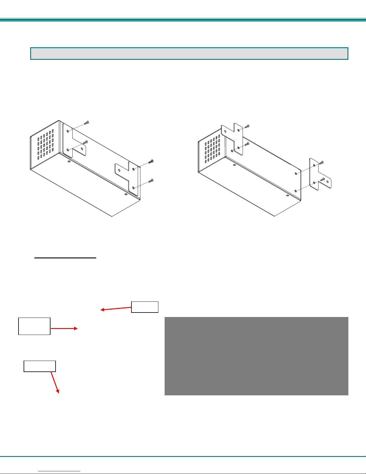
Mount the Unit
The ENVIROMUX-MINI can either be placed on a solid surface, mounted to a wall, or mounted to an accessible surface within
rack (Zero-RU). To mount to a wall or other surface, first remove the screws holding the mounting tabs to the rear of the box.
Rotate the tabs such that they extend from the back of the box, and attach the tabs with the screws removed. Now the
ENVIROMUX-MINI can be secured to any convenient surface. Use appropriate hardware (not supplied) when mounting.
Figure 1- Rotate the tabs for Zero-RU mounting
DIN Rail Mounting
The ENVIROMUX-MINI-D is for mounting to a DIN rails in a server rack. It is supplied with a DIN rail clip on the back. With the
clip installed, it can be readily snapped to a DIN rail and easily removed. Press the side of the clip with the metal spring in it
against the channel, rotate the ENVIROMUX-MINI-D into position, and release the pressure. Reverse the procedure to remove it.
DIN Rail
Bracket
DIN Rail
Spring
Figure 2- DIN Rail clip and unit mounted to a rail
7
Page 12

NTI MINI SERVER ENVIRONMENT MONITORING SYSTEM
Connect Sensors
1. Connect the desired sensors (ENVIROMUX-T, RH, or TRH- sold separately) to the available ports on the ENVIROMUXMINI. Plug the RJ45 connectors to either of the two ports marked "TEMPERATURE/HUMIDITY". The ENVIROMUX-T,
RH, or TRH sensors can be secured anywhere that the temperature and/or relative humidity need to be sensed. Powercycle the ENVIROMUX-MINI after sensors have been plugged-in.
Note: Mounting the sensor in the path of a fan or on a heated surface may affect the accuracy of the sensor’s readings.
Note: For best results, use the ENVIROMUX-T-IND with model ENVIROMUX-MINI-IND (see Sensors, page 11).
Figure 3- Connect sensors to ENVIROMUX-MINI
2. Connect the optional liquid detection sensor (ENVIROMUX-LD- sold separately) to the terminals marked "WATER" or to the
terminals marked “CONTACTS”. The two-wire cable provided can be extended to a total cable length of up to 1000 ft using any
two conductors (minimum 18AWG for 1000 feet).
The twisted orange sensing cable should be placed flat on the surface (usually the floor) where liquid detection is desired. If tape
is required to hold the sensor in place, be sure to only apply tape to the ends, exposing as much of the sensor as possible. At
least 5/8" of the sensor must be exposed for it to function. (See Figure 4)
Figure 4- Secure liquid detection sensor with tape
8
Page 13

NTI MINI SERVER ENVIRONMENT MONITORING SYSTEM
3. Up to four dry-contact sensors or additional liquid detection sensors can also be connected to the terminals marked
“CONTACTS”. Sensors with 16-26 AWG connection wires, that operate on 5V at 10mA maximum current may be used. A
contact resistance of 10kΩ or less will be interpreted by the ENVIROMUX-MINI as a closed contact.
To install the dry-contact sensor(s):
A. Attach the positive lead to a terminal corresponding to a "+5V" marking on the ENVIROMUX-MINI and the ground lead to
the next terminal to the right that will correspond to a marking on the ENVIROMUX-MINI. Tighten the set screw
above each contact. Terminal sets are numbered 1-4.
B. Mount the sensors as desired.
Example:
Device w i th potential-fr e e
break/make contact relay
(i.e. door switch)
Figure 5- Terminal block for contact sensors
+5V
1
+ 5 V
Note: The terminal block is removable for easy sensor wire attachment if needed.
Shielded
cable must be used to connect to the DRY CONTACT ports in order to meet CE emission req uirements.
Connect the drain wire of the shield to the ground ( ) terminal of the dry contact in addition to
To install additional liquid detection sensors, just apply the two wires of the sensor to the +5V and terminals for a
numbered contact. It doesn’t matter which wire goes on +5V or ground when wiring liquid detection sensors.
C O N T A C T S
1 2
+ 5 V + 5 V + 5 V
3
4
the contact return wire.
Connect to Ethernet
Connect a CAT5 patch cable (RJ45 connectors on each end wired pin 1 to pin 1, pin 2 to pin 2 etc) from the local Ethernet
network connection to the connector on the ENVIROMUX-MINI marked "ETHERNET".
Figure 6- Connect ENVIROMUX-MINI to the Ethernet
For direct connection from a PC to the ENVIROMUX-MINI, use a crossover cable. See page 27 for crossover cable
pinout.
Note: The Ethernet port that the ENVIROMUX-MINI is connected to should be configured for 10Mbps half duplex.
Shielded CAT 5,5e, or 6 cable must be used to connect to the ETHERNET and RS232 ports in order to meet CE emission
requirements.
F r o n t V i e w o f E N V I R O M U X - M I N I
T E M P E R A T U R E / H U M I D I T Y
5 V
2 . 0 A
P W R
S E N S E S E N S E
N T I
N e t w o r k T e c h n o l o g i e s In c
E N V I R O M U X
A R E A A L E R T
R J 4 5 - m a l e
c o n n e c t o r
W A T E R
R
C O N T A C T S
3
1 2
+ 5 V
T M
T M
R S 2 3 2 E T H E R N E T F A U L T
+ 5 V + 5 V + 5 V
4
E t h e r n e t
9
Page 14

NTI MINI SERVER ENVIRONMENT MONITORING SYSTEM
Connect the Power
Note: Sensors should be connected before supplying power to the ENVIROMUX-MINI.
1. Connect the AC adapter to the connection marked "PWR" on the ENVIROMUX-MINI and plug it into an outlet.
B a r r e l
5 V D C
A C
A D A P T E R
Note: The power
connector for the
ENVIROMUX-MINI-IND
has a 2.5mm x 5.5mm
female barrel
P o w e r C o n n e c t o r
5 V D C @ 2 . 0 A O U T P U T
( O u t s i d e
b a r r e l )
2 . 1 m m x 5 . 5 m m F e m a l e
( I n s i d e
b a r r e l )
Figure 7- Connect the AC adapter and power-up
2. Use the NTI Discovery Tool (page 13) to configure network settings.
F r o n t V i e w o f E N V I R O M U X - M I N I
T E M P E R A T U R E / H U M I D I T Y
5 V
2 . 0 A
P W R
S E N S E S E N S E
N T I
N e t w o r k T e c h no lo g i e s I n c
E N V I R O M U X
A R E A A L E R T
W A T E R
R
T M
T M
C O N T A C T S
1 234
+ 5 V
+ 5 V + 5 V + 5 V
R S 2 3 2 E T H E R N E T F A U L T
Connect a Modem
Note: This feature requires firmware version 1.31 or higher to use ENVIROMUX-GSM(A)-P (Teltoni ka CM1100 or Multitech
MTCBA-G-F4), or version 1.36 or higher to use ENVIROMUX-3G (NetComm N3GS003).
A Serial GSM modem may be connected (ENVIROMUX-GSM-P / ENVIROMUX-GSMA-P) or a 3G Serial Modem (ENVIROMUX3G) to use to send SMS alert messages to a contact’s cell phone.
• The ENVIROMUX-GSM-P and ENVIROMUX- 3G modems will connect to the ENVIROMUX-MINI at the “RS232” port
The phone number of the contact person can be configured on the sensor configuration page (page 21).
Note: A Mini SIM card (not included) must be installed in the modem for the modem to send messages.
using a CAT5 patch cable and a NTI DB9M-RJ45F-EM adapter (supplied with modem). (See Figure 8.)
• The ENVIROMUX-GSMA-P modem will connect at the “RS232” port using the 15HDM-RJ45F-EM adapter (supplied with
modem).
Figure 8- Connect a Modem
Note: The RS232 port is also used to perform firmware updates (page 28). The RS232 port is not used for configuration
purposes.
10
Page 15

NTI MINI SERVER ENVIRONMENT MONITORING SYSTEM
OVERVIEW - USE AND OPERATION
The ENVIROMUX-MINI is controlled via a web interface using a browser, which is for viewing an d configuring sensor
data and system settings. A sensor summary page allows the user to view the connected sensors’ current values, threshold
settings and alert statuses. Individual sensor status pages are available for each connected sensor. Also, the user can view
recorded sensor readings that have been stored in the system data log.
The web interface allows for the configuration of the thresholds for all attached sensors, their alert methods, and the
formats of the alerts. In addition, network information (IP address, subnet mask, default gateway, DNS, etc.), user administrative
settings, and data logging settings can also be configured. All settings are saved in memory when applied. A user may also
restore the unit to its default settings via the web interface or the Restore button on the ENVIROMUX-MINI (see page 27).
Sensors
The ENVIROMUX-MINI provides two Temperature/Humidity sensor inputs, both RJ45 jacks. Available sensor
configurations include Temperature (ENVIROMUX-T), Humidity (ENVIROMUX-RH), or Temperature+Humidity (ENVIROMUXTRH). For the ENVIROMUX-MINI-IND for best results use temperature sensor ENVIROMUX-T-IND (see note below).
The ENVIROMUX-T temperature sensor is capable of measuring temperatures from 32°F to 104°F, with an accuracy of
±1.35°F (0°C - 40°C , ±0.75°C). Temperature can be displayed in either Celsius or Fahrenheit. The humidity sensor is capable of
measuring relative humidity percentages ranging from 20-80% with ±5% accuracy over the sensor temperature range.
Note: ENVIROMUX-T-IND temperature sensor (for the ENVIROMUX-MINI-IND) has a temperature range of 32°F to
167°F (0°C - 75°C). The ENVIROMUX-T/RH/TRH sensors can be used with the ENVIROMUX-MINI-IND, but they will not be
accurate above 104º F.
The temperature/humidity sensors have been given factory default settings and thresholds that can be changed (see
page 16). Sensor readings can be reported continuously, only when readings change, or at a regular rate (for instance, a
temperature reading could be updated once each hour).
Sensors connected to the terminals labeled "CONTACT" must be manually configured, and can be any sensor of
contact-closure / open-collector type that operate on 5VDC and 10mA, with a maximum load resistance of 10kΩ or less.
The liquid detection sensor (ENVIROMUX-LD) will warn the user(s) of flooding. It will detect and report the presence of
any conductive liquid (typically water) covering an area at least 5/8 inch in diameter and 1/8 inch deep.
IP Assignment
An IP address can be assigned to the ENVIROMUX-MINI through either of three methods:
• Using the NTI Discovery Tool (page 13)
• Manually through the web interface on the Network page (page 16)
• Automatically by a DHCP server (page 16)
Initially, IP configuration will be the easiest to change using the NTI Discovery Tool (found on the CD), which will search
for NTI devices on the user’s network and allow IP assignment to them through its web interface. Other settings for subnet mask
and default gateway may also be configured (see page 13). These settings must be configured properly in order to access the
ENVIROMUX-MINI web interface. Default settings are shown in Figure 13 on page 16. Alternatively, the network settings can
be assigned automatically by a DHCP server, as indicated on page 16.
User Management
The ENVIROMUX-MINI supports up to 8 user accounts and one Guest account (page 20). Each user account is
protected by local password authentication. Each user may be assigned "User" or "Administrative" privileges. Users accessing
the Guest account will be granted access to only the monitoring functions, and will be able to view the log. An account with "User"
privileges may view and configure sensor settings, the log, general system settings, email settings, time settings, and their own
user password. An account with "Administrative" privileges has all of the privileges of a "User" account, in addition to being able
to view and configure network settings, add/edit/delete other user accounts, and enable/disable the Guest account.
Alerts
A high and low threshold limit can be set for each temperature or humidity sensor within the operating range of the
sensor. Each open collector/contact-closure sensor can be set as normally-open or normally-closed. When a sensor takes a
reading that is outside a threshold or a contact-closure sensor is not in its normal condition, an alert notification can be generated.
The user can specify how often and the maximum number of alert notifications to be provi ded. Also, there is an adjustable
hysteresis involved with alert notifications. This means if a sensor’s readings are moving in and out of the threshold boundaries
within a configurable period of time, additional alert notifications will not be sent. Alerts ma y be sent if the condition of the sensor
returns to normal or back within its threshold boundaries. Alert notifications (page 24) will be provided throug h any or all of these
methods:
• visible notification via the user interfaces (red LED on front panel, alert on webpage)
• emails
• SNMP Traps
• Syslog messages
• SMS messages
11
Page 16

NTI MINI SERVER ENVIRONMENT MONITORING SYSTEM
Data Logging
viewed at any time through the web interface (page 23). Additionally, as entries are generated, they can be emailed or sent as
SNMP traps. Entries can be deleted from the log via the web interface. The maximum size of the data log is 100 entries. The log’s
behavior upon reaching this maximum size can be configured, allowing the log to either wrap (overwrite oldest entries), or stop
logging. The entire log can be downloaded as a plain text file from the web interface at any time (see "View the Log" o n pag e
23).
Email
alert notifications or data log messages. The user can configure what conditions cause emails to be sen t. The ENVIROMUXMINI’s email address, as well as SMTP server information and the email addresses to which emails are sent, can be configured
on the Email page through the web interface (page 17). Up to 3 outgoing email addresses (112 characters maximum including
commas) may be configured. Only an unauthenticated email address can be used to send email.
SNMP
events. Using an SNMP MIB browser, a user can monitor all sensor statuses and system IP settings, as well as configure sensor
thresholds, sensor names, and the system name. The destination for SNMP traps can be configured on the Network page
(page 16).
Note: The SNMP MIB file (enviromux-mini.mib), for use with an SNMP MIB browser, can be found on the manual CD.
Click on the link to open the file, then save the file to your hard drive to use with the SNMP MIB browser.
Syslog
The ENVIROMUX-MINI can log sensor readings, sensor alerts, alert handling, and user logins/logouts. The log can be
The ENVIROMUX-MINI can access an outgoing SMTP server to send email. Outgoing mail may co ntain pre-formatted
The ENVIROMUX-MINI can send alerts as SNMP traps (V1) when a sensor enters/leaves alert mode, and for all log
The ENVIROMUX-MINI can send alerts as Syslog messages when a sensor enters/leaves alert mode, and for all log
events. The destination for Syslog can be configured on the Log Methods page (page 24) .
SMS
The ENVIROMUX-MINI can send alerts as SMS message when a modem (GSM or 3G Serial) is connected (page 10).
The phone number destination for all SMS messages is configured on the sensor configuration page (page 21).
Note: Only one phone number can be used. If the phone number is changed for one sensor, the change is automatically
applied to all sensors.
Note: This feature requires firmware version 1.31 or higher.
WAP
The ENVIROMUX-MINI can be accessed to view the summary page for sensor status from a mobile phone with WAP 2.0
support (see page 26).
Note: This feature requires firmware version 1.34 or higher.
Power-on/Reset Operation
On power-up, after going through its boot sequence, the ENVIROMUX-MINI will launch the monitoring application, load
any stored configuration values, and immediately identify and begin taking readings from any connected sensors. Alerts will be
reported using the configured alert methods, and data will be logged using the stored preferences. A user can log in at any time
after the system has launched the monitoring application (approximately 5 seconds after power is applied) to view and configure
properties of the system and its sensors.
Note: It is normal for the red LED (Fault Indicator) to be illuminated for a few seconds upon startup.
Out-of-Box Operation
The operation of the unit directly out of the box is nearly identical to the Power-on/Reset operation. However, information
about the unit will only be able to be monitored and controlled once valid network settings are assigned to the device (see IP
Assignment on page 11). The network settings must be compatible with the physical network to which the ENVIROMUX-MINI is
attached. Also, alert notifications will only be able to be viewed through the user interfaces (LED, web page). Email and SNMP
alert notifications must be configured within the web interface (page 16) before these methods can be used. Once these
configurations are made, they will be saved in the unit, even if the ENVIROMUX-MINI is powered-OFF.
12
Page 17

NTI MINI SERVER ENVIRONMENT MONITORING SYSTEM
DEVICE DISCOVERY TOOL
In order to easily locate the ENVIROMUX-MINI on a network, and change the IP settings, the NTI Device Discovery Tool may be
used. A link to the Discovery Tool is provided on the web page that appears when the instruction manual CD is inserted into the
computer's CD ROM drive. Click on the link or browse the CD and click on the file discover.html . This will open a browser and
display the Device Discovery Tool page.
Note: The Discovery Tool requires the Java Runtime Environment to operate. A link to the web page from which it can
be downloaded and installed is provided on the CD. A Windows compatible version of the software is also on the CD.
Note: The ENVIROMUX-MINI and the computer using the Device Discovery Tool must be connected to the same physical
network and in order for the Device Discovery Tool to work.
Note: There cannot be a firewall between the computer using the Device Discovery Tool and the ENVIROMUX-MINI. If a
firewall is present between them, the Device Discovery Tool will not work.
Figure 9- Device Discovery Tool page
Use the Device Discovery Tool to display all NTI devices on your network, along with their network settings. Follow the
instructions on the Device Discovery Tool page to use the tool and to change the device settings if so desired.
Note: If the IP address is set to be obtained automatically from a DHCP server (see page 16, Figure 13), then the IP
address will not be able to be manually changed. If an attempt is made, the DHCP server will automatically change it
back to the automatically assigned address.
FYI: The "Blink LED" button will
blink the green "PWR" LED on the
ENVIROMUX to identify which unit is
associated with the settings shown.
13
Page 18

NTI MINI SERVER ENVIRONMENT MONITORING SYSTEM
USE AND OPERATION VIA WEB INTERFACE
A user may monitor and configure the settings of any device connected to the ENVIROMUX-MINI using the Web Interface via a
web browser (see supported browsers on page 6). To enable the Web Interface, connect the ENVIROMUX-MINI to the Ethernet
(page 9). A user can login to the default IP address (shown below), or if the IP address is not known, use the Device Discovery
Tool (page 13) to determine and, if desired, setup the network settings. In either case, to access the web interface controls, the
user must log in.
Log In
To access the web interface, type the current IP address into the address bar of the web browser. (The default IP address is
shown below):
Note: If the HTTP Server Port number is changed (page 16) from port 80 (default), then the port number will need to be
added to the IP address (i.e. if the port number is changed to 95, then the IP address would be http://192.168.1.21:95)
A log in prompt requiring a username and password will appear:
Username = Administrator
(uppercase letter for "A"
only)
Password = admin
(lower case letters only)
Note: usernames and passwords are case
sensitive
http://192.168.1.21
Figure 10- Login prompt to access web interface
With a successful log in, a screen similar to the following will appear:
Figure 11- Administrator's Status Summary page and menu
14
Page 19

NTI MINI SERVER ENVIRONMENT MONITORING SYSTEM
The initial web interface page includes a status summary showing the present name, type, value, an d status of each sensor
attached to the ENVIROMUX-MINI. It also includes a menu to the left of the screen from which the administrator can select
pages that will allow them to:
• change the general settings of the ENVIROMUX-MINI
• configure network settings
• perform user management to control who has access to the sensor information
• configure each of the sensors
• configure the ENVIROMUX-MINI for how it will report sensor alerts and to whom
• configure sensor event log recording
FYI: If a user tries to log in with a username already logged in at another IP address, the user will be presented with
"The user <username> is already logged in at IP address <IP address>. If you continue, <username> will be logged out.
Continue?". Select the "Yes" or "No" button. Selecting "Yes" will log out the first user. Selecting "No" will take the
user back to the log in page (or summary page if Guest is enabled (page 15)).
To login using a WAP 2.0 compatible device, see page 26 .
General Settings
Figure 12- General menu for administrative settings
From the General menu under ADMINISTRATION, the user can make changes as follows:
• Firmware Version
• Node Name-
• Node Location-
• Update sensor status
pages-
• Restore-
• Reboot-
Press Apply if any changes are made above to the fields or the changes will not be save d upon leaving this page.
Note: If the Restore or Reboot buttons are pressed, the ENVIROMUX-MINI will erase the system logs. It is
recommended that the logs be downloaded if they need to be saved before using the Restore or Reboot buttons
(see page 23 to download System Logs). If the TIMEP server is not configured (page 18), the manually set time will
be incorrect after using these buttons.
current firmware version of the ENVIROMUX-MINI
change the name of the ENVIROMUX-MINI. The Node Name will appear in SNMP trap
messages to enable the user to identify the source of the alert
assign a reference location (where the ENVIROMUX-MINI is located). The Node Location will
also appear in SNMP trap messages to aid in user identification of the source of the alert.
configure how often the sensors will have data updated on the summary page
restore the ENVIROMUX-MINI to all factory default settings including usernames, passwords, and
all network and sensor settings.
reboot the ENVIROMUX-MINI- refreshing settings and communications (this does not restore
default settings)
15
Page 20

NTI MINI SERVER ENVIRONMENT MONITORING SYSTEM
Network Settings
The Network Settings screen (see Figure 13) is available only to the administrator or users with administr ative privileges. Once
the settings have been changed, press the Apply button for changes to take effect. The new settings will take effect immediately
and the user will need to log in again to continue the interface with the ENVIROMUX-MIN I. If a mistake has been ma de and the
user cannot find the ENVIROMUX-MINI by entering the new IP address in the address bar, the Discovery Tool may be used to
locate and correct the address of the ENVIROMUX-MINI (see page 13).
Figure 13- Network configuration page (defaults shown)
Network settings include:
• MAC Address
• IP Address
• Subnet Mask
• Gateway
• DNS Server
• HTTP Server Port
• Enable SNMP
• SNMP Community
• SNMP Trap Destination
Note: After any change in Network settings, the ENVIROMUX-MINI will reboot.
factory assigned MAC (Media Access Control) address - no changes are allowed in this field
unique IP address for the ENVIROMUX-MINI, assigned by the network administrator
(or select “Obtain an IP address automatically” to have a DHCP server assign the IP address)
for the ENVIROMUX-MINI, assigned by the network administrator
of the ENVIROMUX-MINI, assigned by the network administrator
used by the ENVIROMUX-MINI, assigned by the network administrator
can be changed to a secure port channel, assigned by the network administrator
select to enable SNMP alert message generation
default is "public" or assign per your local needs
specify the IP Address of the computer that will receive SNMP traps
16
Page 21

NTI MINI SERVER ENVIRONMENT MONITORING SYSTEM
Email Configuration
Figure 14- Email configuration page
The Email Page allows users to configure the necessary settings that enable the ENVIROMUX-MINI to send emails vi a an SMTP
server. It requires the following settings:
• ENVIROMUX-MINI Email Address- Defines the content of the "From" field in the email messages sent by ENVIROMUX-
MINI.
Note: Some SMTP servers may not accept invalid email addresses and may block some domain names. Be sure that
the address is accepted by the SMTP server
Note: The ENVIROMUX-MINI will not work on a network whose SMTP server requires password authentication. The
ENVIROMUX-MINI is not designed to submit a password when sending alerts via email.
• SMTP Server- Defines the outgoi ng SMTP server by its DNS name or numeric IP address.
• Notify addresses- Defines the email addresses of recipient(s). Addresses (up to 3) must be separated by comma. A
maximum of 112 characters (including commas) is accepted in this field.
Note: Improper configuration of these fields may temporarily cause the ENVIROMUX-MINI to stop working. To
troubleshoot email configuration problems, check for one or more of the following:
• The indicated SMTP server name is incorrect.
• The unit cannot reach the DNS server and cannot look up the numeric IP.
• The DNS Server is entered incorrectly in the Network Settings Page.
• The SMTP server does not accept the ENVIROMUX-MINI Email Address.
• All values are entered correctly, but the unit cannot reach the SMTP server for network routing reasons.
IE: In the SMTP Server field, smtp.mydomain.com_ the extra space at the end of the address will cause a
failure.
17
Page 22

NTI MINI SERVER ENVIRONMENT MONITORING SYSTEM
Date and Time
Figure 15- Date and Time configuration page
The Date and Time page in the ADMINISTRATION menu enables the administrator to either manually set the date and time or to
have the ENVIROMUX-MINI synchronize with a TIMEP server. If a TIMEP server is specified, the ENVIROMUX-MINI will
synchronize with the TIMEP server every 10 minutes. The format in which the date is displaye d on other pages can be configured
with the Format box.
Note: If a TIMEP server is not specified, then the user will need to manually update the date and time any time the
ENVIROMUX-MINI loses power.
• Current Date and Time- to change the time zone used for the unit, select the desired time zone. In ord er to have the time
change in accordance with the new Daylight Saving Time rules (passed in 2005), a checkmark must be placed in the block
“Automatically adjust clock for daylight saving changes”
• Synchronize with TIMEP Server- used to specify a TIMEP server with which to synchronize the system time. Select the
radio button and enter either the domain name or IP address of the desired time server
• Change Date/Time Manually- to manually change the date and/or time, select the radio button and enter the desired date
and/or time into the "Date" and "Time" boxes
When entering the date manually, be sure to specify it in the format chosen. Similarly, when
entering the time manually, be sure to enter it in the format (hh:mm:ss). where HH is a two
digit hour, MM is a two digit minute, and SS is a two digit second.
• Options- the choices in the "Options" section operate as follows when the date and/or time is changed:
• Do not change sensor records – log times and sensor record times will not be adjusted to the
new times (default)
• Reset sensor records – sensor records will be reset and will begin recording from the ne w
time
• Adjust sensor records – log times and sensor record times will be adjusted to be relative to
the new time
18
Page 23

NTI MINI SERVER ENVIRONMENT MONITORING SYSTEM
User Management
From the User Management screen in the ADMINISTRATION menu, the administrator can set and change all passwords, set up
to four user accounts (with or without administrative rights), and enable a non-user to view the Status Summary page by selecting
the "Enable Guest" field.
Figure 16- User Management for controlling user access
• To add a new user- enter the information for the user in the "Add User" section, and click the Add User button. The
username should appear in the user list in the "Edit User" section.
• To edit the u sername p assword, or privileges of any user- click on the name of the desired user in the user list, and enter
the new information for that user in the fields "For the selected user…", then click the Apply button. Fill only the fields that
require change when editing a user.
Usernames can be from 1-32 characters in length and include most characters. They cannot contain a backslash ( \ ) or
quotation mark ( " ).
Passwords can be 5-32 characters in length and can be the same types of characters as the username.
A user can be classified as a "User", with only user privileges, or as an "Administrator", with full administrative privileges.
Note: Be careful who is indicated as an administrator instead of as a user. Anyone listed as an admin istrator has full
access to change anything
In the event administrator password(s) are lost, see pages 15 or 27 for "Restore Defaults" to restore the ENVIROMUX-MINI to all
factory default settings.
as if they were the administrator.
User Privileges
A user with "User" privileges that has logged-in to the ENVIROMUX-MINI is able to:
• view and change the sensor report settings
• view and delete the contents of the events log
• view and change the General, Email, and Date & T ime settings from the ADMINISTRATION menu
A user has much of the same control as the administrator, except that the user cannot add more users, cannot change any
password except their own password, and cannot change network settings.
A user will be logged out of the web interface after 20 minutes of inactivity. The page being viewed will remain until the user
attempts to move elsewhere in the web interface, at which point a new LOG IN prompt will appear.
19
Page 24

NTI MINI SERVER ENVIRONMENT MONITORING SYSTEM
Guest User
If the "Enable Guest" field is checked under User Management (page 19), then the Summary page (F igure 17) will be displayed
any time the IP address is placed in the browser's address bar.
Figure 17- Status Summary and menu for Guest users
On this screen the status of each sensor connected to the ENVIROMUX-MINI is displayed. The guest may view the system log
and the status of any sensor. To be able to configure system settings, the user must log in. Click on the "LOG IN" link at the
bottom left of the menu. A prompt will appear calling for a username and password to be entered.
20
Page 25

NTI MINI SERVER ENVIRONMENT MONITORING SYSTEM
Sensor Management
In the SUMMARY page each of the sensors attached to the ENVIROMUX-MINI are listed. To view the details of a particular
sensor, click on the sensor name in the left column of the screen.
Figure 18- Specific sensor information
From here the user can see the threshold settings (in red) and the current reading (in green) of a selected sensor. It also shows
the time, date, and measurement taken of the most recent alert, as well as the lowest and highest reading taken by the sensor
since it was last powered on(if the sensor is an ENVIROMUX-T / RH / or TRH). If the sensor is a dry-contact type, the contact
condition and most recent alert will be indicated.
To modify the sensor's attributes (thresholds, alert methods, name, etc.), click on the Configure button. A screen like the
following will appear (format may vary depending upon the type of sensor):
Suggestion:
Once the timing, thresholds, etc.
are configured for a sensor, use
the Test Alerts feature and press
“Simulate Alert” to test the
configuration, making sure that
events and communications
through email ,SMS, SNMP, and/or
Syslog occur as desired. Once this
is determined to be satisfactory,
press “Clear” to resume normal
operation of the sensor.
Figure 19- Sensor alert record configuration
21
Page 26

NTI MINI SERVER ENVIRONMENT MONITORING SYSTEM
Name
Each sensor can be named. Names can be from 1-32 characters in length and include most characters. They cannot contain a
backslash ( \ ) or quotation mark ( " ).
Thresholds
The high and low threshold of proper operating temperatures and/ or humidity can be configured. If the sensor readings go
above or below these settings, an alert can be communicated in a predetermined way (see Alert Methods below). Readings
from a dry-contact sensor can be configured to cause an alert to be sent if the contact position changes (open or closed).
Alert Timing
The hysteresis of the alert timing can be adjusted. This means that a recurrence of an alert can be delayed in the event the
readings from a sensor only fall above or below the threshold levels for the specified period of time. The time period can be set
for 1-9999 seconds or minutes.
A time period can be set for how long to wait before repeating an alert message after the first message is sent when the sensor
remains in an alert condition. The repeated alert can be set to occur from 1-9999 seconds, minutes, or hours.
The user can be notified when the sensor readings have returned to the normal range by selecting the "Notify on return to normal"
box for a sensor.
The user can set the number of alert messages that can be sent for each sensor per alert condition. As few as 1 and as many as
255 can be set, or enter “0” to disable the limitation and enable an unlimited number of messag es.
The user can choose to have alerts be automatically acknowledged when conditions return to normal by selecting the
“Automatically acknowledge alert when condition clears” box for a sensor.
Alert Methods
The alert can be configured to notify a user via email, SMS, SNMP traps (V1), or Syslog messages. Alerts are also indicated on
the FAULT LED on the front of the ENVIROMUX-MINI and in the WEB interface on the Summary Page.
Email
For the ENVIROMUX-MINI to send an email alert, the Email settings (on the “Email” page) and the IP address of the DNS server
(on the “Network” page) must be properly configured. Put a checkmark in the "Email" box to enable this option. The email
addresses chosen for alerts from the Email configuration page will be pre-filled in the text box below the check box. The email
addresses may be changed on this page as well. Simply enter the desired email addresses (maximum of 112 characters
including commas) and click Apply.
Note: If the email addresses are changed on this page, they will also be automatically changed on the Email page.
SNMP
For an SNMP trap to be sent, put a checkmark in the "SNMP" box. The SNMP trap destination IP address from the Network
configuration page will be pre-filled in the “Notify address” box below. The IP address can also be changed from this page.
Simply enter the desired SNMP trap destination IP address and click Apply.
Note: If the IP address is changed on this page, it will also be automatically changed on the Network page.
Syslog
The ENVIROMUX-MINI can send alerts as Syslog messages when a sensor enters/leaves alert mode, and for all log
events. For a Syslog message to be sent, put a checkmark in the "Syslog" box. Enter an IP address in the “Notify address” box
below and click Apply.
SMS
A GSM or 3G modem must be connected to the ENVIROMUX-MINI in order to send alert messages using SMS (page 10). With
the modem properly connected and powered ON, the ENVIROMUX-MINI should display the word “Ready” in the box for “GSM
Modem Status. To enable SMS alerts, place a checkmark in the “SMS” block and apply a valid cell phone number i n the block
provided.
Note: This feature requires firmware version 1.31 or higher.
22
Page 27

NTI MINI SERVER ENVIRONMENT MONITORING SYSTEM
Message to Send with Alerts
A message may also be applied to email, SMS and SNMP alerts. The message is optional and may contain up to 160 characters.
The same message is used for each alert method. If neither of these alert methods are chosen, alerts for the sensor will only be
shown on the sensor’s status page and indicated with the red “Alert” LED.
The alerts for a sensor can also be disabled completely by selecting the "Disable alerts for this sensor" box.
System Log
Information collected from any of the ENVIROMUX-MINI sensors, as well as from other system events, can be stored in a log and
reviewed by anyone (Administrator, User, or Guest).
View the Local Log
From the LOG menu, select View Log.
Figure 20- View the local event log
A list will appear displaying each event that has been recorded by the ENVIROMUX-MINI, according to the criteria establis hed
under "Events to Log" (page 24). Each record can be left as it is for future viewing, or deleted from the list.
To delete a record
To delete only the entries on the page of records being viewed
To delete all of the records on all pages of the log, click on Delete Entire Log.
To download the log to the local computer
for easy importing into Microsoft Excel and other spreadsheet programs. To quickly view the log text file, ope n with Wordpad or
MSWord.
The number of entries viewed per page can be 10, 20, 30, 40, 50, or ALL. The percentage of total Log space remaining is noted
above the table. If records are not deleted manually, then at some point the Log will overflow with messages. See "Overflow
Actions" on page 25.
FYI: Another quick way to delete log records is to power-OFF or reboot the ENVIROMUX-MINI. The log will be erased if
power is disrupted.
, select the line from the box in the left column, and click on Delete Selected.
, click on Select All and then Delete Selected.
, select Download Log. The log is saved as a tab-delimited text file that is formatted
23
Page 28

NTI MINI SERVER ENVIRONMENT MONITORING SYSTEM
Events to Log
The Events to Log page enables the user to specify what type of events sensed by the ENVIROMUX-MINI should be recorded in
the Log. The user can select each type of event that should be recorded and can change these selections at any time. Events
that can be logged include sensor readings, alert conditions, actions taken by the user in response to an alert, end of alert
conditions, and user logging in or out of the ENVIROMUX-MINI web interface. The log can also be disabled altogether.
Within the Sensor Readings section, the rate at which readings are logged can also be configured to either:
• log the status each time the sensor reading updates internally
• log the status every 1-999 seconds, minutes, or hours
• log the status only if the status/reading from the sensor has changed
Within the Alert Conditions section, the user can choose the sensors whose alerts should be recorded, as well as whether or not
those alert records should be followed up with a record indicating the end of the alert condition.
Alert Actions (actions taken by the user in response to an alert), whether they are dismissed, or acknowledged, can be logg ed by
making the appropriate selection.
After selections have been made, press Apply to save them or Cancel to start over.
Figure 21- Configure events to be logged
Log Methods
Within the Log Methods page (Figure 22), the user can define how, if at all, they will receive notification of events that are
recorded by the ENVIROMUX-MINI. The options are as follows:
• Local – log entries are stored in the ENVIROMUX-MINI and are viewable from the user interface
• Email – all log entries generated by selections on the “Events to Log” page are emailed to the email addresses indicated in
“Notify addresses”
• SNMP – every log entry created is sent as an SNMP trap to the address in “Notify addr ess"
• Syslog –
events. Logs entries are sent to the address in "Notify address"
The field under “Notify Addresses” will contain the email addresses from the Emai l configuration page (with a maximum of 112
characters including commas). Similarly, the SNMP trap and Syslog destination addresses in “Notify Address” will contain the
corresponding destination addresses from the Network configuration page. All fields may be changed from this page as well.
the ENVIROMUX-MINI can send alerts as Syslog when a sensor enters/leaves alert mode, and for all log
24
Page 29

NTI MINI SERVER ENVIRONMENT MONITORING SYSTEM
Note: If the Notify address for either the Email or SNMP
fields is changed, the same fields entered on the Email and
Network pages will also be automatically changed.
Select the desired options and click on Apply to save them.
Figure 22- Define log methods
Overflow Actions
There is a maximum limit of 100 event records that can be stored in the ENVIROMUX-MINI. The Overflow Action page enables
the user to configure how the ENVIROMUX-MINI handles records when log memory capacity is exceeded.
The user can choose to be alerted or not by
Email, SNMP, and/or Syslog. The message in
“Message to send” will be sent in the Email,
Syslog or with the SNMP trap. The message is
sent when the log reaches 90% capacity, to
provide time for the user to receive the alert and
take any necessary action before the log
overflows.
When the log overflows, the user can either have
the log stop recording by selecting "Discontinue
log", or have the oldest records in the log
overwritten with the newer records by selecting
"Wrap log".
With the selections made, press Apply for the
selections to take effect.
Figure 23- Overflow actions-when the log is too large
SNMP MIB Configuration
An SNMP Management Information Base (MIB) file is provided on the CD for use with a third-party MIB browser. The MIB can be
loaded with an MIB browser (version 1 supported, but not supplied) and may be used to retrieve sensor statuses and system
settings, configure sensor thresholds, and configure the system name and location. The ENVIROMUX-MINI responds to GET,
NEXT, and SET requests. The Enable SNMP check box must be selected on the Network configur ation page from the
ADMINISTRATION menu.
25
Page 30

NTI MINI SERVER ENVIRONMENT MONITORING SYSTEM
WAP Login
The user can login to the ENVIROMUX-MINI through a WAP 2.0 compatible device (firmware version 1.34 or higher required) to
view a Summary Page for the sensor status (below). To login, type the current IP address of the ENVIROMUX-MINI into the
address bar of the WAP browser and add the word “mobile” (default IP address used in the example below):
http://192.168.1.21/mobile
Note: If the HTTP Server Port number is changed (page 16) from port 80 (default), then the port number will need to be
added to the IP address (i.e. if the port number is changed to 95, then the IP address would be
http://192.168.1.21:95/mobile)
A log in prompt requiring a username and password will appear:
Username = Administrator
(uppercase letter for "A" only)
Password = admin
(lower case letters only)
Note: usernames and passwords are case sensitive
Note: The user will not be required to login if the Guest account
is enabled (page 19).
Figure 24- WAP Login page
With a successful login, a screen similar to the following will appear. This is the only information that can be accessed through the
WAP 2.0 interface. Select “Refresh” to refresh the information on the display. Select “Log out” when you are finished viewing
the information.
Note: The display will refresh automatically based on the refresh rate set on the “General” page (page 15) in the field
“Update Sensor Status Pages every...” (firmware version 1.35 or higher required)
Figure 25- WAP Summary page
26
Page 31

NTI MINI SERVER ENVIRONMENT MONITORING SYSTEM
PC-TO-ENVIROMUX-MINI CROSSOVER CABLE
In order to make a direct connection between a PC and the ETHERNET connector of the ENVIROMUX-MINI, a crossover cable
must be used. The cable is made with CAT5 cable terminated with RJ45 connectors and wired according to the chart below.
Pin assignment at
Standard End
Wire Color Pin assignment at
Crossed End
1 White/Orange 3
2 Orange 6
3 White/Green 1
4 Blue 4
5 White/Blue 5
6 Green 2
7 White/Brown 7
8 Brown 8
Standard
End
Crossed
End
Crossover Cable
RESTORE DEFAULTS
In the event that the ENVIROMUX-MINI needs to be returned to all default settings, either the web interface, or the Restore button
on the front of the ENVIROMUX-MINI (see Figure 26) can be used.
To use the Restore button,
1. Power OFF the ENVIROMUX-MINI
2. Press and hold the Restore button using a pen or other pointed object,
3. Power ON the ENVIROMUX-MINI,
4. Continue to hold the button for 10 seconds,
5. Release the button.
P W R
R e s t o r e B u t t o n
T E M P E R A T U R E / H U M I D I T Y
F r o n t V i e w o f E N V I R O M U X - M I N I
S E N S E S E N S E
N T I
N e t w o r k T e c h n o lo g i e s I n c
E N V I R O M U X
W A T E R
R
1 2
+ 5 V
T M
R S 2 3 2 E T H E R N E T F A U L T
C O N T A C T S
3
+ 5 V + 5 V + 5 V
4
Figure 26- Location of the Restore button
27
Page 32

NTI MINI SERVER ENVIRONMENT MONITORING SYSTEM
UPDATE THE FIRMWARE
It may be desired, on occasion, to update the firmware in the ENVIROMUX-MINI, or even to change the MAC address of the unit.
To Update the Firmware
The following is needed:
• 1 CAT5 patch cable (maximum 25 feet in length) wired straight thru (pin to pin)- 5 foot cable supplied
• 1 DB9 female to RJ45 female adapter (to connect the CAT5 cable to a communication port on a PC)-supplied
• The firmware file minienv-rev1.xx.hex downloaded from http://www.networktechinc.com/enviro-mini.html
( The current firmware file as of this printing is minienv-rev1.41.)
Note: For model ENVIROMUX-MINI-IND, download the firmware file ” minienv-ind-rev1.xx” instead.
• A PC with an available DB9 male communication port and HyperTerminal loaded
Procedure:
1. Attach the DB9 to-RJ45 adapter to the 5 foot patch cable
2. Disconnect power from the ENVIROMUX-MINI
3. Connect the port labeled "RS232" on the ENVIROMUX-MINI to a serial port on the PC using the CAT5 patch cable with
adapter (see page 29 for pinout of this adapter).
4. Open HyperTerminal and connect to the ENVIROMUX-MINI through the PC, (port settings 57600 / 8-N-2 /no flow).
5. Press and hold the Spacebar on the keyboard of the PC
6. Apply power to the ENVIROMUX-MINI
7. Continue to hold the Spacebar on the PC until the prompt "eZ80L92>" appears.
8. Release the Spacebar.
9. Press 'C' to clear the existing firmware. You will be prompted to either press Enter to continue, or any other key to
cancel. When erasure is complete, the prompt "eZ80L92>" appears.
10. Press 'L' to load the firmware file from the PC.
When prompted by the message "Start sending file via Xmodem protocol...'" from the HyperTerminal menu bar
• choose Transfer (from the HyperTerminal menu bar),
• choose Send File...,
• browse to the minienv-rev1.xx.hex file
• choose the Xmodem protocol (from the scroll menu of the popup window),
• press Send from the popup window
10. Wait until the transfer is complete (the dialog window will close itself). The message " The Vector Table @8000h:
installing..." will appear on the PC.
Note: If this transfer fails, press the 'C' key to clear any loaded firmware and press 'L' to start loading again.
11. Firmware update is complete. Connect to the ENVIROMUX-MINI as normal.
To Change the MAC address
If you need to change the MAC address,
1. Follow only steps 1-8 in the section "To Update the Firmware" above.
2. Press '"M" to enter new MAC address.
3. A prompt for a new MAC address will appear. Enter the characters desired. The colon separators will be automatically
applied.
4. If a mistake is made, finish the characters and then press "M" again to start over.
5. When finished, follow the Restore Defaults procedure on page 27.
28
Page 33

NTI MINI SERVER ENVIRONMENT MONITORING SYSTEM
SPECIFICATIONS
Ports
Temperature/Humidity Inputs Two female RJ45 connectors for connecting temperature sensors, humidity sensors, and/or
combined temperature/humidity sensors.
Note: Sensors with Humidity sensors are not designed to work at the extended
temperature range of the ENVIROMUX-MINI-IND
Dry Contact Closures Four screw terminal pairs for connecting dry contact devices.
* Potential-free.
* Output voltage: +5 V DC
* Current limited to 10 mA
* Maximum contact resistance: 10K Ohm
Ethernet Port One female RJ45 connector with LEDs.
10 BaseT Ethernet interface.
RS232 Port One female RJ45 connector.
Supports 3-wire interface (Tx, Rx, and GND)
Environmental
Operating temperature 32°F to 104°F (0°C to 40°C) (32°F to 167°F (0°C to 75°C) for ENVIROMUX-MINI-IND)
Storage temperature -20°F to 140°F (-30°C to 60°C)
Operating and Storage Relative
Humidity
General
Compatible Modems ENVIROMUX-GSM-P (Teltonika CM1100)- requires firmware version 1.31 or higher
Protocols HTTP, SNMP, SMTP, TCP/IP, UDP, Xmodem
Power Supply 120VAC or 240VAC at 50 or 60Hz-5VDC/2.0A AC Adapter
Dimensions WxDxH (in.) 5.6x2x2
17 to 90% non-condensing RH
ENVIROMUX-GSMA-P (Multitech MTCBA-G-F4)- requires firmware version 1.31 or higher
ENVIROMUX-GSM-3G (NetComm N3GS003)- requires firmware version 1.36 or higher
Pinout of DB9F-to-RJ45 RS232 Adapter
(Used for firmware upgrade)
29
Page 34

NTI MINI SERVER ENVIRONMENT MONITORING SYSTEM
TROUBLESHOOTING
Problem Cause Solution
Sensors readings are not being
updated
Sensor alerts are not being
reported
I cannot connect to the
ENVIROMUX-MINI over the
Ethernet
ENVIROMUX locks-up (or
seems to be disabled)
Sensor summary page fails to
list sensors
E-mail message body is missing
from E-mail alerts.
Unable to see temperature
value of sensor on the Summary
Page
• Configuration for sensor updates is not
set properly
• Browser is incorrectly going to cache for
updates
• Network settings are not correct
• Required Notify addresses are not listed
• Cable not connected
• IP address not correct
• User not listed by administrator
• SMTP settings not correct- unit cannot
send alerts via email
• Browser is incorrectly going to the cache
for updates.
Observed in both Netscape and Firefox
browsers (all versions).
E-mail or spam filter configurations on E-mail
server
• Sensor needs to be connected at power
up
• ENVIROMUX-MINI has old firmware.
• Configure sensor updates under General
Settings (page 10)
• Clear browser cache, reload page
• Configure Network settings (pag e 16)
• Configure Email addresses (p age 17)
• Check cable connections
• Configure Network settings
• Have administrator add a user
• Refer to page 17 and make sure the
email configurations settings are correct.
Cycle power on the ENVIROMUX-MINI
to get access to the configuration pages.
• Clear browser cache and reload
• Disable caching within the browser
• Use Internet Explorer 6.0 or high er for
web configuration
• Create E-mail account for ENVIROMUX-
MINI on E-mail server
• Assign E-mail address from account
created in the previous step to
ENVIROMUX-MINI on the E-mail
configuration page
• Verify that spam filter settings are
configured properly on E-mail server
• Verify any automated signature/
disclaimer generation settings on E-mail
server
Verify any MIME conversion settings on
mail server (ENVIROMUX-MINI alerts
are sent as plain text 7-bit ASCII)
• Power-cycle the ENVIROMUX-MINI
• Upgrade firmware (page 28) to version
1.35 or later for best results
30
Page 35

NTI MINI SERVER ENVIRONMENT MONITORING SYSTEM
INDEX
AC adapter, 10
Alert Actions, 24
alert methods, 22
alert timing, 22
Alerts, 11
connect sensors, 8
crossover cable, 27
Data logging, 12
Date and Time, 18
DC-DC Converter, 2
Device Discovery Tool, 13
DHCP server, 11, 13, 16
Discovery Tool, 11
dry-contact sensors, 9
email, 12, 17
Ethernet connection, 9
events to log, 24
gateway, 11
GSM modem, 10
IP address, 11, 14, 16
Java, 13
liquid detection sensor, 8, 11
Log Methods, 24
MAC address, 16, 28
MIB file, 12, 25
mounting, 7
Network Settings, 16
Overflow actions, 25
Password, 14, 19, 26
password authentication, 11
port channel, 16
privileges, 19
Restore button, 27
restore default settings, 15
RS232 port, 6
Sensor management, 21
sensor status, 20
sensors, 2
SMS, 22
SMTP server, 17
SNMP, 16, 22
SNMP traps, 12
Specifications, 29
subnet mask, 11
Syslog, 22
Temperatures measured, 11
TIMEP server, 18
troubleshooting, 30
Update firmware, 28
user accounts, 11, 19
username and password, 14, 26
WAP login, 26
Web interface, 11, 14
WARRANTY INFORMATION
The warranty period on this product (parts and labor) is two (2) years from the date of purchase. Please contact Network
Technologies Inc at (800) 742-8324 (800-RGB-TECH) or (330) 562-7070 or visit our website at http://www.networktechinc.com
for information regarding repairs and/or returns. A return authorization number is required for all repairs/returns.
MAN061 Rev. 7/1511
31
 Loading...