

NTI ENVIROMUX-16D, ENVIROMUX-5D, ENVIROMUX-2D, ENVIROMUX-5DB, ENVIROMUX-2DB Installation And Operation Manual
Page 1
ENVIROMUX
®
Series
ENVIROMUX-16D/-5D/-2D
Enterprise Environment Monitoring System
Installation and Operation Manual
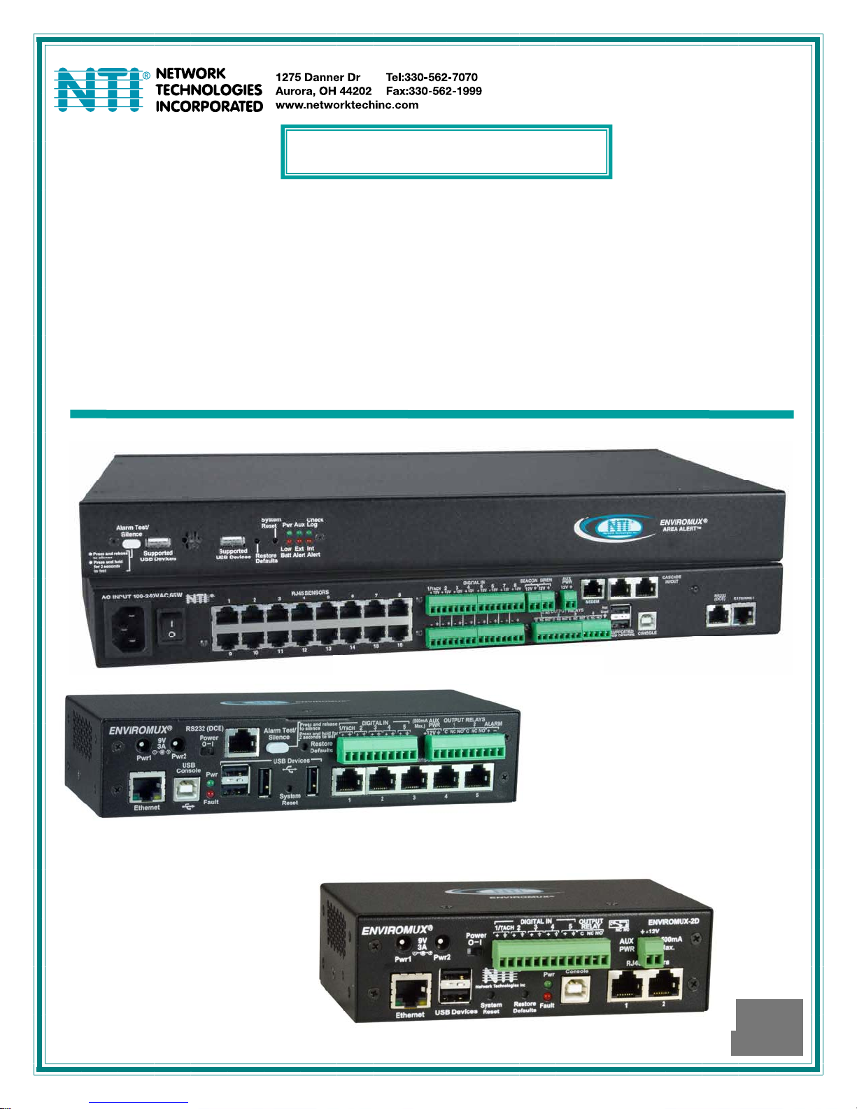
Front and Rear View of ENVIROMUX-16D
Front View of ENVIROMUX-5D
Front View of ENVIROMUX-2D
MAN154 Rev Date 1/30/2014
Page 2
TRADEMARK
ENVIROMUX is a registered trademark of Network Technologies Inc in the U.S. and other countries.
COPYRIGHT
Copyright © 2005, 2014 by Network Technologies Inc. All rights reserved. No part of this publication may be reproduced, stored
in a retrieval system, or transmitted, in any form or by any means, electronic, mechanical, photocopying, recording, or otherwise,
without the prior written consent of Network Technologies Inc, 1275 Danner Drive, Aurora, Ohio 44202.
CHANGES
The material in this guide is for information only and is subject to change without notice. Network Technologies Inc reserves the
right to make changes in the product design without reservation and without notification to its users.
CE Statement
We, Network Technologies Inc, declare under our sole responsibility that the ENVIROMUX-16D , ENVIROMUX-5D and
ENVIROMUX-2D are in conformity with European Standard EN55022.
Firmware Version
Current Firmware version 2.14
The ENVIROMUX-16D contains a sealed lead acid battery. Battery maintenance must be performed by an authorized
trained technician. Always follow local laws and regulations regarding the disposal of this unit.
WARNING
Pb
Pb
RISK OF ELECTRIC SHOCK
maintenance must be performed by authorized service personnel only.
Turn OFF power to the ENVIROMUX and discharge your body’s static electric charge by touching a grounded surface or
use a grounding wrist strap before performing any connections to the unit.
For continued protection against fire and electric shock this device should only be connected to an AC mains outlet
equipped with a proper ground terminal.
CAUTION
. Do not remove cover. No user serviceable components inside. All repairs and
CAUTION
CAUTION
i
Page 3

TABLE OF CONTENTS
Introduction......................................................................................................................................................................1
Materials..........................................................................................................................................................................3
Supported Web Browsers ...............................................................................................................................................4
Features And Functions..................................................................................................................................................5
Installation .......................................................................................................................................................................7
Mounting Instructions-16D...........................................................................................................................................7
Mounting Instructions-5D / -2D....................................................................................................................................8
Sensor Attachment......................................................................................................................................................9
RJ45 Sensor Ports....................................................................................................................................................9
Digital In Terminals.................................................................................................................................................10
Liquid Detection Sensors........................................................................................................................................10
Alarm(Beacon/Siren) Connections .........................................................................................................................12
Connect Output Devices............................................................................................................................................13
Terminal Connection for RS232................................................................................................................................14
Ethernet Connection for Remote User Control..........................................................................................................15
Modem Connection....................................................................................................................................................16
USB GSM Modem ..................................................................................................................................................16
Serial GSM Modem.................................................................................................................................................18
Power Connection-ENVIROMUX-16D ......................................................................................................................19
Dual Power Option..................................................................................................................................................19
DC Power Option....................................................................................................................................................20
Power Connection- ENVIROMUX-5D/-2D.................................................................................................................20
Remote RS232 Device Control...............................................................................................................................22
Overview - Use And Operation......................................................................................................................................24
Sensors...................................................................................................................................................................24
IP Assignment.........................................................................................................................................................24
User Management ..................................................................................................................................................24
Alerts.......................................................................................................................................................................24
Data and Event Logging.........................................................................................................................................25
Email.......................................................................................................................................................................25
Syslog .....................................................................................................................................................................25
SNMP......................................................................................................................................................................25
Modbus TCP/IP Support.........................................................................................................................................25
External Modem......................................................................................................................................................25
Power-on/Reset Operation.....................................................................................................................................25
Out-of-Box Operation..............................................................................................................................................25
Expandability...........................................................................................................................................................25
Device Discovery Tool...................................................................................................................................................26
Use and Operation via Web Interface...........................................................................................................................27
Log In and Enter Password .......................................................................................................................................27
Monitoring..................................................................................................................................................................28
Summary Page.......................................................................................................................................................28
Power Supplies.......................................................................................................................................................29
Power Supply Alert Configuration...........................................................................................................................29
Internal Sensors......................................................................................................................................................31
ii
Page 4

External Sensors.....................................................................................................................................................31
External Sensor Configuration................................................................................................................................36
Specialized Sensors (for S420MA-24V Current Sensor Configuration only).........................................................40
Contact Sensors .....................................................................................................................................................42
Monitor Output Relay..............................................................................................................................................47
IP Devices...............................................................................................................................................................49
IP Cameras.............................................................................................................................................................53
Administration............................................................................................................................................................54
System Configuration .............................................................................................................................................54
Administration-Enterprise Setup.............................................................................................................................58
Administration-Network Setup................................................................................................................................60
User Configuration..................................................................................................................................................65
Group Names..........................................................................................................................................................69
Security...................................................................................................................................................................70
System Information.................................................................................................................................................73
Administration- Firmware........................................................................................................................................74
Advanced-Cascade Configuration..........................................................................................................................75
Reboot the System .................................................................................................................................................80
Smart Alerts...............................................................................................................................................................81
Log.................................................................................................................................................................................91
View Event Log.......................................................................................................................................................91
View Data Log.........................................................................................................................................................92
Log Settings............................................................................................................................................................93
Support ......................................................................................................................................................................94
Logout........................................................................................................................................................................94
Front Panel Controls and LED Indicators......................................................................................................................95
System Reset Button.................................................................................................................................................95
Alarm Test/Silence Button.........................................................................................................................................96
Restore Defaults Button.............................................................................................................................................96
Battery Backup..............................................................................................................................................................96
ENVIROMUX-16D ..................................................................................................................................................96
ENVIROMUX-5DB / -2DB.......................................................................................................................................96
USB Port........................................................................................................................................................................97
Serial Control.................................................................................................................................................................97
Modbus TCP/IP Support ...............................................................................................................................................98
Modbus TCP Function Codes Definition ................................................................................................................98
Function Code 01 - Read the state of Output Relays................................................................................................98
Function Code 02 - Read the state of Digital Inputs..................................................................................................99
Function Code 04 - Read Internal/External Sensors floating point values..............................................................100
Write data to force multiple Output Relays Active/Inactive......................................................................................102
How To Setup Email....................................................................................................................................................103
How To Setup SNMP..................................................................................................................................................105
How To Setup Syslog..................................................................................................................................................108
Locating OIDs..............................................................................................................................................................111
ENVIROMUX-16D Specifications ...............................................................................................................................115
Front Panel Interface...............................................................................................................................................115
RJ45 Sensor Inputs.................................................................................................................................................115
Digital Inputs............................................................................................................................................................115
iii
Page 5

Output Relays..........................................................................................................................................................115
Beacon Port & Siren Port.........................................................................................................................................115
USB Device Ports....................................................................................................................................................115
Control Serial Port “RS232”.....................................................................................................................................116
USB-Serial Port “Console”.......................................................................................................................................116
Auxiliary Power Port ................................................................................................................................................116
Ethernet Port............................................................................................................................................................116
Back-Up Battery.......................................................................................................................................................116
General Specifications.............................................................................................................................................116
TCP/IP .....................................................................................................................................................................116
ENVIROMUX-5D Specifications..................................................................................................................................117
User Interface ..........................................................................................................................................................117
RJ45 Sensor Inputs.................................................................................................................................................117
Digital Inputs............................................................................................................................................................117
Output Relays..........................................................................................................................................................117
Alarm Port................................................................................................................................................................117
USB Device Ports....................................................................................................................................................117
USB-Serial Port “Console”.......................................................................................................................................117
Auxiliary Power Port ................................................................................................................................................118
Ethernet Port............................................................................................................................................................118
General Specifications.............................................................................................................................................118
TCP/IP .....................................................................................................................................................................118
Optional Battery.......................................................................................................................................................118
ENVIROMUX-2D Specifications..................................................................................................................................119
User Interface ..........................................................................................................................................................119
RJ45 Sensor Inputs.................................................................................................................................................119
Digital Inputs............................................................................................................................................................119
Output Relays..........................................................................................................................................................119
USB Device Ports....................................................................................................................................................119
USB-Serial Port “Console”.......................................................................................................................................119
Auxiliary Power Port ................................................................................................................................................119
Ethernet Port............................................................................................................................................................120
General Specifications.............................................................................................................................................120
TCP/IP .....................................................................................................................................................................120
Optional Battery.......................................................................................................................................................120
Wiring Methods ...........................................................................................................................................................121
RS485 Sensor Cable...............................................................................................................................................121
Contact Sensor Wiring.............................................................................................................................................121
Troubleshooting...........................................................................................................................................................122
Recycling Information..................................................................................................................................................124
Index............................................................................................................................................................................125
Warranty Information...................................................................................................................................................127
iv
Page 6

TABLE OF FIGURES
Figure 1- Secure rack mount ears to ENVIROMUX-16D...................................................................................................................7
Figure 2- Mount ENVIROMUX in a rack ............................................................................................................................................7
Figure 3- Rotate the tabs for Zero-RU mounting................................................................................................................................8
Figure 4- Sensors connected by cables with RJ45 connectors..........................................................................................................9
Figure 5- Contact sensor wired to RJ45 socket.................................................................................................................................9
Figure 6- DIGITAL IN Terminal Connections...................................................................................................................................10
Figure 7- Secure liquid detection sensor with tape..........................................................................................................................11
Figure 8- Portion of Water Sensor configuration page.....................................................................................................................11
Figure 9- Connect visual and audible external indicators.................................................................................................................12
Figure 10- Install additional devices to output terminals ..................................................................................................................13
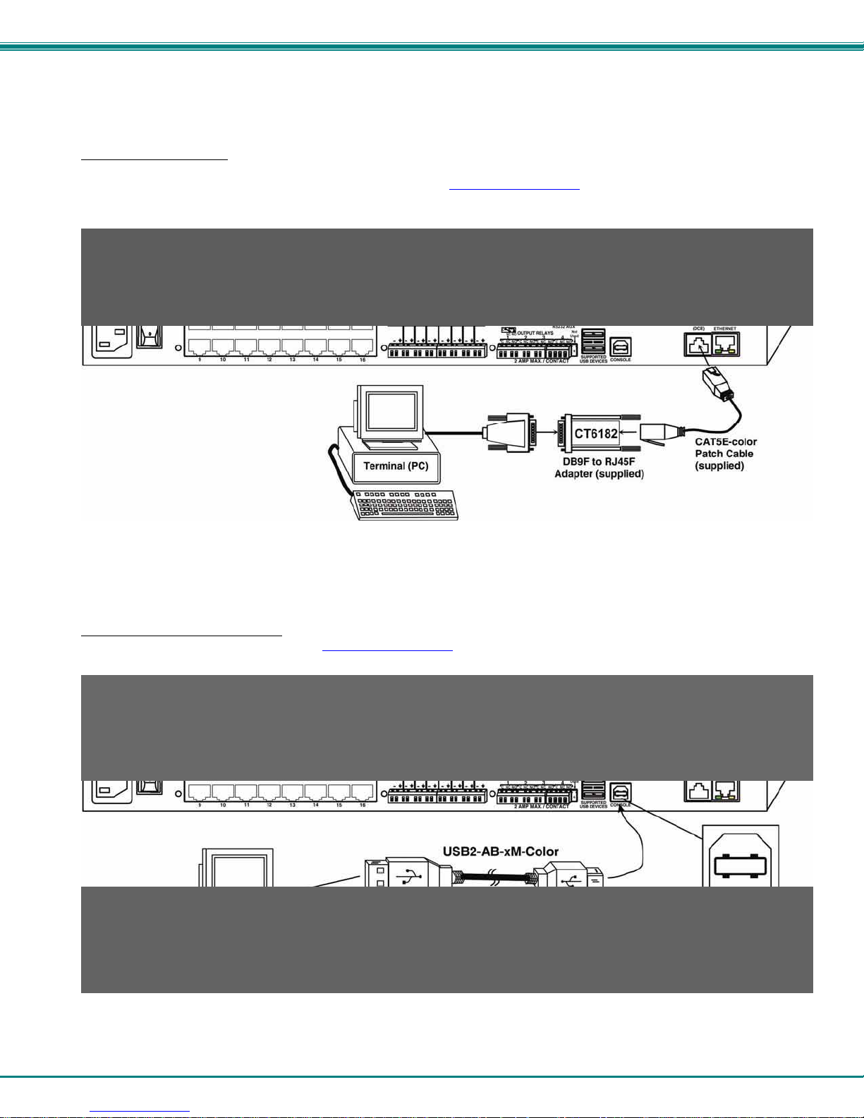
Figure 11- Connect a terminal for direct RS232 serial communication............................................................................................14
Figure 12- Connect a terminal using USB Console port ..................................................................................................................14
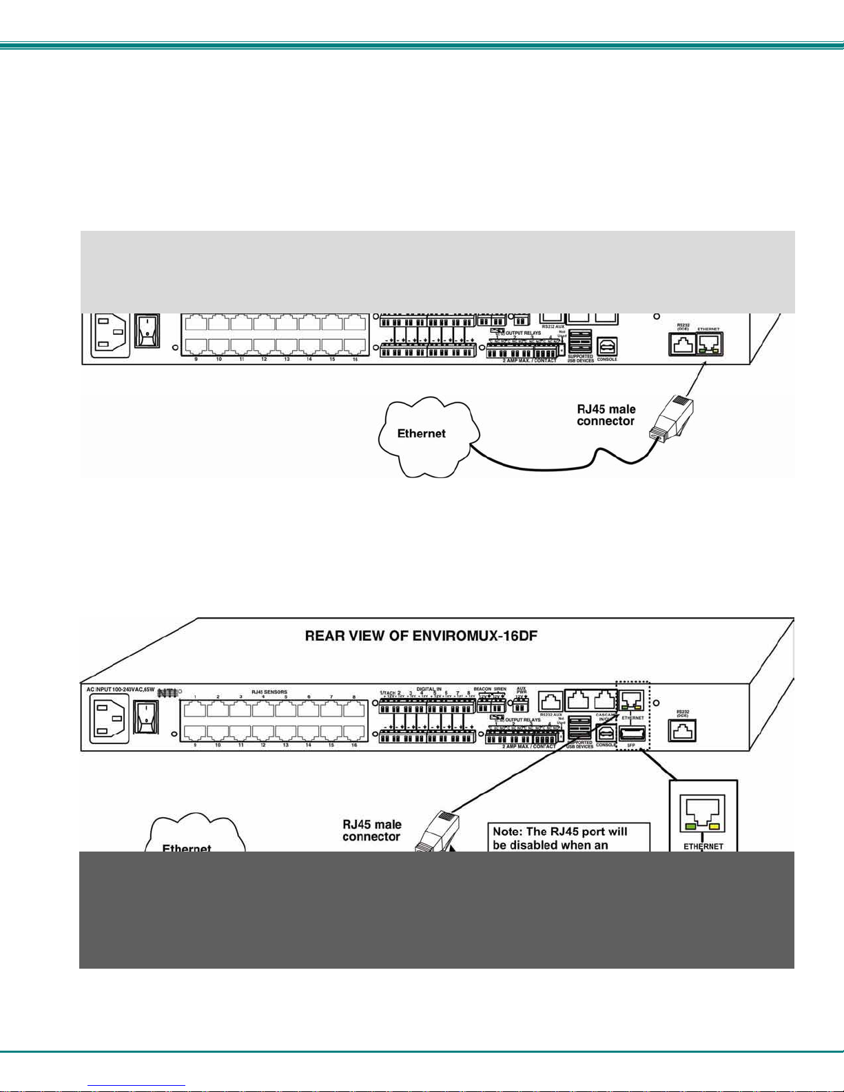
Figure 13- Connect ENVIROMUX to the Ethernet...........................................................................................................................15
Figure 14- Connect ENVIROMUX to Ethernet via SFP....................................................................................................................15
Figure 15- Install USB GSM Modem................................................................................................................................................16
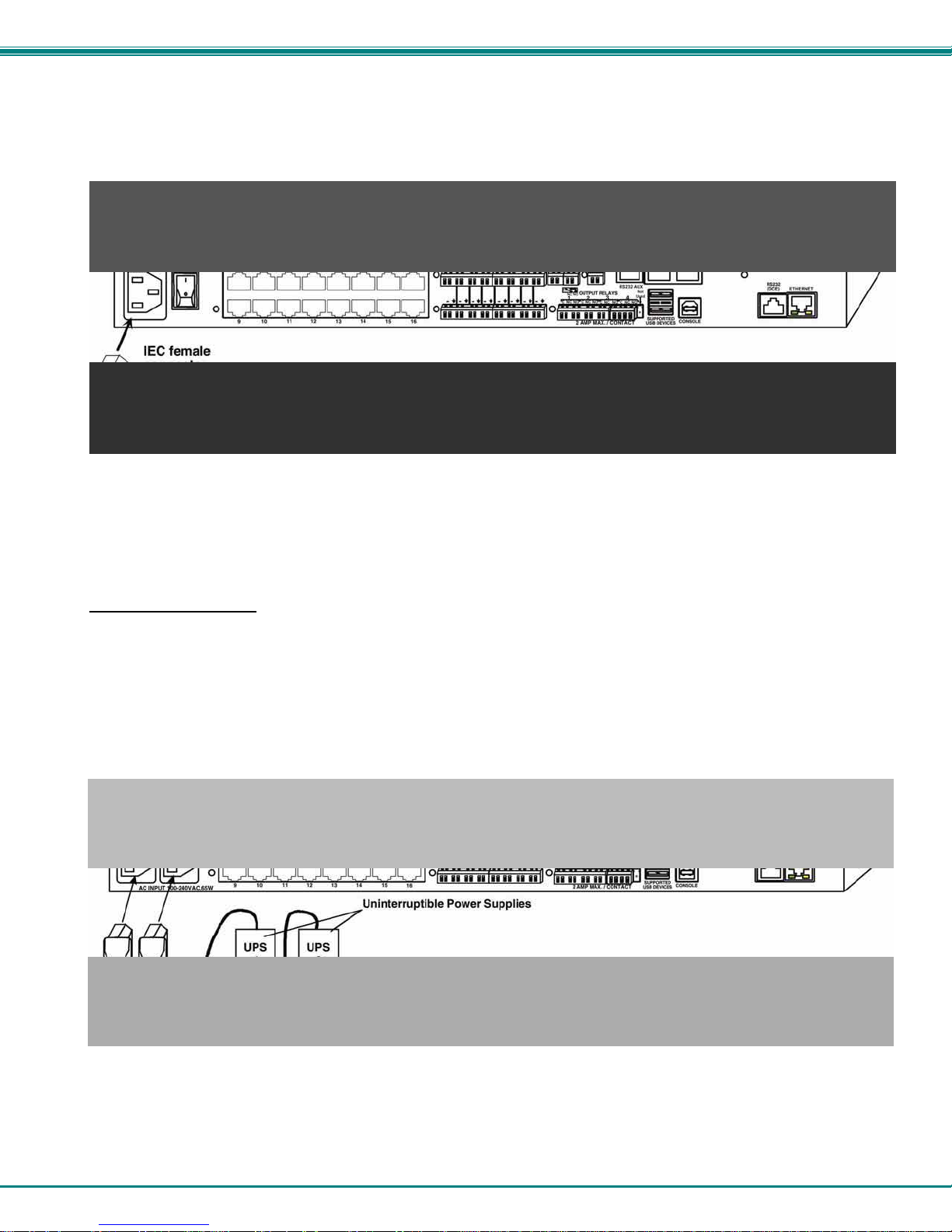
Figure 16- Connect the power cord .................................................................................................................................................19
Figure 17- Power connections for ENVIROMUX with Dual Power Option.......................................................................................19
Figure 18- 48VDC Power Option Connections ................................................................................................................................20
Figure 19- Connect the AC adapter and power-up..........................................................................................................................20
Figure 20- Power connections on ENVIROMUX-5D-48VDP ...........................................................................................................21
Figure 21- Power Supply sensors-Summary Page..........................................................................................................................21
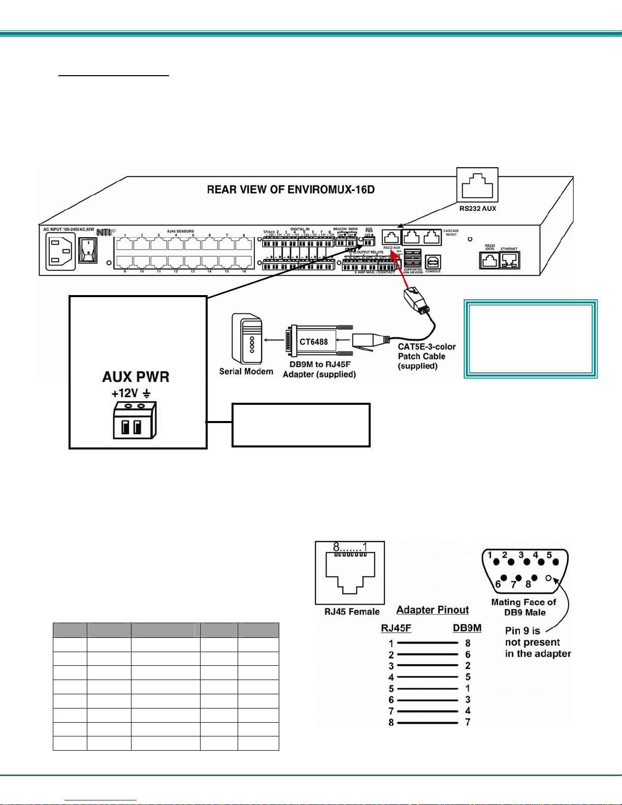
Figure 22- Connect serially controlled device..................................................................................................................................22
Figure 23- Create user "rs232"........................................................................................................................................................22
Figure 24- Connection to serial device successful...........................................................................................................................23
Figure 25- Device Discovery Tool page...........................................................................................................................................26
Figure 26- Login prompt to access web interface............................................................................................................................27
Figure 27- Summary page...............................................................................................................................................................27
Figure 28- Summary Page...............................................................................................................................................................28
Figure 29- Power Supply status- Dual Power model .......................................................................................................................29
Figure 30- Power Supply alerts configuration-part 1........................................................................................................................29
Figure 31- Power Supply alerts configuration-part 2........................................................................................................................30
Figure 32- External Sensor Reading................................................................................................................................................32
Figure 33- Sensor Configuration Page (1).......................................................................................................................................33
Figure 34- Sensor Configuration Page (2).......................................................................................................................................34
Figure 35- Sensor Configuration Page (3).......................................................................................................................................35
Figure 36- Sensor Configuration Page (4).......................................................................................................................................36
Figure 37- Chart to setup alert notification.......................................................................................................................................38
Figure 38- Current sensor added to ENVIROMUX ..........................................................................................................................40
Figure 39- Configuration of sensor connected to ENVIROMUX-S420MA-24V................................................................................40
Figure 40- List of sensors ................................................................................................................................................................42
Figure 41- Add a contact sensor......................................................................................................................................................42
Figure 42- Contact Sensor configuration page ................................................................................................................................43
Figure 43- Digital Input Sensors ......................................................................................................................................................44
Figure 44- Select connector on ENVIROMUX.................................................................................................................................44
Figure 45- Configure New Sensor ...................................................................................................................................................45
Figure 46- Status of Digital Input #2 ................................................................................................................................................45
Figure 47- Open configuration from Digital Input page....................................................................................................................45
Figure 48- Connection that supports Tachometer Sensor ...............................................................................................................46
Figure 49- Monitoring Output Relays...............................................................................................................................................47
Figure 50- Output Relay Status .......................................................................................................................................................47
v
Page 7

Figure 51- Output Relay Contact State............................................................................................................................................47
Figure 52- Configure Output Relay..................................................................................................................................................48
Figure 53- IP Devices monitored .....................................................................................................................................................49
Figure 54- Add new IP Device.........................................................................................................................................................49
Figure 55- IP Device Configuration..................................................................................................................................................50
Figure 56- IP Device Configuration-more.........................................................................................................................................51
Figure 57- Monitoring IP Cameras...................................................................................................................................................53
Figure 58- IP Camera Configuration................................................................................................................................................53
Figure 59- System Configuration page ............................................................................................................................................54
Figure 60- Configuration Backup and Restore.................................................................................................................................55
Figure 61- Select what will be displayed on connected USB LCD Monitor......................................................................................56
Figure 62- Configure the purpose of the "RS232 AUX" port ............................................................................................................56
Figure 63- System Configuration-continued.....................................................................................................................................57
Figure 64- Enterprise Configuration Page........................................................................................................................................58
Figure 65- GSM Modem Status.......................................................................................................................................................59
Figure 66- SMS Relay Configuration ...............................................................................................................................................59
Figure 67- Network Configuration Page...........................................................................................................................................60
Figure 68- Apply IPv4 or IPv6 Settings............................................................................................................................................60
Figure 69- Configure SMTP, SNMP, and security settings..............................................................................................................61
Figure 70- Configure 3G Data Connection.......................................................................................................................................62
Figure 71- Setup SNMP to control output relays..............................................................................................................................64
Figure 72- Usernames List and Status.............................................................................................................................................65
Figure 73- Edit user profile for root user ..........................................................................................................................................65
Figure 74- More user settings..........................................................................................................................................................66
Figure 75-Summary page for User without Admin privileges...........................................................................................................68
Figure 76- Enter custom group names.............................................................................................................................................69
Figure 77- Security Configuration page ...........................................................................................................................................70
Figure 78- Security Configuration- IP Filtering Rules.......................................................................................................................72
Figure 79- System Information page................................................................................................................................................73
Figure 80- Update Firmware Page...................................................................................................................................................74
Figure 81- Cascade configuration options .......................................................................................................................................75
Figure 82- Master with local (RS485) slaves ...................................................................................................................................76
Figure 83- Cascade configuration with Ethernet slaves...................................................................................................................76
Figure 84- Configure which Slaves will be connected to the Master................................................................................................77
Figure 85- Apply alert settings to alert for Slave connection loss.....................................................................................................77
Figure 86- Portion of Summary Page from a Master with a Slave ...................................................................................................79
Figure 87- Reboot System page......................................................................................................................................................80
Figure 88- System is rebooting........................................................................................................................................................80
Figure 89- Events used for Smart Alerts..........................................................................................................................................81
Figure 90- Sensor to be used for a predefined event.......................................................................................................................81
Figure 91- Configuration options for new event...............................................................................................................................82
Figure 92- Event Configuration options continued...........................................................................................................................84
Figure 93- Smart Alert summary page.............................................................................................................................................85
Figure 94- Smart Alert configuration................................................................................................................................................85
Figure 95- Smart Alert configuration- continued ..............................................................................................................................86
Figure 96- Smart Alert Configuration- continued..............................................................................................................................88
Figure 97- Event Logical Function Diagram.....................................................................................................................................89
Figure 98- Examples of Smart Alert conditions................................................................................................................................90
Figure 99- Event Log page ..............................................................................................................................................................91
Figure 100- Data Log page..............................................................................................................................................................92
Figure 101- Log Settings page.........................................................................................................................................................93
Figure 102- Support.........................................................................................................................................................................94
vi
Page 8

Figure 103- Logout ..........................................................................................................................................................................94
Figure 104- Front panel ...................................................................................................................................................................95
Figure 105- USB Flash Drive/Modem/LCD Monitor port..................................................................................................................97
Figure 106- Example of configuration for Gmail server..................................................................................................................103
Figure 107- Configure user to receive alerts via email...................................................................................................................104
Figure 108- SNMP Settings under Network Settings.....................................................................................................................105
Figure 109- Enter at least one group number to sensor configuration...........................................................................................105
Figure 110- Enable SNMP Traps for the sensor............................................................................................................................106
Figure 111- User Settings required for SNMP Traps.....................................................................................................................106
Figure 112- Username must match SNMP configuration ...............................................................................................................107
Figure 113- Apply applicable authentication settings.....................................................................................................................107
Figure 114- Configure which group(s) a sensor will belong to .......................................................................................................108
Figure 115- Enable Syslog alerts for the sensor............................................................................................................................108
Figure 116- Configure user to receive alerts via Syslog ................................................................................................................109
Figure 117- Configure sensor readings to be added to data log....................................................................................................110
Figure 118- Configure data logs to send Syslog messages...........................................................................................................110
vii
Page 9

NTI ENTERPRISE ENVIRONMENT MONITORING SYSTEM
INTRODUCTION
The ENVIROMUX Enterprise Environment Monitoring System (ENVIROMUX) provides a way to supervise, from a remote
location, the environmental conditions and security in cabinets and rooms containing servers, hubs, switches and other network
components. Input data is filtered, collected, analyzed and processed to instantly and accurately display the status of the room.
The user is able to specify parameters for all monitored conditions: if the parameters are exceeded, the unit will signal an alarm,
which may include several pre-defined processes.
The ENVIROMUX-16D, our most feature-filled model, includes sensors that monitor the internal temperature and
humidity of the unit, giving readings that can be used as an estimate for the conditions of other nearby rack components.
All models are capable of monitoring external RS485 sensors and additional digital contact-type sensors (often called opencollector, contact-closure, relay-style, normal-open, or normal-closed). All sensors are sold separately, available from NTI.
ENVIROMUX includes output relays to control devices such as door locks, keypads, and circulation fans. The ENVIROMUX-16D
and ENVIROMUX-5D also include outputs specifically for the connection of an alarm siren and/or beacon.
The external sensors sold by NTI will monitor temperature and humidity, monitor AC line voltage, frequency, and current,
detect smoke, and much more. The temperature and humidity sensors will provide current readings as well as alerts when
thresholds are exceeded. The AC line monitor detects AC line input voltages between 50~250V AC, the Frequency (Hertz)
between 47~63Hz, and the Power (Current) up to 12 amperes from a single AC line. The remainder of the sensors will simply
provide alerts. These sensors can be manufactured by any third party, provided the al ert notification method is compatible. Each
of the aforementioned NTI sensors will connect to the ENVIROMUX via RJ45 connectors and CAT5 cable.
The ENVIROMUX can also work with both 4-wire and 2-wire contact-style sensors (4-wire sensors require a power
connection, 2-wire do not). An external power supply for some 4-wire sensors may be required (sold separately). Screw
terminals are provided for the connection of external contact-style sensors.
The Ethernet provides the main user interface for the ENVIROMUX. The ENVIROMUX provides data logging that can
be viewed via a web browser and send alerts via email, Syslog, SNMP traps, SMS text messages and front panel LEDs. USB
ports are provided for the connection of a USB modem and for downloading log data to a USB flash drive.
Features: (see Feature Differences chart on next page for more details)
• Enables up to 16 users to monitor environmental conditions and security status remotely
• Alerts users of environmental faults via email, Syslog, SMS messages, SNMP traps (v1, v2c, and/or v3), Illuminated
front panel LEDs, or notifications on a web page
• Sensors are assigned to organized groups, and users can receive alerts from any group( s)
• Smart alerts provide sophisticated configurable multi-event triggering of alert messages or device control
• Up to 16 users can control simultaneously via Ethernet and a single user control serially via connected terminal
• Connections include RJ45 and USB for local serial control
• RJ45 w/ LEDs for Ethernet-based control
• Easy connections for sensors and devices
• RJ45 connections w/o LEDs provided for sensors
• Screw terminals for digital input devices
• Screw terminals for digital output devices
• 12VDC provided for all digital inputs (ENVIROMUX-16D only)
• RJ45 Sensors include Temperature, Humidity, Temperature and Humidity, Water, Vibration, Smoke, Motion Sensor,
Glass break detector and many more
• Provides control for devices such as door locks, keypad, or a circulation fan via digital outputs (1A / 30 VDC, .5A /
100VAC)
• Full configuration via web-based graphic user interface
• Limited configuration using text menus via Telnet , SSH, RS232 or USB-to-serial interface
• Browser independent (IE, Netscape, Mozilla, Opera)
• Outgoing mail using SMTP or SMTP over SSL for alert notifications- up to 16 different email addresses
• Configurable Alarms to match specific user schedule
• Local Authentication, SSL3
• Data logging to keep viewable record of events such as changes in the environment or user access
• Monitors (ping) up to 64 configurable IP addresses. Response Timeout and number of retries are user configurable
for each address
• Flash firmware upgradeable via FTP server or web page
• Internal temperature, humidity, and power sensors (ENVIROMUX-16D, 5DB, 2DB (see chart on next page)
• USB ports for USB modem and USB flash drive
1
Page 10

NTI ENTERPRISE ENVIRONMENT MONITORING SYSTEM
The ENVIROMUX-5D Medium Enterprise Environment Monitoring System and ENVIROMUX-2D Small Enterprise
Environment Monitoring System have almost the same functionality as the ENVIROMUX-16D, just fewer connection points.
ENVIROMUX-16D vs. ENVIROMUX-5D vs. ENVIROMUX-2D
Feature Differences
Feature ENVIROMUX-16D ENVIROMUX-5D ENVIROMUX-2D
Internal Sensors
Temperature
Humidity
Battery
RJ45 Sensor Ports
Digital Inputs
12VDC provided on Digital
Inputs
Output Relays
Auxiliary (12V) Power
Terminal
Alerts
Alarm Silence/Test Button
Control Methods
USB Ports for Modem and
Data Logging
Front Panel LEDs
Backup Battery
• 110 or 220 VAC at 50 or 60
Power
* No dedicated alarm beacon/siren terminals although they CAN be connected to ENVIROMUX-2D
** ENVIROMUX-5D / -2D do not include an RS232 port for console control, but a USB Type B “Console” port (and
drivers) is provided for this control method.
Hz via IEC connector. 65W
• Options: dual power, 24VDC,
24VDC dual power, 48VDC,
48VDC dual power
3
9
9 9
9
16 5 2
8
9
4
9 9 9
8 Methods
9
6 Methods 5 Methods** 5 Methods**
4 4 2
6 2 2
9 (1 Hour)
only for ENVIROMUX-5DB only for ENVIROMUX-2DB
Optional (2 Hour)
(ENVIROMUX-5DB)
110 or 220 VAC at 50 or 60
Hz via AC adapter. 3A
Optional Dual Power
48VDC, 48VDC dual power
N/A= Not Available
Options:
¾ ENVIROMUX-16D
¾ Dual Power – ENVIROMUX with two power connections for optional redundant power source connection (see
page 19) - add “DP” to the model number (i.e. ENVIROMUX-16DDP)
¾ DC Power - to install the ENVIROMUX in a Telecom environment (see page 20). Add “-48V” or “-24V” to the
model number (i.e. ENVIROMUX-16D-48V / -24V)
* For -48V model, converter accepts 36~72VDC (48VDC nominal), positive or negative polarity.
* For -24V model, converter accepts 18~36VDC (24VDC nominal), positive or negative polarity.
* 3-pole screw terminal for connecting 48V / 24V input
¾ SFP Socket- ENVIROMUX with socket for SFP module to provide alternative Ethernet connection method- add
“F” to the model number (i.e. ENVIROMUX-16DF)
¾ ENVIROMUX-5D /-2D
¾ DIN Rail Mounting- ENVIROMUX-5D or -2D can be ordered with a DIN rail mountin g bracket- Add “D” to the
part number (i.e. ENVIROMUX-5D-D)
¾ Battery Backup- ENVIROMUX-5D or -2D can be ordered with battery backup support and DC power
monitoring installed, providing up to 2.3 hours of operation in the event of a power failure- to order, add “B” to
the part number (i.e. ENVIROMUX-5DB)
¾ 48V/24V/12V/9V Power Option- ENVIROMUX-5D-48V can be ordered with power connections for 18-72VDC
(24 or 48VDC nominal) in addition to jacks for 9-12VDC AC adapter connection. For dual 48V connections, just
add “DP” to the model number (i.e. ENVIROMUX-5D-48VDP).
2 0
9
5 5
N/A N/A
2 1
8 Methods 6 Methods
9
110 or 220 VAC at 50 or 60
Hz via AC adapter / 3A
Optional Dual Power
N/A
N/A
N/A
Optional (2 Hour)
(ENVIROMUX-2DB)
2
Page 11

NTI ENTERPRISE ENVIRONMENT MONITORING SYSTEM
MATERIALS
Materials included with the ENVIROMUX-16D kit:
• ENVIROMUX-16D Large Enterprise Environment Monitoring System
• Power Cord- country specific (2 power cords for model ENVIROMUX-16D-DP)
• 1-CB4306 USB2-AB-2M-5T 2 meter USB 2.0 male type A-male type-B transparent cable
• CT6182 DB9 Female-to-RJ45 Female adapter
• CT6488 DB9 Male-to-RJ45 Female adapter
• 2-CB4352 5 foot RJ45-to-RJ45 CAT5 patch cable
• CD containing a pdf of this manual, Quick Start Guide, an SNMP MIB file, and the NTI Discovery Tool
• Rack mount kit
Materials included with the ENVIROMUX-5D kit:
• NTI ENVIROMUX-5D Medium Enterprise Environment Monitoring System
• 1- PS4225 120VAC or 240VAC at 50 or 60Hz-9VDC/3A AC Adapter (excluded in ENVIROMUX-5D-48V(DP))
-OR 1- PS4264 120VAC or 240VAC at 50 or 60Hz-9VDC/5A AC Adapter (ENVIROMUX-5D(B)-IND only)
• 1- Line cord- country specific (excluded in ENVIROMUX-5D-48V(DP))
• 1- CB4306 USB2-AB-2M-5T 2 meter USB 2.0 male type A-male type-B transparent cable
• 1- CT6488 DB9 Male-to-RJ45 Female adapter
• 1- CB4352 5 foot RJ45-to-RJ45 CAT5 patch cable
• CD containing a pdf of this manual, Quick Start Guide, an SNMP MIB file, and the NTI Discovery Tool
Materials included with the ENVIROMUX-2D kit:
• NTI ENVIROMUX-2D Small Enterprise Environment Monitoring System
• 1- PS4225 120VAC or 240VAC at 50 or 60Hz-9VDC/3A AC Adapter
• 1- Line cord- country specific
• 1- CB4306 USB2-AB-2M-5T 2 meter USB 2.0 male type A-male type-B transparent cable
• CD containing a pdf of this manual, Quick Start Guide, an SNMP MIB file, and the NTI Discovery Tool
Materials required for connection but not supplied:
• Cables required for connection:
Cat5 for RS485 sensors with RJ45 connectors wired to the TIA/EIA-568B standard (see page 121 for
specifications)
ENVIROMUX-2W-xx 2-wire sensor cables for dry contact sensors
• Cable required for Ethernet connection:
Cat5 cable with RJ45 connectors wired straight through (pin 1 to pin 1, pin 2 to pin 2, etc..)
• ENVIROMUX-TRMPLG Terminating Plug- one required if multiple ENVIROMUX-16D units will be cascaded using
the RS485 connection method (page 75)
See our webpage for the latest sensors available; http://www.networktechinc.com/environment-monitor-16d.html
Contact your nearest NTI distributor or NTI directly for all of your cable needs at 800-RGB-TECH (800-742-8324) in US & Canada
or 330-562-7070 (Worldwide) or at our website at www.networktechinc.com
and we will be happy to be of assistance.
3
Page 12

NTI ENTERPRISE ENVIRONMENT MONITORING SYSTEM
SUPPORTED WEB BROWSERS
Most modern web browsers should be supported. The following browsers have been tested:
• Microsoft Internet Explorer 6.0 or higher
• Netscape 7.2 or higher
• Mozilla FireFox 1.5 or higher
• Opera 9.0
• Google Chrome
4
Page 13

NTI ENTERPRISE ENVIRONMENT MONITORING SYSTEM
A
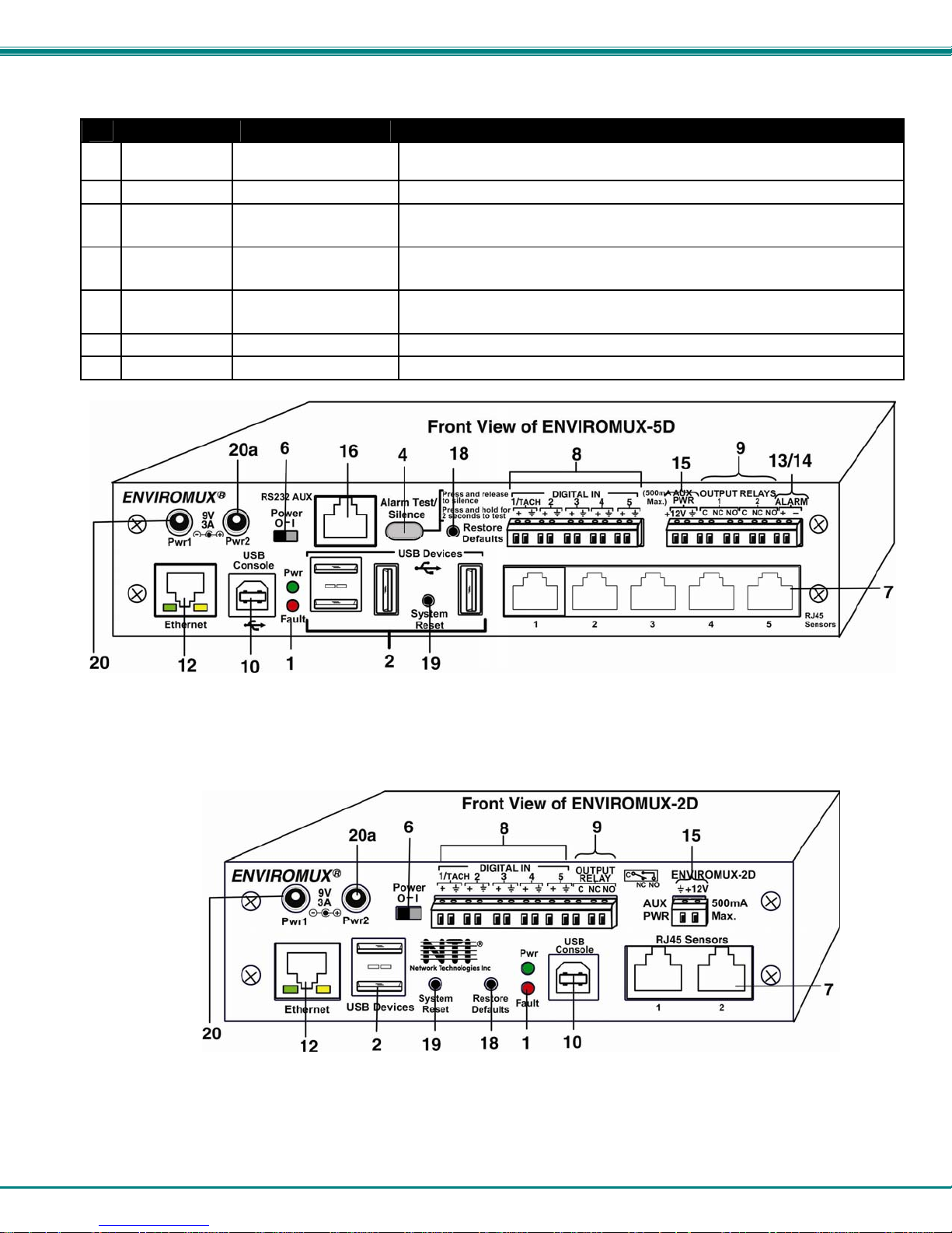
FEATURES AND FUNCTIONS
#
LABEL (LEDs) DESCRIPTION
1
See LED Status Chart (page 95) for more on LED indicators.
#
LABEL CONNECTOR DESCRIPTION
Supported
2
USB Devices
None None Opening for humidity sensor to sense
3
Alarm
4
Test/Silence
--- IEC Connector for connecting the power cable (see also “Dual Power Option” on page 19)
5
--- Power Switch used to turn the power to the ENVIROMUX ON/OFF
6
RJ45 Sensors RJ45 female connectors for attachment of various sensors
7
Digital IN Terminal block connectio n blo ck for wired sensors (2-to-4 wire)
8
Output Relays Terminal block connection block for devices to be controlled in the event of alerts
9
Console USB Type B female
10
RS232 (DCE) RJ45 female connector
11
Ethernet RJ45 female connectors for connection to a Local Area Network (LAN) for remote configuration,
12
Beacon Terminal block for two-wire connection of visual indication of alarm (page 12)
13
Siren Terminal block for two-wire connections of audible indication of alarm (page 12)
14
Pwr- indicates when power to ENVIROMUX is ON (solid ON) and when power failure has
occurred (battery power is ON- LED is blinking once per second)
Low Batt- indicates that the backup battery is running low on power, disconnected, or in failure
Check Log- illuminates when a new entry that is not an alert is added to the log
Int Alert- illuminates when an internal sensor generates an alert
Ext Alert- illuminates when an external sensor generates an alert
Aux- Not used as of this printing
Fault-
red — illuminates if a sensor goes out of range of a configurable threshold
(ENVIROMUX-5D Only)
USB Type A Female for connection of supported USB 1.1 compatible devices (USB modem or flash
drive for logging data)(see more information on pages 16 and 97)
Button Used to test or silence the alarm connected to the siren terminals
For connecting USB cable for serial connection of a terminal to control the
connector
system
lternative port for RS232 serial connection of a terminal to control the system
monitoring, and control
5
Page 14
NTI ENTERPRISE ENVIRONMENT MONITORING SYSTEM
#
LABEL CONNECTOR DESCRIPTION
Aux Pwr Terminal block for powering an auxiliary d evice with 12VDC power at 150mA maximum (fuse
15
protected)
RS232 AUX RJ45 female for connection of a serial modem or remote RS232 device to be controlled
16
Cascade
17
In / Out
Restore
18
Defaults
System Reset Reset Button for manually resetting the system (rebooting) the ENVIROMUX
19
9V 3A- PWR1 2.1x5.5mm Power Jack for connection of primary power supply
20
9V 3A- PWR2 2.1x5.5mm Power Jack for connection of backup power supply
20a
RJ45 female
connectors
Reset Button for manually restoring the ENVIROMUX back to factory settings
used for RS485 method of cascading multiple ENVIROMUX-16D units
(see page 95 for details)
(see page 95 for details)
6
Page 15
NTI ENTERPRISE ENVIRONMENT MONITORING SYSTEM
INSTALLATION
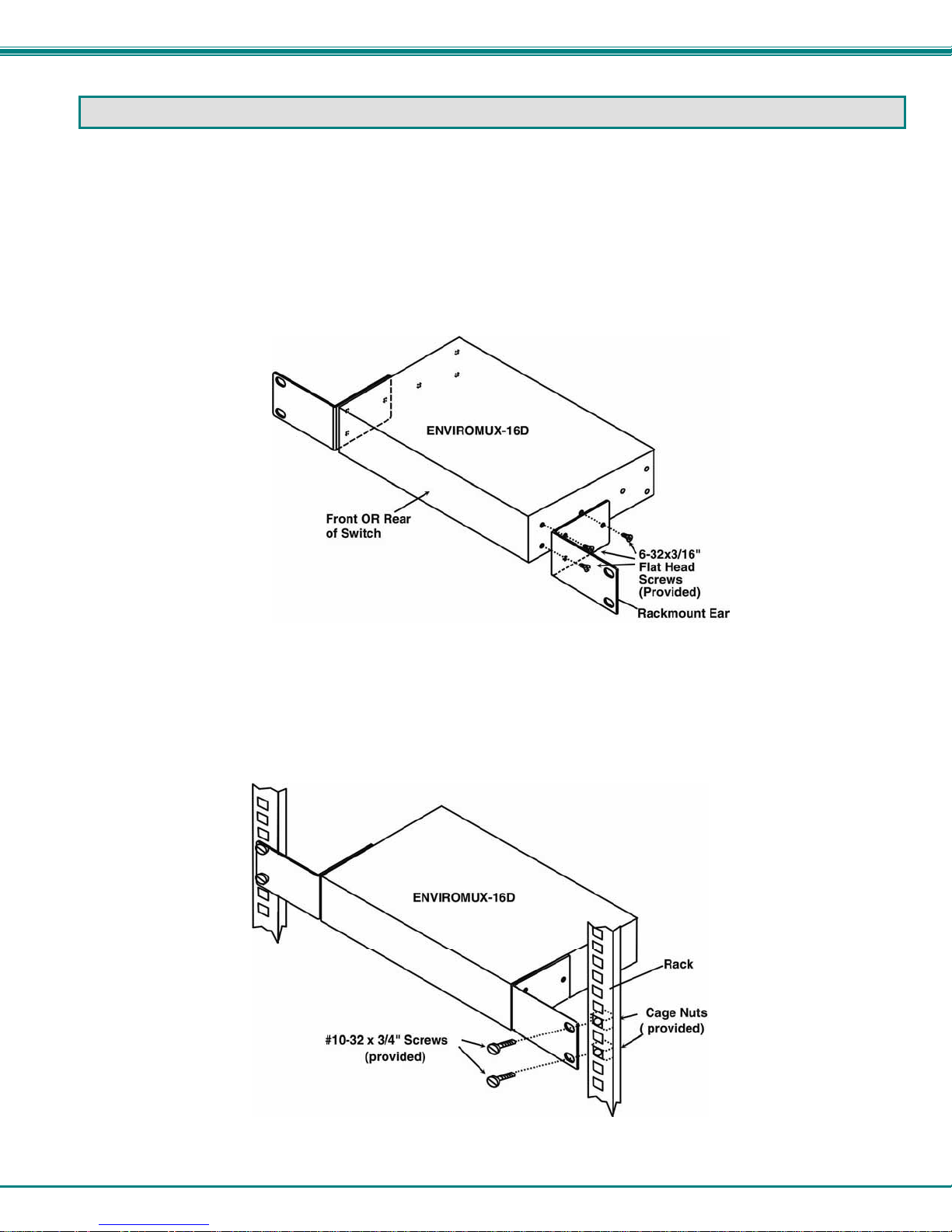
Mounting Instructions-16D
The ENVIROMUX-16D was designed to either sit on a shelf or be mounted in a rack. For mounting in a rack It includes a rack
mount kit to make attachment easy.
1. Attach the ears to the ENVIROMUX using the #6-32x3/16" flat Phillips-head screws (6) provided as shown in the
illustration below.
FYI: The same hole pattern is provided at the front and rear of the ENVIROMUX, enabling the ENVIROMUX to be
mounted with the front facing out or rear facing out.
2. The holes in the ears should line up with pre-threaded holes in the sides of the ENVIROMUX. Tighten the screws
securely.
Figure 1- Secure rack mount ears to ENVIROMUX-16D
3. Install 4 cage nuts to the rack in locations that line up with the holes in the mounting ears on the ENVIROMUX.
4. Secure the ENVIROMUX to the rack using four #10-32x3/4” screws and cage nuts (provided). Be sure to tighten all
Note: Do not block power supply vents in the ENVIROMUX case. Be sure to enable adequate airflow in front of and
behind the ENVIROMUX.
mounting screws securely.
Figure 2- Mount ENVIROMUX in a rack
5. Attach all cables securely to the ENVIROMUX and where necessary supply adequate means of strain relief for
cables.
7
Page 16

NTI ENTERPRISE ENVIRONMENT MONITORING SYSTEM
Mounting Instructions-5D / -2D
The ENVIROMUX-5D and -2D can either be placed on a solid surface, mounted to a wall, or mounted to an accessible surface
within rack (Zero-RU). To mount to a wall or other surface, first remove the screws holding the mounting tabs to the rear of the
box. Rotate the tabs such that they extend from the back of the box, and attach the tabs with the screws removed. Now the
ENVIROMUX can be secured to any convenient surface. Use appropriate hardware (not supplied) when mounting.
Figure 3- Rotate the tabs for Zero-RU mounting
If rack-mounting is preferred, the ENVIROMUX-RK1-5D or ENVIROMUX-RK1-2D rack-mount kit can be used (sold separately).
Simply attach the ears (instructions included with the kit) and secure to a rack with the hardware provided.
FYI: Two sets of mounting holes are provided on the side of the ENVIROMUX to enable the ears to be attached su ch that
the ENVIROMUX can be mounted with the front facing out or rear facing out, as desired.
8
Page 17
NTI ENTERPRISE ENVIRONMENT MONITORING SYSTEM
Sensor Attachment
Connect the desired sensors (sold separately) to the available ports on the ENVIROMUX. Sensors come with one of two
connection methods, RJ45 and individual wires for terminal connection. This section explains both methods of connection.
Configuration of these sensors will come later in this
manual.
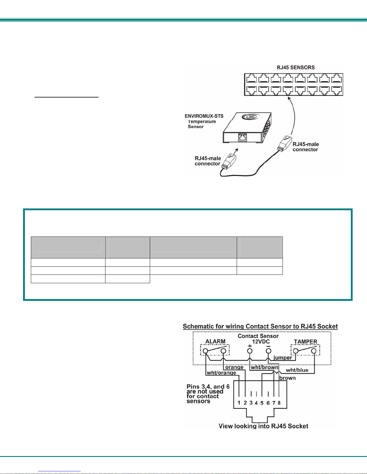
RJ45 Sensor Ports
1. Connect each external sensor having an RJ45 male
connector on it (ENVIROMUX-STS, ENVIROMUXSHS, ENVIROMUX-STHS, ENVIROMUX-LDS) to one
of the female connectors labeled "RJ45 Sensors" on
the ENVIROMUX. Male connectors should snap into
place. Cables may be up to 1000 feet in length. See
page 121 for wiring specification and pinout.
Note: It is very important to locate the temperature
and/or humidity sensors away from ventilation sources
and fans.
Figure 4- Sensors connected by cables with RJ45 connectors
The RJ45 SENSORS ports can be used to connect a variety of sensors. Specifically on the ENVIROMUX-16D, the combined
power load of all 12VDC sensors on each row of ports (ports 1-8 is one row and ports 9-16 is the second) cannot exceed 500mA
per row. Some sensors use more power than others. The table below provides the top power users:
12VDC Power
Sensor
ENVIROMUX-S420MA 120 ENVIROMUX-ACLM-V 70
ENVIROMUX-S420MA-24V 130 ENVIROMUX-S5VDC(-5V) 100
ENVIROMUX-ACLM-P 100
Caution: Be careful not to overload the ENVIROMUX-16D as failure may occur and damage to the ENVIROMUX may
result.
2. Some sensors do not have RJ45 connectors on them
and instead have terminal blocks. These can either be
connected to the "DIGITAL IN" connectors or they can
be terminated and plugged into the remaining RJ45
connectors (see figure-right ). (The illustration uses
CAT5 patch cable to make cable connection easy.)
Some examples of these sensors include ENVIROMUXIMD, ENVIROMUX-IMD-CM, ENVIROMUX-VSS,
ENVIROMUX-SDS, and ENVIROMUX-GBS. Cables
may be up to 1000 feet in length.
Note: For sensors requiring 5VDC power source,
connect the wht/brown wire to pin 4 instead of pin 7.
Consumption
in mA
Sensor
12VDC Power
Consumption
in mA
Figure 5- Contact sensor wired to RJ45 socket
9
Page 18

NTI ENTERPRISE ENVIRONMENT MONITORING SYSTEM
Digital In Terminals
To connect contact sensors without using RJ45 connectors, terminal blocks have been provided labeled "DIGITAL IN". Two
wire switch-only type sensors can be connected to the DIGITAL IN terminals as shown below. If the sensors require a 12V
power source to operate, additional 12V and ground terminals have been provided on each model, with restrictions as shown.
Connect each two-wire or four-wire contact sensor using 16-26 AWG wire.
FYI: The terminal block is removable for easy sensor wire attachment if needed.
NOTE: If used, the ENVIROMUXEDR-SF\ENVIROMUX-EDR-SCR
Electric Strike should be
connected to DIGITAL IN
terminal 8 for power.
Figure 6- DIGITAL IN Terminal Connections
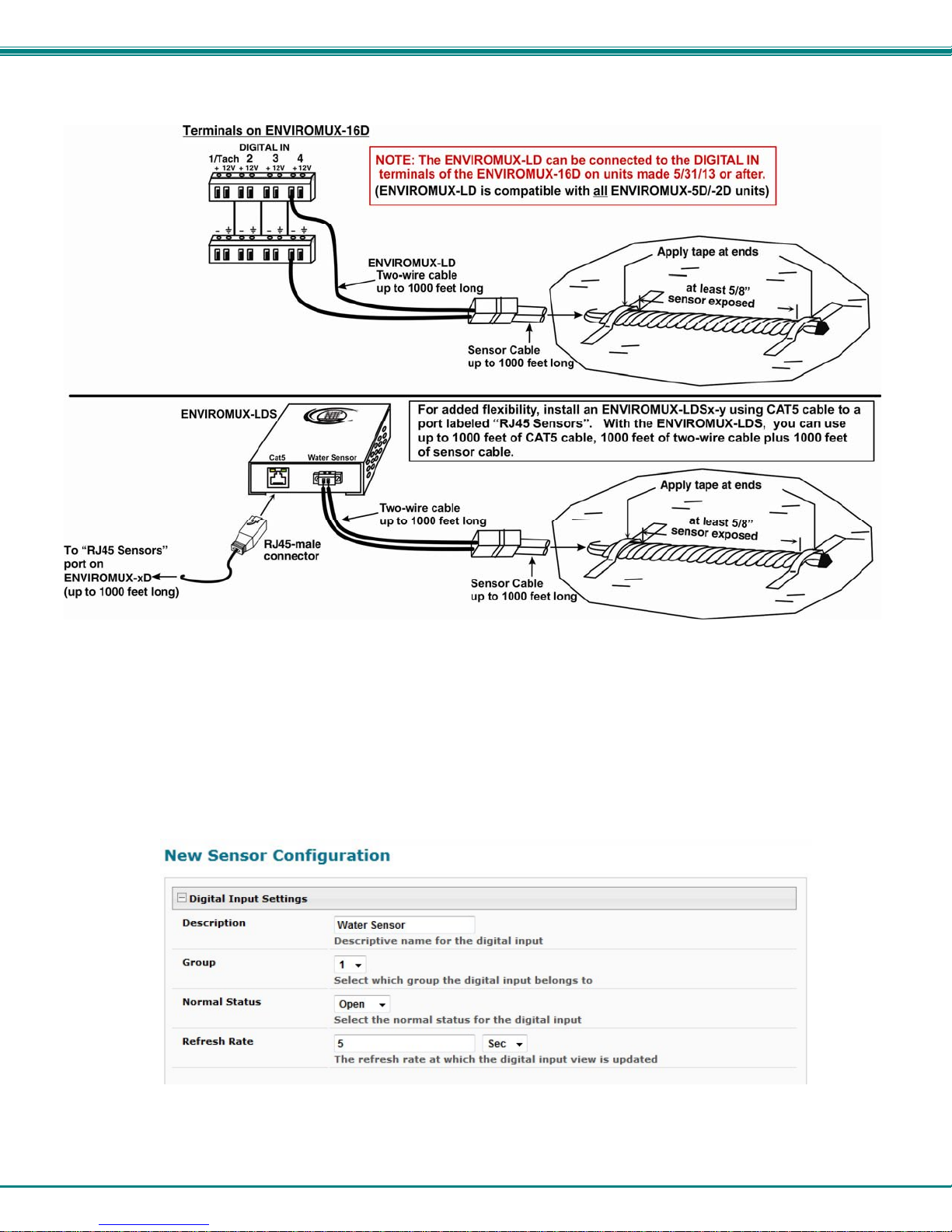
Liquid Detection Sensors
Liquid Detection Sensors are available for simple connection to either the “Digital In” terminals (use model ENVIROMUX-LD) or
the “RJ45 Sensor” ports (use model ENVIROMUX-LDS).
Connect the two-wire cable (up to 1000 feet long) from a liquid detection sensor (ENVIROMUX-LD shown in Figure 7-upper
image) to a set of “DIGITAL IN” contacts.
7-lower image) and connect to an “RJ45 Sensor” port.
The twisted orange sensing cable should be placed flat on the surface (usually the floor) where liquid detection is desired. If tape
is required to hold the sensor in place, be sure to only apply tape to the ends, exposing as much of the sensor as possible. At
least 5/8" of the sensor must be exposed for it to function. (See Figure 7)
For added range (up to 1000 more feet), use an ENVIROMUX-LDS (shown in Figure
10
Page 19
NTI ENTERPRISE ENVIRONMENT MONITORING SYSTEM
Figure 7- Secure liquid detection sensor with tape
To test the ENVIROMUX-LD(S);
1. Configure the sensor (page 42). (Normal Status set to “Open”, Sampling Period set to 5 seconds.)
2. Submerge at least ½ inch of the exposed twisted orange wire (not the wrapped end) for up to 30 seconds. Do NOT use
distilled water as water must be conductive.
3. Monitor the sensor (page 28) to see the sensor “Value” change from “Open” (dry) to “Closed” (wet).
4. Dry the exposed area of sensor and the sensor “Value” should change back to “Open” within 30 seconds.
Figure 8- Portion of Water Sensor configuration page
11
Page 20
NTI ENTERPRISE ENVIRONMENT MONITORING SYSTEM
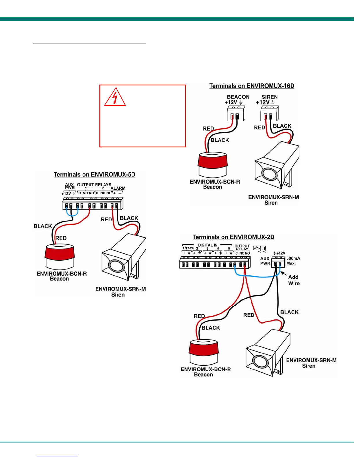
Alarm(Beacon/Siren) Connections
Terminals have been provided for connection of the ENVIROMUX-BCN-R Beacon and ENVIROMUX-SRN-M Siren to use for
visual alerts and audible alerts when configured. Devices such as this can be installed in locations best suited to get
attention. The terminals for these connections will accept 16-26 AWG wire.
WARNING
Devices connected to
either the Beacon or the
Siren terminals cannot
exceed 180mA contact
load.
Note: The maximum combined load that can be
connected to the “AUX PWR” terminals on the
ENVIROMUX-5D / -2D is 500mA. (For the
ENVIROMUX-16D the maximum is 150mA.)
Figure 9- Connect visual and audible external indicators
12
Page 21
NTI ENTERPRISE ENVIRONMENT MONITORING SYSTEM
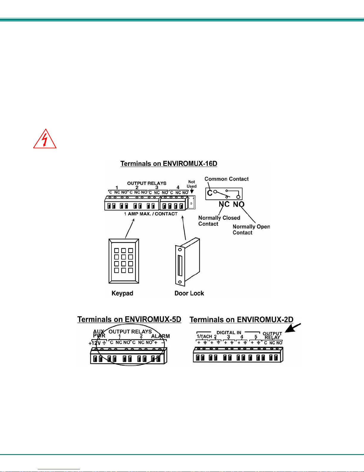
Connect Output Devices
For connection of additional output devices to be controlled by the ENVIROMUX, terminals labeled "Output Relays" have
been provided. The contacts will work as switches to either close or open circuits (switch ON or OFF) when used. The
“default” position of the switch is configurable independently (page 47) and how the switch reacts to sensor alerts can also be
configured on any Sensor Configuration page (page 32).
The status page and any sensor configuration page describe the Output Relay’s status as either “active” or “inactive”.
• When a relay is “active”, the circuit will be closed between the Normally Open and Common contacts of the relay.
• When a relay is “inactive”, the circuit will be closed between the Normally Closed and Common contacts of the
relay.
OUTPUT RELAY dry contact ratings must not be exceeded. Dry contact rating:
WARNING
directly to AC mains wiring.
DC 30V, 1A; AC 100V, 500mA. The OUTPUT RELAY contacts are not to be connected
Figure 10- Install additional devices to output terminals
13
Page 22
NTI ENTERPRISE ENVIRONMENT MONITORING SYSTEM
Terminal Connection for RS232
If control via serial connection is going to be used, serial control can be achieved using the “USB Console” port (all models) or
the “RS232” port (ENVIROMUX-16D only). A terminal connection is accessible by the user “root” only.
To use the “RS232” port
ENVIROMUX. Plug the other end of the CAT5 cable into an RJ45-to-DB9F adapter (supplied), and connect the adapter to the
RS232 port on the control terminal. Follow the instruction in the Serial Control Manual
Control feature.
, connect one end of a CAT5 patch cable (supplied) to the port labeled “RS232” on the rear of the
for configuration and use of the Serial
Figure 11- Connect a terminal for direct RS232 serial communication
To use the USB “CONSOLE” port, connect a USB cable (2 meter cable supplied) between the ENVIROMUX and your PC.
Then install the drivers as described in the Serial Control Manual
.
Figure 12- Connect a terminal using USB Console port
14
Page 23
NTI ENTERPRISE ENVIRONMENT MONITORING SYSTEM
Ethernet Connection for Remote User Control
To make a remote connection, over the Ethernet, from anywhere on the local area network, connect a CAT5/5e/6 Ethernet
cable with RJ45 male connectors on the ends, wired straight through (pin 1 to pin 1, pin 2 to pin 2, etc.). Up to 8 users can
connect to the ENVIROMUX using the Ethernet at a time.
Note: A direct connection from a computer’s Ethernet port to the ENVIROMUX “ETHERNET” port may also be made
using the same cable.
Figure 13- Connect ENVIROMUX to the Ethernet
If you have purchased the ENVIROMUX-16DF (or similar model with SFP option), the unit includes an SFP (Small Formfactor Pluggable) port to use for Ethernet connection. The SFP port supports 100Mbps SFP Transceivers, Cisco compatible.
Only one of the two Ethernet ports can be used at a time. The RJ45 Ethernet port will be disabled when an SFP module is
installed.
Figure 14- Connect ENVIROMUX to Ethernet via SFP
15
Page 24

NTI ENTERPRISE ENVIRONMENT MONITORING SYSTEM
Modem Connection
The ENVIROMUX includes support for a GSM modem to send alert notifications via SMS to a cell phone if desired. Either a USB
GSM modem (all
can receive SMS alert messages directly on their cell phone. When a USB 3G modem is used, SMS alert messages, all email
messages, and web interface control over the ENVIROMUX is possible.
USB GSM Modem
To use a USB GSM Modem, a USB modem (with GSM SIM card configured for SMS messaging) can be connected to one of the
USB ports on the ENVIROMUX. The remaining USB Type A connector(s) on the ENVIROMUX is available for the connection of
a USB Flash Drive for data logging (pages 94 and 97).
Once installed, the ENVIROMUX will sense the modem and provide status information on the “Enterpris e Setup” page in the web
browser (page 58).
The USB GSM modems that have been tested and are confirmed to be compatible with the ENVIROMUX include:
• HiLink E303 3G Modem (NTI # ENVIROMUX-3GU)
• E-Lins M300D Industrial USB Modem
(NTI# ENVIROMUX-3GU-IND)
• Zoom 4595 Modem • Teltonica USB/G10 Modem
models) or a serial GSM modem (ENVIROMUX-16D/-5D only) may be connected. Using a modem each user
• iCON GI1505(M) 3G Modem
• iCON GI0452 3G Modem
Figure 15- Install USB GSM Modem
Cell phone Mini SIM card for GSM modem
A SIM card or Subscriber Identity Module is a portable memory chip used in some models of cellular telephones. It can be thought
of as a mini hard disk that automatically activates the phone (or in this case the GSM modem) into which it is inserted.
SIM cards are available in two standard sizes. The first is the size of a credit card (85.60 mm × 53.98 mm x 0.76 mm). The newer,
more popular miniature-version has a width of 25 mm, a height of 15 mm, and a thickness of 0.76 mm.
Some cellular service providers use Mini SIM cards. Verify with your service provider that their Mini SIM card will work with GSM
/ 3G GSM modems before making a purchase.
Your USB modem can be used for 3 different levels of functionality:
¾ SMS Messaging Only
¾ 3G Data Transfer And SMS Messaging
¾ 3G Data Transfer, SMS Messaging, and Web Interface
SMS Messaging Only
When using your modem only for SMS messaging, make sure the SIM card is for GSM communication (not CDMA), configured to
send SMS messages, and that it is not locked (some SIM cards are "locked" to search for a specific IMEI number of the phone to
operate).
Note: When configured for SMS messaging only, no access to the ENVIROMUX will be possible through the modem.
16
Page 25

NTI ENTERPRISE ENVIRONMENT MONITORING SYSTEM
3G Data Transfer And SMS Messaging
To use your USB modem for 3G Data connection, your SIM card must be configured to support 3G data connections and have
either public or private IP address. Make sure the account associated with the SIM card also has SMS messaging enabled if
this feature will be used. With 3G data connection support, the ENVIROMUX can be configured (page 62) to send all alert
messaging through the USB modem instead of requiring an Ethernet connection for these messages.
Note: When configured for 3G data transfer and SMS messaging only, no access to the ENVIROMUX will be possible
through the modem.
3G Data Transfer, SMS Messaging, and Web Interface
To access the web interface through your USB modem, your SIM card must be configured to support 3G data connections and
have a public IP address. The ENVIROMUX can be configured (page 62) to send all alert messaging through the USB modem
instead of requiring an Ethernet connection for these messages. With a public IP address, you will also be able to access the web
interface using the IP address of the SIM card for full control of the ENVIROMUX through the modem.
Make sure the account associated with the SIM card also has SMS messaging enabled if this feature will be used.
Contact your service provider to obtain a SIM card with the features you desire.
17
Page 26
NTI ENTERPRISE ENVIRONMENT MONITORING SYSTEM
Serial GSM Modem
To use a serial modem (ENVIROMUX-16D/-5D only), connection of the modem to the ENVIROMUX requires a CAT 5 patch cable
and RJ45-to-DB9 male adapter (supplied). The modem connects to the “RS232 AUX” port. The firmware in the ENVIROMUX
must be version 1.3 or later.
Operation and use of the modem will be the same as that of the USB GSM modem. Once installed, the ENVIROMUX will sense
the modem and provide status information on the “Enterprise Setup” page (page 58).
The “AUX PWR” terminals of
the ENVIROMUX-16D may
be used to power the modem
provided the modem does
not require more than 150mA
to operate.
Up to 1000 feet of CAT5E (350Mhz) cable may be used at a baud rate of 115,200bps.
Serial Modems Tested Include:
The AUX PWR terminals on
the ENVIROMUX-5D will
supply up to 500mA.
• Sierra Wireless Airlink MP895
• Four-Faith F1103 (NTI# ENVIROMUX-GSM-IND)
• MultiTech MTCBA-G-F2
• Enfora GSM1308
• Teltonika ModemCOM/G10
CT6488 Adapter
DB9 Male to RJ45 Pin Assignments
RJ45 Signal DB9M Signal
1 RTS Connected to 8 CTS
2 DTS Connected to 6 DSR
3 TxD Connected to 2 RxD
4 GND Connected to 5 GND
5 GND Connected to 1 DCD
6 RxD Connected to 3 TxD
7 DSR Connected to 4 DTR
8 CTS Connected to 7 RTS
The “RS232 AUX” port
can also be used to
control a remote RS232
device. See page 22
for more on this feature.
18
Page 27
NTI ENTERPRISE ENVIRONMENT MONITORING SYSTEM
Power Connection-ENVIROMUX-16D
Connect the power cord supplied to the IEC connector on the rear of ENVIROMUX-16D. Plug the other end into AC mains and
use the switch to power ON ENVIROMUX.
Figure 16- Connect the power cord
Dual Power Option
The ENVIROMUX-16DDP has two IEC connectors on the rear, for connection to two separate power sources. If the power
source connected to “PWR 1” fails, the ENVIROMUX will automatically and without interruption switch over to the power source
connected to “PWR 2” before switching to the battery backup (page 96).
Note: If only one power source is used, it should be connected to “PWR 1”.
Note: The power ON/OFF switch is located on the front panel of ENVIROMUX when two IEC connectors are present.
Figure 17- Power connections for ENVIROMUX with Dual Power Option
19
Page 28
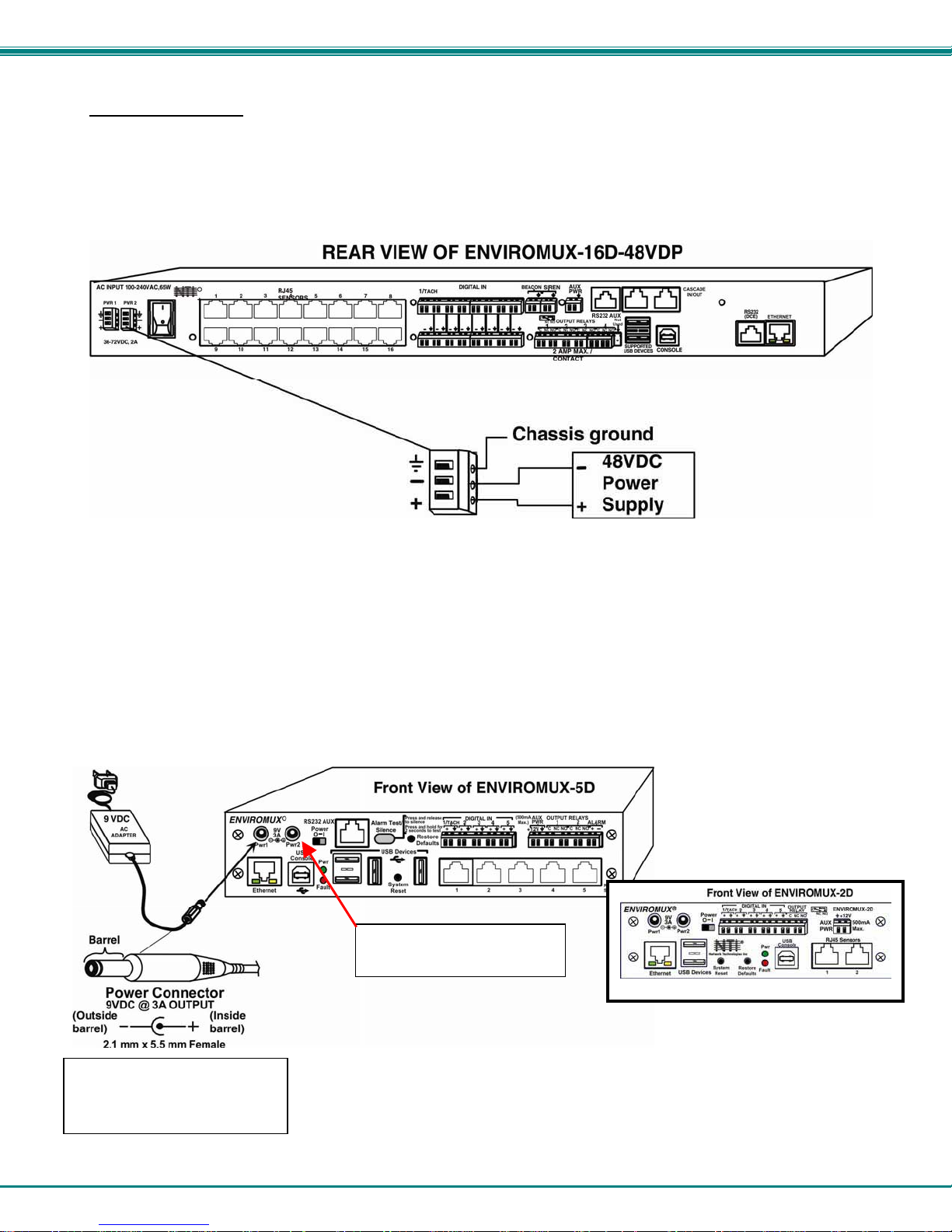
NTI ENTERPRISE ENVIRONMENT MONITORING SYSTEM
DC Power Option
The ENVIROMUX-16D is available with connections for DC power connection. The ENVIROMUX-16D-48V can be connect to a
36~72VDC (48VDC nominal) power supply. The ENVIROMUX-16D-24V can be connected to a 18~36VDC (24VDC nominal)
power supply. Each has connections on the rear for a user-supplied DC power supply. This is typically used when the
ENVIROMUX is installed in a Telecom environment. The ENVIROMUX-16D-xxV will accept a DC power source with positive or
negative polarity. A removable 3-pole screw terminal is provided for easy connection. The image below shows an
ENVIROMUX-16D-48VDP, which has dual 48VDC power connections for a dual power supply opti on (also available for the
24VDC model).
Figure 18- 48VDC Power Option Connections
Power Connection- ENVIROMUX-5D/-2D
Note: Sensors should be connected before supplying power to the ENVIROMUX.
Connect the AC adapter to the connection marked "PWR1" or “PWR2” on the ENVIROMUX and plug it into an outlet. If you have
an alternate source of 9V power for the ENVIROMUX, the second PWR connection is provided to make that source available. If
the source connected to “PWR1” is lost for any reason, the ENVIROMUX will automatically switch to receiving power from the
source connected to “PWR2”.
ENVIROMUX-5D(B)-IND uses
Figure 19- Connect the AC adapter and power-up
a 9VDC 5A power supply with
2.5mm x 5.5mm Female
Port for backup power
source is available for use
20
Page 29
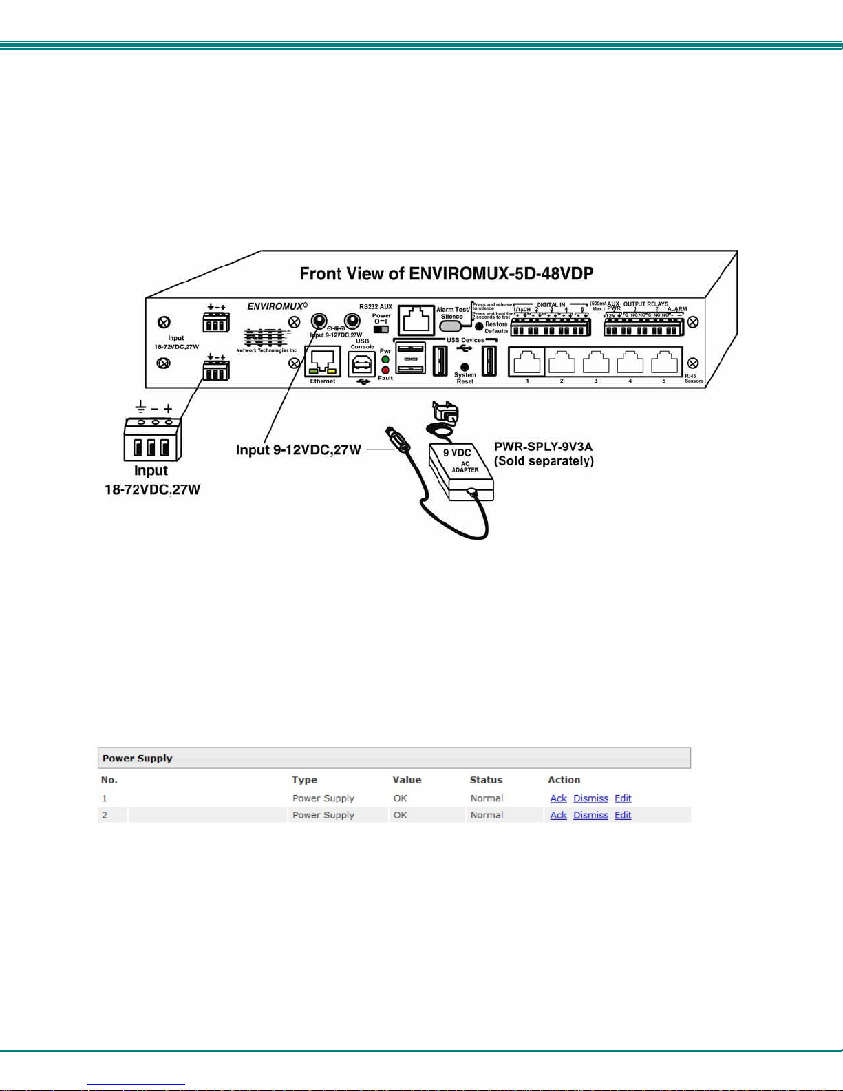
NTI ENTERPRISE ENVIRONMENT MONITORING SYSTEM
The ENVIROMUX-5D-48V is available with connections for a 18~72VDC (24 or 48VDC nominal) user-supplied power supply.
This is typically used when the ENVIROMUX is installed in a Telecom environment. The ENVIROMUX-5D-48V will accept a DC
power source with positive or negative polarity. A removable 3-pole screw terminal is provided for easy connection. The image
below shows an ENVIROMUX-5D-48VDP, which has dual 18-72VDC power connections for a dual power supply option.
For your convenience, the power jacks for connecting and AC adapter are also provided, and may be used as well. These jacks
will accept 9-12VDC (9VDC 3A power supply may be purchased separately-order PWR-SPLY-9V3A). All power con nections can
be used simultaneously without damage to the ENVIROMUX.
Figure 20- Power connections on ENVIROMUX-5D-48VDP
Note: The power supply monitor on the sensor summary page will only display the status of the 18-72VDC connections.
The 9-12VDC power connections will be ignored on the ENVIROMUX-5D-48V(DP) models.
Figure 21- Power Supply sensors-Summary Page
21
Page 30
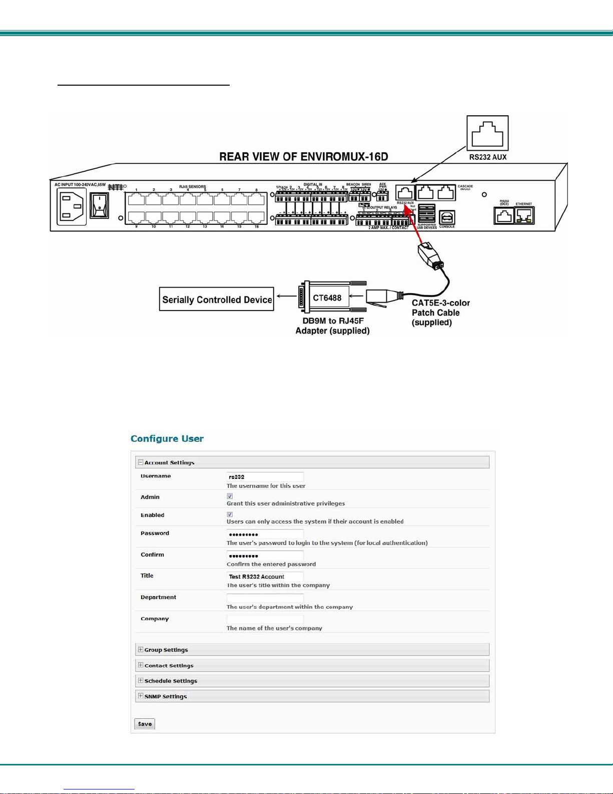
NTI ENTERPRISE ENVIRONMENT MONITORING SYSTEM
Remote RS232 Device Control
The “RS232 AUX” port can be used to connect a remote serially-controlled device. Once connected, a user named “rs232” can
login to the ENVIROMUX from a command prompt and begin sending commands directly to the serial device.
Figure 22- Connect serially controlled device
To control a remote serially-controlled device from the “RS232 AUX” port:
1. Configure the “Auxilliary Serial Port” under System Configuration (page 56) as a Remote Serial Port with the correct
parameters for communication with the device.
2. Setup a user named “rs232” (must be lowercase letters) with password under User Configuration (page 65)
Figure 23- Create user "rs232"
22
Page 31

NTI ENTERPRISE ENVIRONMENT MONITORING SYSTEM
3. Open a SSH client program (Putty, Tera Term, etc.), connect to the ENVIROMUX by entering the IP address of the
ENVIROMUX.
4. When prompted for a login enter “rs232”.
5. When prompted enter the password you have assigned.
With a successful login you will receive the message “Connected to RS232 port”. You are now ready to send commands
directly to the connected serially controlled device.
Figure 24- Connection to serial device successful
To exit the connection, close the command window.
23
Page 32

NTI ENTERPRISE ENVIRONMENT MONITORING SYSTEM
OVERVIEW - USE AND OPERATION
The ENVIROMUX is controlled via RS232 or Ethernet using a terminal emulator, web browser, or SNMP monitor. The
user interfaces are for viewing and configuring sensor data and system settings. However, full configuration of the system can be
done only through the Web browser due to graphics limitations in the other interfaces.
The web interface allows for the configuration of the thresholds for all attached sensors, their alert methods, and the
formats of the alerts. In addition, network information (IP address, subnet mask, default gateway, DNS, etc.), user administrative
settings, and log settings can also be configured. All settings are saved in memory when applied. A user may also restore the
unit back to its default settings at any time via the web interface (see page 55), text menu (see Serial Control Manual
on the front panel (page 96).
Individual sensor status pages are available for each connected sensor. A sensor summary page allows the user to view
the connected sensors’ current values, threshold settings and alert statuses. Also, the user can view recorded sensor readings
that have been stored in the system data log.
) or a button
Sensors
The ENVIROMUX provides RJ45 sensor input jacks and screw terminal ports. Some available sensor configurations
include Temperature, Humidity, or Temperature+Humidity, Liquid, Vibration, Smoke, Motion Sensor, Glassbreak detector, and AC
Line Monitors. See page 2 for more on available sensors.
page 32). Sensor readings can be reported continuously, only when readings change, or at a regular rate (for instance, a
temperature reading could be updated once each hour).
closure / open-collector type that operate on 12VDC and 50mA, with a maximum load resistance of 10kΩ or less. (See page 44
for more info.)
IP Assignment
Initially, IP configuration will be the easiest to change using the NTI Device Discovery Tool (found on the CD), which will
search for NTI devices on the user’s network and allow IP assignment to them through its web interface. Other settings for subnet
mask and default gateway may also be configured (see page 26). These settings must be configured properly in order to access
the ENVIROMUX web interface.
User Management
local password authentication. Each user may be assigned "User" or "Administrative" privileges. Users accessing the
ENVIROMUX will be granted access to only the monitoring functions, and will be able to view the log. An account with
"Administrative" privileges has all of the privileges necessary to view and configure network settings, add /edit/delete other user
accounts, configure sensors, etc..
The temperature/humidity sensors have been given factory default settings and thresholds that can be change d (see
Sensors connected to the terminals labeled "Digital In" must be manually configured, a nd can be any sensor of contact-
An IP address can be assigned to the ENVIROMUX through any of three methods:
• Using the NTI Device Discovery Tool (page 26)
• Through the web interface on the Network page (page 60)
• Using the RS232 interface (Serial Control Manual
The ENVIROMUX supports up to 16 user accounts plus the root account (page 65). Each user account is protected by
)
Alerts
A high and low threshold limit can be set for each temperature or humidity sensor within the operating range of the
sensor. Each open collector/contact-closure sensor can be set as normally-open or normally-closed. When a sensor takes a
reading that is outside a threshold or a contact-closure sensor is not in its normal condition, an alert notification can be generated.
The user can specify how often alert notifications are provided. Also, there is an adjustable alert delay time involved with alert
notifications. This means if a sensor’s readings are moving in and out of the threshold boundaries within a configur able period of
time, additional alert notifications will not be sent. Alerts may be sent if the condition of the sensor returns to normal or back within
its threshold boundaries. Alert notifications (page 39) will be provided through any or a ll of six main methods:
• visible notification via the user interfaces (red LED on front panel, beacon, alert on web page)
• emails (up to 17 different addresses)
• SNMP Traps
• SMS Messages (up to 17 different phone numbers)
• Syslog Messages
• audible notification via siren
24
Page 33

NTI ENTERPRISE ENVIRONMENT MONITORING SYSTEM
Data and Event Logging
The ENVIROMUX can log sensor readings, sensor alerts, alert handling, sensor connections/removals, and us er
logins/logouts. The logs can be viewed at any time through the web interface (page 92). Additionally, as entries are generated,
they can be emailed or sent as SNMP traps. Entries can be deleted from the logs via the web interface. The maximum size of
each log is 1000 entries, listed in chronological order. Each log’s behavior upon reaching this maximum s ize can be configured,
allowing the log to either wrap (overwrite oldest entries), stop logging, or clear and start over. The entire log can be downloaded
as a plain text file from the web interface at any time. Log entries can be removed individually, in groups, or all at once.
Email
The ENVIROMUX can access an outgoing SMTP server (authenticated or non-authenticated, with or without SSL
encryption) to send email. Outgoing mail may contain pre-formatted alert notifications or data log messages (samples on page
92). The user can configure what conditions cause emails to be sent. The ENVIROMUX’s email address can be co nfigured
through the web interface on the Enterprise Setup page (page 58), and SMTP server information can be configured on the
Network Setup page (page 60). Up to 17 outgoing email addresses (112 characters max. including commas) may be configured
(corresponding to the 16 user and 1 root email addresses). An example of email configuration can be found on page 103.
Syslog
The ENVIROMUX can send alerts as SYSLOG messages when a sensor enters/leaves alert mode, and for all log
events. The destination for SYSLOG can be configured in each user profile (page 67). For detailed instructions on setting up
Syslog, see page 108.
SNMP
an SNMP MIB browser, a user can monitor all sensor statuses and system IP settings, as well as configure sensor thresholds,
sensor names, and the system name. Click on the checkbox for SNMP under contacts (page 67) for each user that should
receive SNMP messages. The SNMP agent supports SNMP v1, v2c and v3.
Note: The SNMP MIB file (sems-16-v1.xx.mib), for use with an SNMP MIB browser, can be found on the manual CD.
Click on the link to open the file, then save the file to your hard drive to use with the SNMP MIB browser.
The ENVIROMUX can send alerts as SNMP traps when a sensor enters/leaves alert mode, and for all log events. Using
Modbus TCP/IP Support
The ENVIROMUX is equipped with Modbus TCP/IP support to enable PLC controls to read the value/state of sensors and read
and command the state of relays.
External Modem
An external modem (GSM) can be connected to allow the system to send alert notifications via SMS messages. When a
sensor crosses a threshold, an alert notification can be formatted to SMS message (see page 67) and the modem could transmit
the message to pre-specified cellular numbers (up to 17- one for each user). The external modem can be suppl ied from an
external power supply or from the USB port.
Power-on/Reset Operation
On power-up, after going through its boot sequence, the ENVIROMUX will launch the monitoring application, load any
stored configuration values, and immediately identify and begin taking readings from any connected sensors. Alerts will be
reported using the configured alert methods, and data will be logged using the stored preferences. A user can log in at any time
after the system has launched the monitoring application (approximately 60 seconds after power is applied) to view and configure
properties of the system and its sensors.
FYI: The boot sequence can also be initiated manually using the System Reset button. See page 95 for details.
Out-of-Box Operation
The operation of the unit directly out of the box is nearly identical to the Power-on/Reset operation. However, information
about the unit will only be able to be monitored and controlled through the “RS23 2” or “C ONSOLE” ports until valid network
settings are assigned to the device (see page 60). The RS232 provides only limited configuration options, pertaining mostly to
Ethernet settings.
Alert notifications will only be able to be viewed through the front panel until network settings are configured. Email and
SNMP alert notifications must be configured within the web interface (page 54) before these methods ca n be used. The network
settings must be compatible with the physical network to which the ENVIROMUX is attached. Once these configurations are
made, they will be saved in the unit, even if the ENVIROMUX is powered-OFF.
Expandability
Multiple ENVIROMUX units may be used together on one system, so as to increase the number of sensors the user can
have connected. Despite having multiple units, the user does not have to access the webpage of each ENVIROMUX individually.
Up to 4 units can be cascaded from a single ENVIROMUX with all of the data from each of the units displayed on one webpag e.
25
Page 34

NTI ENTERPRISE ENVIRONMENT MONITORING SYSTEM
DEVICE DISCOVERY TOOL
In order to easily locate NTI Devices on a network, the NTI Device Discovery Tool may be used. A link to the Discovery Tool is
provided on the web page that appears when you insert the instruction manual CD provided into your CD ROM drive. Either click
on the link or browse the CD to locate the NTIDiscover.jar file. The Discover Tool can be run from the CD or it can be saved
to a location on your PC. Either way, to open it just double-click on the file NTIdiscover.jar . This will open the NTI Device
Discovery Tool.
Note: The Device Discovery Tool requires the Java Runtime Environment (version 6 or later) to operate. A copy of Java
version 6 is provided on the CD and a link to the web page from which it can be downloaded and installed is also on the
CD.
Note: The computer using the Device Discovery Tool and the NTI Device must be connected to the same physical
network in order for the Device Discovery Tool to work. If no devices are found, the message “No Devices Found” will
be displayed.
Tip: If your Windows program asks which program to open the NTIDiscover.jar file with, select the Java program.
Figure 25- Device Discovery Tool
Click on the “Detect NTI Devices” button to start the discovery process. After a short time, the tool will display all NTI devices on
your network, along with their network settings.
How to Use the Device Discovery Tool
To Change a Device’s Settings
on the Enter key, or the Submit button on that row. If the tool discovers more than one device, the settings for all devices can be
changed and you can click on the Submit All button to submit all changes at once.
To Refresh the list of devices
To Blink the LEDs of the unit
button will change to a “Blinking….” button. The LEDs of the unit will blink until the Blinking… button is clicked on, or the NTI
Device Discovery Application is closed. The LEDs will automatically cease blinking after 2 hours.
To Stop the LEDs of the unit from blinking
button.
, within the row of the device whose settings you wish to change, type in a new setting and click
, click on the Refresh button.
, click on the Blink LED button (This feature is not supported on all products.) The Blink LED
, click on the Blinking… button. The Blinking…. button will change to a Blink LED
26
Page 35

NTI ENTERPRISE ENVIRONMENT MONITORING SYSTEM
USE AND OPERATION VIA WEB INTERFACE
A user may monitor and configure the settings of any device connected to the ENVIROMUX using the Web Interface via any web
browser (see page 4 for supported web browsers). To enable the Web Interface, connect the ENVIROMUX to the Ethernet
(page 15). Use the Device Discovery Tool (page 26) to setup the network settings. Then, to access the web interface controls,
the user must log in.
Note: In order to view all of the graphics in the Web Interface, the browser’s JavaScript and Java must be en abled.
Log In and Enter Password
To access the web interface, type the current IP address into the address bar of the web browser. (The default IP address for the
ENIVROMUX is shown below):
Note: If an ENVIROMUX-3GU USB modem is installed (page 16) and configured to enable access to the web interface
through it (page 62), you can instead enter the IP address of the SIM card account (requires ENVIROMUX-xD firmware
version 2.5 or later.) If the ENVIROMUX is properly configured, you can view the SIM card IP address on the system
information page (page 73).
A log in prompt requiring a username and password will appear:
Username = root
http://192.168.1.21
Password = nti
(lower case letters only)
Note: usernames and passwords
are case sensitive
Figure 26- Login prompt to access web interface
With a successful log in, a screen similar to the following will appear:
Figure 27- Summary page
27
Page 36

NTI ENTERPRISE ENVIRONMENT MONITORING SYSTEM
T
The initial page includes the Summary page, and a menu to the left with access to all pages used to manage the functions of the
ENVIROMUX.
Function Description
MONITORING Monitor all the sensor and data input received by the ENVIROMUX (below)
ADMINISTRATION Configure all network and multi-user access settings (page 54)
SMART ALERTS View and configure the Events used for Smart Alerts and the Smart Alerts
themselves (page 81)
LOG View and configure the Event and Data Logs (page 93)
SUPPORT Links for downloading a manual, the MIB file, or firmware upgrades
LOGOUT Log the user out of the ENVIROMUX web interface
Monitoring
Under Monitoring, there are links to view the sensors, IP cameras, IP address data and more being monitored by ENVIROMUX.
Topic Description
Summary Lists all monitored items , including their type, description, value, and status
Sensors Provides a link to view the status of specific Internal and External Sensors (page 31 and 36 )
Digital Inputs Provides a link to view the status of each Digital Input (page 44)
IP Devices Provides a link to view the status of only the IP Devices and a link to add them (page 49 )
Output Relays Provides a link to view the status of each Output Relay (page 47)
IP Cameras Provides a link to view each IP camera defined- with a link to the configuration page (page 49)
Power Supplies Provides a link to view the status of each power supply- with a link to the configuration page (page 29)
Summary Page
The Summary Page displays the data for all 6 categories of monitored items:
Category Description
Internal Sensors there are three inside the ENVIROMUX
Sensors sensors that connect to the RJ45 connectors
Digital Inputs sensors that connect to the terminals "Digital In"
IP Devices IP Addresses that can be monitored by ENVIROMUX
Output Relays Relays that open or close depending on alert status
AC Power Indicates the status of the power supply(s)
Smart Alerts
To see the settings of each sensor, click on the link in the description column for the desired sensor. Click on the browser's Back
button to return to the summary.
Double-function
sensor (see page 25)
Displays the status of each Smart Alert configuration (page 81)
and provides link to respond when triggered
o delete a sensor
from this list,
select “Delete”.
A pop-up
confirmation
window will
appear before
removal takes
place.
Figure 28- Summary Page
28
Page 37

NTI ENTERPRISE ENVIRONMENT MONITORING SYSTEM
Power Supplies
The status of the power supply can be seen, and when a dual power supply model is present, both power supplies will be shown.
Click on the power supply to open a web page that displays the type of item sensed, the status of the power supply, and the time
and date of the most recent alert sent regarding the power supply.
Figure 29- Power Supply status- Dual Power model
If the power supply is in alert status, the user has the option to either acknowledge the alert or dismiss it. If the user
acknowledges the alert, no additional alert messages will be sent during that alert status cycle. If the user dismisses the alert,
another alert message will be sent once the “notify again after” time designated on the configuration page (bel ow) elapses.
The Edit option allows the user to configure parameters of the power supply.
Power Supply Alert Configuration
Figure 30- Power Supply alerts configuration-part 1
29
Page 38

NTI ENTERPRISE ENVIRONMENT MONITORING SYSTEM
Figure 31- Power Supply alerts configuration-part 2
Alert Settings
Group: This is the group (or groups) of sensors the power supply sensor will belong to. Users that subscribe to alert s from this
group will receive alerts from the power supply sensor. Each sensor can be configured to send alerts. Up to 8 sensor groups can
be defined. Each user can receive alerts from any or all of the sensor groups.
Disable Alerts: Place a checkmark here if you don’t want the ENVIROMUX to send alert messages regarding the AC
power sensor.
Note: If alerts for a power supply are disabled, the associated output action will still take place. There just won't be any
alert notifications that this is occurring. For example, this might be used to turn ON a device, such as a beacon, when
the power supply loses power, and OFF again when power is restored. An alert message may not be desired under
these circumstances.
Note: if the user wants to disable alerts for a power supply after the power supply is already in alert status, the user
must either acknowledge or dismiss the alert first.
Note: In the event of a line power failure, the battery backup (page 96) will power the ENVIROMUX for up to 1 hour.
Notify Again: Specifies the amount of time before an alert message is repeated. The repeated alert can be set to occur from 1999 seconds, minutes, or hours.
Notify on return to normal: The user can also be notified when the power supply has returned to the normal operation by
selecting the "Notify on return to normal" box.
Alert Notifications
The alert can be configured to notify one or more users via email, SNMP traps (v1,v2c, v3), Syslog messages, or SMS alerts. It
can also activate an audible siren, or an alarm beacon. Alerts are also indicated on the "Int Alert" or "Ext Alert " LEDs on the
front of the ENVIROMUX and in the WEB interface.
Outputs
Each power supply can be associated with one of the connections labeled "Output Relays" (see page 1 3 or 47), and that
connection can be set to “active” or “inactive” pertaining to the state of the contacts of the relay either on alert, or when returning
to normal. The tamper can also block the output command generated by the alert. In this way other devices can be controlled
by power supply alerts.
30
Page 39

NTI ENTERPRISE ENVIRONMENT MONITORING SYSTEM
Internal Sensors
ENVIROMUX-16D and -5D have three on-board sensors, which are permanently present:
- one temperature sensor
- one humidity sensor
- one power (battery) sensor
Internal sensors are monitored and fully configurable just as External Sensors are (see Figure 33 and page 36).
Internal sensors are always shown in the left menu of the web page and they cannot be removed.
External Sensors
The External Sensors are those that connect through RJ45 connectors. There are two types of external sensors supported by the
RJ45 connectors: RS485 Sensors and Contact Sensors.
RS485 Sensors
The following types of RS485 sensors are supported:
• Temperature Sensor (ENVIROMUX-STS/STS-O/STSP)
• Humidity Sensor (ENVIROMUX-SHS)
• Combined Temperature + Humidity Sensor (ENVIROMUX-STHS/STHS-99/STHS-PRC) (ST HS-99/ST HS-PRC also includes
dewpoint reading)
• Current Sensor (ENVIROMUX-S420MA-24V)
• Voltage Detector Converter (ENVIROMUX-S60VDC)
• AC Line Monitor (ENVIROMUX-ACLM-V/ -P
• 5VDC Sensor Converter (ENVIROMUX-S5VDC)
• Light Intensity Sensor (ENVIROMUX-LIS)
• Dust and Smoke Sensor (ENVIROMUX-DUST)
RS485 Sensor Management
The RS485 sensors are detected and identif ied by type aut omatica lly whe n they ar e connected to the RJ45 connector. The newly
detected sensor will appear in the left menu of the web page under Monitoring->Sensors. A web page will be created for the
sensor and the default name issued to the sensor by ENVIROMUX will be "Undefined #n", where n is the number of RJ45
connector from 1 to 16.
If a double-function sensor is detected (ENVIROMUX-STHS), it will be displayed as two sensors, each one with a single
function (as shown in Figure 28). For example a T emperature/Humidity sensor will a
sensor and a Humidity sensor) both with the same n umber connector. The default name of both sensors will be Undefined #n,
where n is the connector. A double-function sensor will be listed as a “Combo” type (i.e. Temperature Combo).
The user can see the sensor measurements by clicking on the sensor's name on the left menu or in the Summary page. A web
page will be displayed for the selected sensor, showing the type of sensor, the name, value of the reading (if it is an analog value
it will be also displayed graphically), the threshold settings (in red) and the current rea ding (in green) of a selected sensor. It also
shows the time, date, and measurement taken of the most recent alert, statistics (last alert, lowest value, highest value) and a
graph of the recorded values. Lowest and highest values are indicated only for RS485 sensors.
If the sensor is removed or communication lost for any reason (example: cable disconnected) the unit will detect this and show the
sensor in "Non Responding" status. Question marks (???) will replace the name in the summary list. In this way the user will
know the sensor has a problem or as been accidentally disconnected. If the user wants to remove a sensor (including a sensor
now replaced by question marks) from the summary list, it must be done manually by selecting Delete in the summary listing (see
Figure 28 on page 28). If Delete is selected, a pop-up will appear confirming this se
ppear as separate sensors (Temperature
lection before removal takes place.
31
Page 40

NTI ENTERPRISE ENVIRONMENT MONITORING SYSTEM
minimum level
center of range
maximum level
minimum non-critical threshold
maximum critical threshold
minimum critical threshold
maximum non-critical threshold
Figure 32- External Sensor Reading
If the sensor is in alert status, the user has the option to either acknowledge the alert or dismiss it. If the user acknowledges
the alert, no additional alert messages will be sent during that alert status cycle. If the user dismisses the alert, another alert
message will be sent once the “notify again after” time designated on the configuration page elapses.
The Configure button allows the user to configure parameters of the sensor.
A graph that shows a history of a sensor’s readings is displayed (RS485 and TACH sensors only). The time period displayed can
be changed to show the last hour, last week or last 30 days.
Note: If the ENVIROMUX is power cycled, all history of sensor readings will be cleared.
The range of readings displayed will adjust as the readings are taken. For example, in the abov e image, for the time period
displayed the range of readings was between 82.2°F. to 80.2°F. As the readings vary and the time period increases, the range
will automatically update to a wider range of temperatures and adjust the graph accordingly.
To clear the readings for a sensor and start over, click on “Clear Graph Data”.
Note: If the sensor is a double-function sensor (ENVIROMUX-STHS), then using “Clear Graph Data” will clear the data for
both the temperature and humidity readings of that sensor.
32
Page 41

NTI ENTERPRISE ENVIRONMENT MONITORING SYSTEM
Figure 33- Sensor Configuration Page (1)
33
Page 42

NTI ENTERPRISE ENVIRONMENT MONITORING SYSTEM
Figure 34- Sensor Configuration Page (2)
34
Page 43

NTI ENTERPRISE ENVIRONMENT MONITORING SYSTEM
Attach image captured from an
IP camera to include with alert
sent via email.
This feature is available for all
sensors connected to either
the “RJ45 Sensor” ports or
“Digital In” sensors.
See “Alert Notifications” on
page 34 for more.
In ENVIROMUX-5D, these are
combined into one device
option, to enable or disable the
Siren/Beacon connected to the
“Alarm” terminals on the
ENVIROMUX-5D.
This feature is not present in
the ENVIROMUX-2D.
Figure 35- Sensor Configuration Page (3)
35
Page 44

NTI ENTERPRISE ENVIRONMENT MONITORING SYSTEM
Figure 36- Sensor Configuration Page (4)
External Sensor Configuration
Sensor Settings Description
Description The description of the sensor that will be viewed i n the Su mmary page and in the body of alert
messages
Units This lets the operator choose between Celsius and Fahrenheit as the temperature
measurement unit.
Min. Level Displays the minimum value that this sensor will report
Max. Level Displays the maximum value that this sensor will report
Minimum Non-Critical -
Threshold
Maximum Non-Critical
Threshold
Minimum Critical Threshold The user must define the lowest acceptable value for the sensors. If the sensor measures a
Maximum Critical Threshold The user must define the highest acceptable value for the sensors. If the sensor measures a
Refresh Rate Determines how often the displayed sensor value is refreshed on the Sensor page. A numeric
Group Settings Description
Group Assign the sensor to any or all groups 1 -8 (see also page 38)
The user must define the lowest acceptable value for the sensors. If the sensor measures a
value below this threshold, the sensor will move to non-critical alert status. The assigned value
should be
If values out of the range are entered, and error message will be shown.
The user must define the highest acceptable value for the sensors. If the sensor measures a
value above this threshold, the sensor will move to non-critical alert status. The assigned value
should be
If values out of the range are entered, and error message will be shown.
value below this threshold, the sensor will move to alert status. The assigned value should be
If values out of the range are entered, and error message will be shown.
value above this threshold, the sensor will move to alert status. The assigned value should be
If values out of the range are entered, and error message will be shown.
value and a measurement unit (minimum 1 seconds, maximum 999 minutes) should be entered.
¾ within the range defined by Minimum Level and Maximum Level and
¾ lower than the assigned Maximum Threshold value.
¾ within the range defined by Minimum Level and Maximum Level and
¾ higher than the assigned Minimum Threshold value.
¾ within the range defined by Minimum Level and Maximum Level,
¾ lower than the assigned Maximum Threshold value, and
¾ lower than the Minimum Non-Critical Threshold value.
¾ within the range defined by Minimum Level and Maximum Level,
¾ higher than the assigned Minimum Threshold value, and
¾ higher than the Maximum Non-Critical Threshold value.
36
Page 45

NTI ENTERPRISE ENVIRONMENT MONITORING SYSTEM
Schedule Settings
Schedule Type
Start Day First day of the week the sensor should react to alert conditions
End Day Last day of the week the sensor should react to alert conditions
Start Hour First hour of the day the sensor should begin reacting to alert conditions
End Hour Last hour of the day the sensor should react to alert conditions
Alert Settings (Applies to Critical and Non-Critical Alerts except where noted)
Disable Alerts Place a checkmark in the box to prevent alerts from being sent when this sensor’s status
Alert Delay The alert delay is an amount of time the sensor must be in an alert condition before an alert is
Notify Again Time Enter the amount of time in secon ds, minutes, or hours (1-999) before an alert message will be
Notify on Return to Normal The user can also be notified when the sensor readings have returned to the normal range by
Auto Acknowledge
(Applies to Critical Alert
settings only)
Enable Syslog Alerts Place a checkmark in this box to have alert notifications sent via Syslog messages
Enable SNMP traps Place a checkmark in this box to have alert notifications sent via SNMP traps (v2c)
Enable Email Alerts Place a checkmark in this box to have alert notifications sent via Email
Email Subject Enter the subject to be viewed when an ema il alert message is received
Attach IP Camera capture to
email
(Applies to Critical Alert
settings only)
Save Image to USB Save the image captured by the IP Camera to the USB flash device when an alert is trigg ered
Enable SMS Alerts
Enable Siren Turn ON the siren when this sensor goes to alert (not applicable to ENVIROMUX-2D)
Enable Beacon Turn ON the beacon when this sensor goes to alert (not applicable to ENVIROMUX-2D)
Always active- sensor will react to alert conditions at all hours of each day
Active during defined times- sensor will only react to alert conditions during times as
outlined below
changes
Note: If alerts for a sensor are disabled, the associated output action (see "Outpu ts"-
page 30) will still take place. There just won't be any alert notifications that this is
occurring. For example, this might be used to turn ON a device, such as a fan, when the
server room gets too warm, and OFF again when the temperature returns to normal. An
alert message may not be desired under these circumstances.
Note: if the user wants to disable alerts for a sensor after the sensor is already in alert
status, the user must either acknowledge or dismiss the alert first.
sent. This provides some protection against false alarms. The Alert Delay value can be set
for 0-999 seconds or minutes. For more on alert delay, see “Alert Settings” on page 39)
repeated
selecting the "Notify when return to normal" box for a sensor.
Place a checkmark in this box to have alert notifications in the summary page return to normal
state automatically when sensor readings return to normal.
Note: The Non-Critical alert settings do not have this option. Instead, non-critical alert
notifications are always auto-acknowledged when sensor readings return to normal
Associate a sensor with a IP camera. Select an IP camera from the drop-down box. An image
will be captured and sent with the alert message when an alert is sent via e-mail. IP cameras
that are monitored by the ENVIROMUX (page 53) will be available for this purpose.
Note: To be able to send IP camera captures as e-mail attachments, viewer security (in
your camera’s configuration) needs to be disabled. Consult your IP camera manual to
see if this feature is present and for instructions on how to do this.
Place a checkmark in this box to have alert notifications sent via SMS messages (requires a
modem)
37
Page 46

NTI ENTERPRISE ENVIRONMENT MONITORING SYSTEM
U
T
Alert Settings (Applies to Critical and Non-Critical Alerts except where noted) (Cont’d)
Associated Output Relay Associate the sensor with the operation of the output relay, or not
Note: Only one sensor should be associated with the Output Relay at a time.
Contradicting commands from two or more sensors will result in the output relay
responding to the state directed by the last command received.
Note: If the Output Relay is associated with a sensor, and configured to change state
when a sensor crosses threshold into alert, it will change state even if the alerts are
disabled.
If you want more than one sensor to be able to activate a specific output relay, use a Smart
Alert configuration (page 81).
Output Relay Status on Alert State the output relay will be in when sensor goes to an alert
Output Relay Status on Return
from Alert
Data Logging
Add to data log This is a check-box that lets the user decide if the data sampled should be recorded in the Data
Logging Period Enter the time period between log ge d measurements
Be sure to press the Save button to save the configuration settings.
State the output relay will be in when sensor is no longer in alert
Log.
Groups
Groups are used to create a common relationship between sensors, IP devices, etc. and their alert messages. Each item being
monitored can be assigned to one or more groups (up to 8 possible). Users (a maximum number of 17 including the root user)
can receive alert messages from items in one or more groups (see user configuration on page 65).
Test Alerts
With all configuration settings completed, each sensor and how the ENVIROMUX will react to an alert condition can be tested.
Press the Simulate Alert button at the bottom of the configuration page to test each of the notification methods configured. To
cancel the simulation, press the Clear button.
Note: A simulated alert will test all settings including any delay that has been configured (i.e. if a 2 minute delay is
configured, it will delay sending the email for 2 minutes)
To perform a test, the ENVIROMUX must be properly setup for a user to receive alert messages. Use the chart below to make
sure the ENVIROMUX is setup properly.
Apply a valid e-mail address for the
ENVIROMUX to the Enterprise Setup Page
(see page 36)
Fill in Network Page with valid information
(see page 37)
Create a user profile- be sure to include
valid user e-mail address and assign at
least one group to user to receive
messages from (page 40)
Configure sensor and assign sensor to a
group. For a user to receive messages
from this sensor, this group must be
selected in the user profile (above).
se the “Simulate Alert” button to test the
sensor configuration. The sensor will send
a message to the assigned group.
he user will receive the message from the
group as configured in the alert notification
methods on the sensor configuration page
(page 25).
Figure 37- Chart to setup alert notification
38
Page 47

NTI ENTERPRISE ENVIRONMENT MONITORING SYSTEM
Alert Settings
Alert Delay: The alert delay is an amount of time the sensor must be in an alert condition before an alert is sent. This provides
some protection against false alarms. The Alert Delay value can be set for 0-999 seconds or minutes.
Example:
The maximum threshold of a temperature sensor is 90 F, and the temperature of the monitored area is fluctuatin g between 88 and
91 degrees:
Reading #
(taken 1/ second)
1 88F
2 89F
3 90F Ignored
4 89F
5 90F Ignored
6 89F
7 90F Ignored
8 90F Ignored
9 90F Alert sent
10 89F
The sensor is in an alert condition in Reading 3 but is back within the acceptable range in Reading 4. At Reading 5, the sensor is
in an alert condition again. Without the Alert Delay set, alerts will be sent for both Reading 3 and Reading 5. If the Alert Delay had
been set to 3 seconds, an alert would only be sent if the sensor had made three consecutive readings in an alert con dition (since
readings are made every second). In this case, an alert will not be sent until Reading 9.
Value Action (with delay set
@ 3 seconds
Alert Notifications
The alert can be configured to notify one or more users via e-mail, SNMP traps (v1,v2c,v3), Syslog messages, or SMS alerts.
The e-mail subject line for e-mail notification can be customized for easy source identification. The aler t can activate an audible
siren, or an alarm beacon. Alerts are also indicated on the "Int Alert" or "Ext Alert " LEDs on the front of the ENVIROMUX and in
the WEB interface.
External sensors have the added feature of being able to be associated with an IP camera. If a checkmark is added to the block
“Attach IP camera capture to email” and an IP camera is selected from the drop-down box, an image will be captured and sent
with the alert message when an alert is sent via e-mail. IP cameras that are monitored by the ENVIROMUX (page 53) will be
available for this purpose.
Note: To be able to send IP camera captures as e-mail attachments, viewer security (in your camera’s config uration)
needs to be disabled. Consult your IP camera manual to see if this feature is present and for in structions on how to do
this.
If a checkmark is added to “Save Image to USB”, the image captured by the IP camera will also be saved to a flash drive
connected to a USB port.
Thresholds
Minimum Threshold: The user must define the lowest acceptable value for the sensors. If the sensor measures a value belo w
this threshold, the sensor will move to alert status. The assigned value shoul d be within the range defin ed by Minimum Level and
Maximum Level and lower than the assigned Maximum Threshold value. If values out of the range are entered, they will be
automatically adjusted to be within range.
Maximum Threshold: The user must define the highest acceptable value for the sensors. If the sensor measures a value ab ove
this threshold, the sensor will move to alert status. The assigned value sh ould be within the range defi ned by Minimum Level an d
Maximum Level and higher than the assigned Minimum Threshold value. If values out of the range are entered, they will be
automatically adjusted to be within range.
Outputs
Each sensor can be associated with one of the connections labeled "Output Relays" (see page 2 3), and that connection can be
set to open or close the contacts of the relay either on alert, or when returning to normal. The tamper can also block the output
command generated by the alert. In this way other devices can be controlled by sensor and tamper alerts.
39
Page 48

NTI ENTERPRISE ENVIRONMENT MONITORING SYSTEM
Specialized Sensors (for S420MA-24V Current Sensor Configuration only)
When a ENVIROMUX-S420MA-24V Current Sensor is connected to the ENVIROMUX, the summary page will update with two
sensor names of the Type “Current”. Various types of sensors can be connected to an ENVIROMUX-S420MA-24V. In order to
better define the sensor on the Summary Page, in SNMP traps, or in an MIB browser, click on the “Edit” link to open the sensor
configuration page and configure the sensor. In the image below, an RTD Temperature sensor has been connected to the
Current Sensor plugged into RJ45 port 3 and configured to be used.
An RTD sensor is
connected to one
input on the
current sensor,
the second input
has not been
configured.
Figure 38- Current sensor added to ENVIROMUX
Select
“Edit” to
configure
Figure 39- Configuration of sensor connected to ENVIROMUX-S420MA-24V
40
Page 49

NTI ENTERPRISE ENVIRONMENT MONITORING SYSTEM
Most of the sensor settings are the same as any other sensor configuration (page 36) but there are some differences:
Sensor Settings Description
Associate Sensor Select if the Type “Current” should be replaced by the sensor type to be entered in the next box
Associated Sensor Type Enter the “Type” of sensor that should be displayed on the summary page and in all alert
communications received regarding this sensor
Associated Sensor Unit Enter between 1 and 3 alphabetical characters. These characters will be used by the
ENVIROMUX to represent the unit of measure reported by the attached sensor. Leaving it
empty will result in an empty string in the reported data.
SNMP Associated Type ID Enter ID value from MIB file if SNMP traps will be used for alert notifications for this sensor (for
more on this, see “SNMP Custom Type ID” below)
Min. Associated Level The minimum range of the units to be associated with the current reading measured from the
attached sensor.
Max. Associated Level The maximum range of the units to be associated with the current reading measured from the
attached sensor.
SNMP Custom Type ID: Use this field if SNMP traps will be used for alert notifications. The Type ID corresponds with a value
defined in the MIB file under “extSensorType” (default value is 32767 for type “Custom”). Place the desired number in this box
that represents the type of sensor to be reported in the MIB browser or SNMP trap.
To define a new type of sensor;
1. open the MIB file,
2. locate the section titled “extSensorType”,
3. assign a description and a number not already in use (in the “SYNTAX” field) to associate with it ,
4. enter the number for the newly defined extSensorType in the SNMP Custom Type ID box.
If the Type ID is left blank, the value “0” will be assigned, which will be reported in the browser and SNMP trap as type
“undefined”.
41
Page 50

NTI ENTERPRISE ENVIRONMENT MONITORING SYSTEM
Contact Sensors
Contact Sensors are sensors that close or open a contact according to th e sensor c ondition. T heir pres ence and th eir t ype cannot
be automatically detected by the RJ45 Sensor port. The sensors hav e to be manually adde d to the unit list b y the administrator or
a user with administrator privileges. Contact sensors can be either connected to RJ45 Sensor ports, or more commonly to Digital
Input terminals.
Add a Contact Sensor to RJ45 Sensor port
When adding a contact sensor to an RJ45 Sensor port, after connecting the sensor to an availa ble port, the administrator must
select “Add New Sensor” at the bottom of the Monitoring->Sensors page.
To install a tachometer type sensor (like the Wind Speed sensor above), connect it to
Digital In 1 and click this link for a configuration page with extra settings for
specialized sensors (page 35).
Figure 40- List of sensors
In the Add Sensor page, enter the type of sensor and the RJ45 connector where the sensor is connected. Then select “Add”.
If the connector was already in use and has a sensor already defined for it, an error message will be displayed at the bottom of the
Summary page.
Figure 41- Add a contact sensor
42
Page 51

NTI ENTERPRISE ENVIRONMENT MONITORING SYSTEM
Many of the settings found in the RS485 configuration page are not present because they do not apply to contact sensors. As
such, only “Critical Alert Settings” apply (see descriptions on page 36) and non-critical alert settings are o m itted altogether.
Figure 42- Contact Sensor configuration page
Aside from the usual Description, Group, and Refresh Rate settings to be applied, the configuration page introduces three new
settings:
Normal Status: This will be the contact sensors state when it is not in alert, either with contact closed, or contact open.
Enable Tamper Alert: If the contact sensor has a tamper feature, and the feature is being connected to the ENVIROMUX, then
this box can be selected if alert messages are desired in the ev ent the contact sensor tamper feature’s state changes from its
defined “Normal Status”.
Tamper Normal Status: This will be the normal state of the contact sensor’s tamper feature when not being tampered with.
43
Page 52

NTI ENTERPRISE ENVIRONMENT MONITORING SYSTEM
Digital Inputs
The “Digital In” terminals (page 10) are for easy installation of contact sensors (as oppos ed to using the RJ45 sensor ports).
Connect up to 8 different contact sensors having either 2-wire contacts (for open or closed circuit sensing) or 4-wire contacts (for
open or closed circuit sensors requiring 12V power supplies to operate). Therefore, the field “Normal S t atus” is provided to select
the status of the sensor when it is not in an alert state. Select between Open contacts, or Closed contacts for the normal status
of the sensor. (Water sensors are open contact when not in alert state.)
Note: The ENVIROMUX-5D/2D have room for only 5 contact sensors, and do not provide 12V power to them individually.
An “Aux Pwr” terminal is available for up to 500mA of sensor support.
Before Digital Inputs will be listed in the Summary page or Digital Input page, they must first be added on the Digital Input page
using “Add New Digital Input” (shown in image below).
Figure 43- Digital Input Sensors
First, select a connector on the ENVIROMUX that you wish to view the status of.
This link is for adding the ENVIROMUX-SDA Smoke detector only.
For all other smoke detectors use “Add New Digital Input”
Remote Digital Inputs are for
Digital Inputs connected to an
ENVIROMUX-DI16DO(R)16 Digital
Input Expander (sold separately)
Figure 44- Select connector on ENVIROMUX
44
Page 53

NTI ENTERPRISE ENVIRONMENT MONITORING SYSTEM
pag
pag
p
Once the connector is selected, a configuration window will open providing fields for the additional information available to setup
the sensor.
Note: The "Normal Status" of the contact sensor must
be set to either open or closed, depending on the
contact position of the sensor connected to it. If the
sensor connected has a normally-closed switch position
at rest, the Normal Status should be set to "Closed". If
the connected sensor has a normally-open switch
position at rest, the Normal Status should be set to
"O
en".
Figure 45- Configure New Sensor
After the Digital Input sensor has been installed, the management and configuration of it is similar to Contact Sensors (page 42).
To view the status of a sensor, click on the sensor as listed in the Digital Input page (Figure 43).
Cycle Sensor Power
Open configuration
e
Figure 46- Status of Digital Input #2
To adjust configuration of an existing sensor, click on “Configure”. The configuration window can also be opened by clicking on
“Edit” in the Digital Input page.
Open configuration
e
Figure 47- Open configuration from Digital Input page
45
Page 54

NTI ENTERPRISE ENVIRONMENT MONITORING SYSTEM
Cycle Sensor Power
A “Cycle Sensor Power” button is also provided (see Figure 46) for each sensor connected to the “Digital In” terminals (locallyconnected Digital Inputs only). To momentarily disrupt power to any sensor connected to a Digital Input terminal, click on this
button. For example, when a smoke detector needs to be power-cycled in order to reset it. The 12VDC power will be disrupted
to the sensor for 5 seconds and then automatically restored.
Note: On ENVIROMUX-5D and -2D, the “Cycle Sensor Power” will cause the “AUX PWR” terminals to cycle power.
This will only be effective for the sensor you are clicking the button for if that sen sor is being powered from these
terminals. If your sensor is powered, for example, from an AC adapter, the “Cycle Sensor Power” button will have no
effect on that sensor, but it will still cycle power on the “AUX PWR” terminals, disrupting any device getting power from
these terminals for 5 seconds. Keep this in mind if more than one sensor (or device) is being powered from these
terminals.
Add Tach Sensor
To add a Tach Sensor, make connections of the tachometer type sensor (ENVIROMU-WSS for example) to Digital Input 1 on the
rear of the ENVIROMUX. Then select “Add Tach Sensor on Digital Input 1” on the Sensors summary page (page 42). The
sensor configuration page with added settings for a custom sensor will appear. These settings are the same as those described
under “Specialized Sensors” on page 40.
Figure 48- Connection that supports Tachometer Sensor
Note: Digital Input 1 is the only terminal connection point that supports a tach sensor.
To remove a digital input sensor from the displayed list, click on “Delete” under the Action column in the Digital Input Sensor list.
46
Page 55

NTI ENTERPRISE ENVIRONMENT MONITORING SYSTEM
Monitor Output Relay
Output relays are provided to control external devices with a rating of up to 1A, 30VDC or 0.5A, 125VAC. Each relay state is
monitored to be either inactive (relay is at rest; contacts as indicated by product markings) or active (relay is energized; contacts
are opposite that of product markings). The status of the relay can be changed either manually through the web interface, or as
a result of an alert (page 37).
Figure 49- Monitoring Output Relays
Click
“Configure”
Click “View”
Figure 50- Output Relay Status
To set the state of the relay manually, from the relay status page (Figure 50), select the arrow next to Set Output to drop down the
window a
The relay state can also be changed using SNMP. See page 63 for details.
nd select either “Deactivate” or “Activate”. Then click the “Apply Changes” button.
Figure 51- Output Relay Contact State
47
Page 56

NTI ENTERPRISE ENVIRONMENT MONITORING SYSTEM
To change settings for the output relay and whether or not a state change should generate an alert message, click the “Confi gure”
button.
Figure 52- Configure Output Relay
From the configuration page, the user can apply a description of the relay that will be used on the summary page and in any alert
messages sent, if so configured.
To have messages sent to specific members, select the monitoring group the relay will belong to.
Choose the Normal Status for the relay, between Inactive or Active. When the status changes from what is defined as “normal”,
an alert will be sent if so configured.
When the relay is in an alert state, the ENVIROMUX can be configured to send an email, syslog and SMS alerts, as well as an
SNMP trap to the users subscribing to alerts in the selected group. Place a checkmark in the box for those features you wish
to enable.
If email alerts is enabled, enter an e-mail subject line that will get the attention of the recipient(s).
Note: When the ENVIROMUX is powered OFF with the battery completely drained, each relay will revert to an inactive
state, regardless of the “Normal Status” setting.
Once configured, output relays are controlled by their associated sensor and can be programmed to change state (from normallyopen to normally-closed or vice versa) on an alert or on the return to normal conditions. Programming is done on the configuration
page of the associated sensor. Each output relay can be associated with any sensor.
Note: Do not use more than one input to place the same output relay in two different states. This may cause
unpredictable results.
If you want more than one sensor to be able to activate a specific output relay, use a Smart Alert configuration (page 81).
48
Page 57

NTI ENTERPRISE ENVIRONMENT MONITORING SYSTEM
IP Devices
Up to 64 IP addresses can be assigned to be monitored by ENVIROMUX. They will be displayed under the Monitoring->IP
Devices item in the left side menu. The ENVIROMUX will periodically ping (test) thes e addresses to determine whether or not
they are up and running. If the address is not running, an alert will be recorded.
For each device the user can configure the
∗ IP address,
∗ the name,
∗ the sensor group the IP device will belong to
∗ the ping period (period of time between two consecutive tests),
∗ the time-out period (in seconds) in which the address should respond
∗ the number of times the ENIROMUX should ping the addre ss before reporting an alert
∗ how often, if at all, the reading taken should be added to the data log.
If the address fails to respond within the time-out for the selected number of times it will generate an alert. It will be tested again
after the programmed period of time.
Just as with other sensors, the method of alert notification and the effect, if any, on output contacts can be configured in response
to IP address connection failures.
Figure 53- IP Devices monitored
To add an IP device to monitor, select “Add New IP Device” from the Monitoring ->IP Devices page.
Figure 54- Add new IP Device
Apply a descriptive name for the IP Device to be monitored, and the IP address of the device.
49
Page 58

NTI ENTERPRISE ENVIRONMENT MONITORING SYSTEM
Figure 55- IP Device Configuration
IP Device Settings Description
Description The description of the IP Device that wil l be viewed in the Summary page and in the body of alert
messages
IP Address The IP address of the IP Device
Ping Period Enter the frequency in minutes or seconds that the ENVIROMUX should ping the IP Device
Timeout Enter the length of time in seconds to wait for a response to a ping before considering the attempt
a failure
Retries Enter the number of times the ENVIROMUX should ping a non-responsive IP device before
changing its status from normal to alarm and sending an alert
There is no limit to the number of times you can retry to ping (retries), how long to wait for a response (timeout), or how long you
can set it to wait between pings to a device(ping period). These values are up to you.
Under Group Settings, place a checkmark for each group that alert messages should be assigned to. This will determine who will
receive an alert due to a ping failure.
50
Page 59

NTI ENTERPRISE ENVIRONMENT MONITORING SYSTEM
Figure 56- IP Device Configuration-more
51
Page 60

NTI ENTERPRISE ENVIRONMENT MONITORING SYSTEM
Group Settings Description
Group Assign the device IP to any or all groups 1 -8 (see also page 38)
Schedule Settings
Schedule Type
Start Day First day of the week the system should react to alert condition
End Day Last day of the week the system should react to alert condition
Start Hour First hour of the day the system should begin reacting to alert condition
End Hour Last hour of the day the system should react to alert condition
Alert Settings
Disable Alerts Place a checkmark in the box to prevent alerts from being sent when the device’s status
Notify Again Time Enter the amount of time in seconds, minutes, or hours (1-999) before an alert message will be
Notify on Return to Normal The user can also be notified when the IP device status has returned to normal by selecting the
Auto Acknowledge
Enable Syslog Alerts Place a checkmark in this box to have alert notifications sent via Syslog messages
Enable SNMP traps Place a checkmark in this box to have alert notifications sent via SNMP traps (v2c)
Enable Email Alerts Place a checkmark in this box to have alert notifications sent via Email
Email Subject Enter the subject to be viewed when an ema il alert message is received
Enable SMS Alerts
Enable Siren Turn ON the siren when this device goes to alert (not applicable to ENVIROMUX-2D)
Enable Beacon Turn ON the beacon when this device goes to alert (not applicable to ENVIROMUX-2D)
Data Logging
Add to data log This is a check-box that lets the user decide if the data sampled should be recorded in the Data
Logging Period Enter the time period between log ge d measurements
Always active- system will react to alert condition at all hours of each day
Active during defined times- system will only react to alert condition during times as
outlined below
changes
Note: If alerts for an IP device are disabled, the associated output action (see outputs"page 30) will still take place. There just won't be any alert notifications that this is
occurring. For example, this might be used to turn ON a device, such as a fan, when the
server room gets too warm, and OFF again when the temperature returns to normal. An
alert message may not be desired under these circumstances.
Note: if the user wants to disable alerts for an IP device after the device is already in
alert status, the user must either acknowledge or dismiss the alert first.
repeated
"Notify when return to normal" box for a device.
Place a checkmark in this box to have alert notifications in the summary page return to normal
state automatically when sensor readings return to normal.
Place a checkmark in this box to have alert notifications sent via SMS messages (requires a
modem)
Log.
52
Page 61

NTI ENTERPRISE ENVIRONMENT MONITORING SYSTEM
IP Cameras
The IP Camera page displays the video snapshots of up to 8
monitored IP cameras. ENVIROMUX will display the video
from specified IP addresses and provide images 320 x 240
resolution. Place a name, the URL or IP address of the
link, and the name of the image taken by the camera in the
blocks provided (examples in Figure 58). The images can
be set to be ref
99,900 msec (almost 100 seconds).
Click Save at the bottom of the page. Then click on
Monitoring->IP Cameras to see the images taken by those
cameras. The user can click on any image and be
connected to the site defined by the configuration.
d every 100 msec (.1 second) up to
reshe
Figure 57- Monitoring IP Cameras
Figure 58- IP Camera Configuration
The images from web cameras can also be associated with alert messages. When configured (page 39), an image from an IP
camera can be taken and sent along with a sensor alert message via email and/or saved to a connected USB flashdrive.
Note: To be able to send IP camera captures as e-mail attachments, viewer security (in your camera’s config uration)
needs to be disabled. Consult your IP camera manual to see if this feature is present and for in structions on how to do
this.
53
Page 62

NTI ENTERPRISE ENVIRONMENT MONITORING SYSTEM
Administration
From the Administration section there are several sub sections for configuring the ENVIROMUX:
System Fields for applying time zone, date, time, NTP server, backup and restore
configuration settings and settings for the “RS232 AUX” port
Enterprise Fields for assigning the unit name, address, contact person, the ENVIROMUX e-
mail address, and phone number of a contact person
Network Fields for providing all the network settings t he ENVIROMUX including IP
address, DNS, SMTP and SNMP settings
Users Fields for assigning users, access privileges, passwords, contact settings, and
schedule settings
Groups Fields for assigning names to the groups that will receive alerts and messages
Security Fields for setting authentication method and IP Filtering
System
Information
Firmware For updating the firmware of the ENVIROMUX when improved software
Cascading For controlling up to 4 ENVIROMUX slaves from one master unit
Reboot Enables user to rebo ot the ENVIROMUX using the web interface
For viewing ENVIROMUX system information
becomes available.
System Configuration
The System Configuration section is
where all the settings necessary for
proper time reporting within alert
messages and log records are
configured. To view the System
Configuration page, click on System
from the Administration section of
the menu.
Figure 59- System Configuration page
The Date and Time of the ENVIROMUX can be either manually setup to use an onboard clock or set to be synchroniz ed with an
NTP server. The configuration of the ENVIROMUX can also be easily backed up to a file on your PC and restored from that file
as needed.
54
Page 63

NTI ENTERPRISE ENVIRONMENT MONITORING SYSTEM
Time Settings Description
Time Zone Enter the appropriate time zone
Enable Daylight Saving Apply a ch eckmark to have the time change according to Daylight Saving Time rules
Set Date Enter the system date in MM-DD-YYYY format
Set Time Enter the system time of day in hh:mm:ss format
Enable NTP Place a checkmark to enable the ENVIROMUX to automatically sync up with a time server via
NTP
NTP server If the NTP is enabled, enter the Domain Name or IP address of the NTP server
NTP Frequency Enter the frequency (in minutes) for the ENVIROMUX to query the NTP server (minimum is 5
minutes)
E-mail Time Stamp Place a checkmark to have the ENVIROMUX apply a time of day stamp in the alert message
sent via email
SMS Time Stamp Place a checkmark to have the ENVIROMUX apply a time of day stamp in the alert message
sent via SMS
Configuration Backup &
Restore
Choose file Browse for a saved configuration file to be restored to the ENVIROMUX. Upon selectio n, press
Download Configuration File Click this button to save the configuration of the ENVIROMUX to a location on your PC. This
Restore Defaults Click this button to restore the ENVIROMUX to the configuration settings it had upon receipt
Language Selection
Select Language Select between English and Japanese for the language to read the ENVIROMUX menus in.
“Save” and the ENVIROMUX will restore the configuration settings and reboot. Allow 1 minute
before trying to reconnect and log in again.
Note: The IP address will be set to the IP address in the file and may be different
Note: Before overwriting the existing configuration, consider whether the existing
configuration should be saved first. If it will be saved, be sure to save the current
configuration file under a different name than the configuration file to be loaded.
file can be restored using the “Choose file” field in the event you wish to return the
ENVIROMUX to a former state
from the factory. Be careful! This will erase all
user configuration settings. Upon
restoration, the ENVIROMUX will reboot. Allow 1 minute before trying to reconnect and log in
again. Confirmation is required.
Note: If “Restore Defaults” is used, the IP address will also be restored to its default address (192.168.1.21) with a login
name “root” and password “nti”. To restore the root password to “nti” without having to restore all default settings,
contact NTI for assistance.
To identify the IP address of the ENVIROMUX without restoring defaults, use the Discovery Tool (page 26).
This is particularly useful when preparing to make changes to the configuration that may provide unsatisfactory results. If the
configuration is saved in a file before changes are made, stepping backward and restoring the previous settings is as simple as
clicking on the file saved. Just be sure to remember the name of the file saved and where in the PC it was saved.
Default settings can also be restored using the “Restore Defaults” button on the front of the ENVIROMUX (see page 96).
Figure 60- Configuration Backup and Restore
55
Page 64

NTI ENTERPRISE ENVIRONMENT MONITORING SYSTEM
USB LCD Display
Select Screen Select what should be displayed on the ENVIROMUX-LCD7U when plugged into a USB port on
the ENVIROMUX (see Figure 61)
An ENVIROMUX-LCD7U USB LCD monitor can be connected to any of the USB Type A ports
(page 97). The ENVIROMUX will automatically sense the monitor and send the selected
images to the screen.
RJ45 Connector When RJ45 Connector is selected for display on the LCD monitor, choose between RJ45
connector 1 or 2 as the sensor status page to be viewed on the monitor.
Auxiliary Serial Port Configuration (“RS232 AUX”)
Use Aux Port for Choose between Remote Serial Port or GSM Modem.
Configure as a Remote Serial Port when the port will be used to control a remote serial device.
Baud Rate When “Remote Serial Port” is selected, set the Baud Rate to a speed compatible with the
connected serial device. Speeds range from 1200bps through 115200bps.
When GSM Modem is connected, no configuration is necessary here..
Format When “Remote Serial Port” is selected, enter the number of bits, parity, and number of stop bits
for the remote serial device to be connected.
When GSM Modem is connected, no configuration is necessary here..
Figure 61- Select what will be displayed on connected USB LCD Monitor
Figure 62- Configure the purpose of the "RS232 AUX" port
56
Page 65

NTI ENTERPRISE ENVIRONMENT MONITORING SYSTEM
Figure 63- System Configuration-continued
RSA Public Key
Click on this button to save an authentication key to a Linux or Unix machine. In order to configure an Event or Smart Alert to
cause an SSH command to be sent to a Linux or Unix machine automatically (see page 84 or page 88), the Linux or Unix
computer must be configured to accept the command from the ENVIROMUX. To do this, save the RSA public key, filename
id_rsa.pub, to the computer(s) to receive remote SSH commands.
Then, on the computer to take the command, while logged in as root, type the following command from the directory where the file
was downloaded:
$ cat id_rsa.pub >> root/.ssh/authorized_keys
This command will append the ENVIROMUX key to the list of authorized keys
Then, to make the change take effect, restart the SSH server by typing:
$ sudo service ssh restart
Alert E-mail Format
To customize the content of the alert messages received via e-mail, pieces of information that would normally be contained in the
emails can be omitted. For each piece of information that you do not want to be shown, place a checkmark in the category.
Once you click on “Save”, your changes will be made in the ENVIROMUX.
Click on Save when finished with System Configuration.
57
Page 66

NTI ENTERPRISE ENVIRONMENT MONITORING SYSTEM
Administration-Enterprise Setup
The Enterprise Setup page (Administration ->Enterprise) is used to enter basic company information to be applied to the body
of alerts. Enter the information to the blocks provided with your company name, location, the contact person that alert e-mails
should refer to, the phone number to reach them, and the e-mail address assigned to the ENVIROMUX-16D.
If SMS messages will be used as an alert method, a GSM modem will be needed and this page will provide status information for
that connection (see also page 16).
Note: If the e-mail address you supply doesn't work, one possible cause may be the policy of the server. Verify that the
introduced Enterprise e-mail address will be accepted by the server. With some SMTP servers, messages may be
rejected prompting an error message to be logged and alert messages being blocked from reaching their destinations.
Figure 64- Enterprise Configuration Page
58
Page 67

NTI ENTERPRISE ENVIRONMENT MONITORING SYSTEM
GSM Modem Status
If a modem has not yet been connected, the message "Not Available" will appear on the setup menu. The modem must be
powered ON and connected before the ENVIROMUX is powered ON.
The connected modem must have a GSM type SIM card configured for SMS messaging and should be “unlocked” to prevent it
from being limited to use in just this modem without further configuration.
When a modem is present, the type, status, IMEI number, and signal strength will be displayed. The modem will work with a
signal strength between -111dBm (weak) and -51dBm (strong).
(Information displayed when
modem is not present)
(Information displayed when
modem is present)
Figure 65- GSM Modem Status
Enable SMS Relay
If your network includes more than one ENVIROMUX (ENVIROMUX-16D, ENVIROMUX-5D and/or ENVIROMUX-2D), only one
GSM modem is required for all the ENVIROMUX units to send SMS messages. That GSM modem can be connected to any of
the ENVIROMUX units. Using the SMS Relay feature, all ENVIROMUX units can send SMS messages through the single GSM
modem.
To use the SMS Relay feature;
- If the GSM modem is connected to the ENVIROMUX you are configuring
- If the GSM modem is connected to another ENVIROMUX unit
checkmark in “Use remote unit to send SMS” and enter the IP address of the ENVIROMUX unit that has the GSM
modem connected to it in the block “Remote unit IP Address”.
Be sure to click “Save” to save the configuration.
Figure 66- SMS Relay Configuration
If your network has only one ENVIROMUX connected to it, the SMS Relay feature will have no effect
, place a checkmark in “Enable Server” block.
, leave “Enable Server” unchecked and instead place a
These are used if the GSM modem for
SMS alert messages is connected to
another ENVIROMUX on the network.
59
Page 68

NTI ENTERPRISE ENVIRONMENT MONITORING SYSTEM
AdministrationNetwork Setup
From the Network Configuration
page (Administration-
>Network) the administrator can
either choose to have the IP
address and DNS information
filled in automatically by the
DHCP server, or manually fill in
the fields (use a static address).
Settings can be entered for either
the IPv4 or IPv6 protocols.
Note: If you select “DHCP”,
make sure a DHCP server is
running on the network the
ENVIROMUX-16D is connected
to.
Figure 67- Network Configuration Page
Settings can be entered for either
the IPv4 or IPv6 protocols.
Figure 68- Apply IPv4 or IPv6 Settings
60
Page 69

NTI ENTERPRISE ENVIRONMENT MONITORING SYSTEM
If the administrator chooses to have the DNS information filled in automatically, the SMTP server and port number still need to be
entered for e-mail alerts to work. If the SMTP server requires a password in order for users to send e-mails, the network
administrator must first assign a user name and password to the ENVIROMUX. Then apply the user name and password to the
"User" and "Password" fields under “SMTP Settings”. The ENVIROMUX must be power-cycled for changes to the SMTP server
to take effect.
Common Port numbers:
Default: 25 (Not secure)
SSL: 465 (Secure)
TLS: 587 (Secure)
Contact your network
administrator for required
settings.
For a guide to setting up the
ENVIROMUX for sending email
messages, see page 80.
For maximum
security for SNMP
messages, use
“SNMPv3”
Figure 69- Configure SMTP, SNMP, and security settings
61
Page 70

NTI ENTERPRISE ENVIRONMENT MONITORING SYSTEM
Figure 70- Configure 3G Data Connection
SMTP Settings Description
SMTP Server Enter a valid SMTP server name (e.g. yourcompany.com)
Port Enter a valid port number (default port is 25, for SSL most use 465, for STARTTLS most use
587)
Use SSL Place a checkm ark in the box if the SMTP server supports SSL
Use STARTLS Place a checkmark in the box if the SMTP server supports TLS
Use Authentication Place a checkmark in the box if the SMTP server requires authentication to send email
Username Enter a valid username to be used by the ENVIROMUX to send emails
Password Enter a valid password assigned to the ENVIROMUX username
SNMP Settings
Enable SNMP agent Place a checkmark in the box to enable access to the SNMP agent. Choose between v1/v2c,
Enable SNMP traps Place a checkmark in the box to allow SNMP traps to be sent
Read-write community name Enter applicable name (commonly used- “private”)
Read-only community name Enter applicable name (commonly used- “public”)
Server Settings
Enable Telnet Place a checkmark in the box to enable access to the ENVIROMUX via Telnet
Enable SSH Place a checkmark in the box to enable access to the ENVIROMUX via SSH
Enabe HTTP access Place a checkmark in the box to enable access to the ENVIROMUX via standard (non-secure)
HTTP Port Port to be used for standard HTTP requests
HTTPS Port Port to be used for HTTPS requests
Web Timeout Number of minutes after which idle web uses will be logged-out (enter 0 to disable this feature)
3G Data Connection
Enable 3G Data Enable if you want the option to have the ENVIROMUX send alert messages through the USB
Enable 3G as primary route Enable if you want all messages that are sent by the ENVIROMUX to go through the modem
APN Enter the APN address of the service provider (provided by the service provider)
Dial String Enter the dial string required for data connection(provided by the service provider)
v3 only (maximum security), or v1/v2c/v3.
The default is disabled.
HTTP requests
modem and the option to access the web interface using the IP address assigned to the SIM
card account. The default is disabled. NOTE: In order to access the web interface
through the modem, the SIM card must have a “public” IP address (page 17).
connection instead of the Ethernet. The default is disabled.
Note: If this feature is enabled, and then later disabled, the ENVIROMUX must be
rebooted to reset outgoing messaging parameters.
62
Page 71

NTI ENTERPRISE ENVIRONMENT MONITORING SYSTEM
3G Data Connection (Cont’d)
Username Enter the username supplied by service provider for access to connection. Leave blank if no
Password Enter the password supplied by service provider for access to connection. Leave blank if no
If the administrator chooses to have the IP and DNS information filled in automatically via DHCP, the SMTP server and port
number still need to be entered for email alerts to work. If the SMTP server requires a password in order for users to send emails,
the network administrator must first assign a user name and password to the ENVIROMUX.
Note: The most common SMTP server port number is 25, but it is not necessarily the port number assign ed to your
SMTP server. For SMTP servers that support SSL, the common port number is 465, and for those that support TLS, the
common port number is 587.
The administrator may assign a different HTTP Server Port than is used by most servers (80). This might be desired if the
administrator wants a secure connection.
Note: If the port number is changed and forgotten, to determine what it has been changed to connect the ENVIROMUX
for RS232 control (page 14) and review the Network Settings (page 60).
If the SMTP server supports SSL (user authentication), click the block next to “Use SSL” to place a check mark in it.
For a guide to setting up the ENVIROMUX for sending email messages, see page 103. For assistance in setting up
SNMP messaging, see page 105.
username is required.
password is required.
Read-Only Community Name
The SNMP Read-only community name enables a user to retrieve "read-only" information from the IPDU-Sx using SNMP network
management software or a MIB browser and a MIB file. This name must be present in the IPDU-Sx and in the proper field in the
SNMP software. This name is case sensitive
so be sure to enter it correctly in the IPDU-Sx as well as in the SNMP software.
Read-Write Community Name
The SNMP Read-Write community name enables a user to read information from the ENVIROMUX and to modify settings on the
ENVIROMUX using SNMP network management software or a MIB browser and MIB file (MIB file version 1.05 or later). This
name must be present in the ENVIROMUX AND in the proper field in the SNMP software. This name is case sensitive
sure to enter it correctly in the ENVIROMUX as well as in the SNMP software.
This function is particularly useful if you want to control the state of the Output Relays (page 47) through SNMP. With
the ENVIROMUX and SNMP network management software properly configured for SNMP control (enable agent, enable
traps, apply Read-only and Read-write Community Names), a SET command can be sent either from the SNMP software
or MIB browser (Windows) or through command line (Linux) to change the outputRelay value state. See images on page
64 for example of setup.
so be
63
Page 72

NTI ENTERPRISE ENVIRONMENT MONITORING SYSTEM
)
Note: enter same values from ENVIROMUX to the MIB browser
(public)
3. Expand the tree to view the
relay output values (right click
-> Get Subtree)
5. Change “Value” to 1 (for On)
or 0 (for Off). Click “OK”.
1. Configure the ENVIROMUX (Network Settings
(private)
2. Configure the MIB browser
4. Identify which Output to
change state (power On or
power Off), right click and
choose Set
6. Confirmation of state
change.
Figure 71- Setup SNMP to control output relays
64
Page 73

NTI ENTERPRISE ENVIRONMENT MONITORING SYSTEM
User Configuration
The Users page is a list of all configured users of the ENVIROMUX. A maximum of 15 users (other than root) can be configured.
From this page the root user (or any user with administrator rights) can choose to add more users, go to the user configuration
page to edit a user’s access to the ENVIROMUX, or delete a user from the list. To view the Users page, click on Users from the
Administration section of the menu.
Figure 72- Usernames List and Status
To add a user, click on the “Add New User” link.
To edit a user’s configuration, either click on the listed username, or on the “Edit” link.
To delete a user and their configuration, click on “Delete” link.
When adding a new user,
the Configure User page
will open with the
username “userx”
assigned, where x = the
next consecutive number
(up to 15) based on the
quantity of users in the list
(other than the root user).
You can either leave the
name as “userx”, or
change it to what you
would like to see listed.
With the name assigned,
fill in the remaining
information as needed.
Figure 73- Edit user profile for root user
65
Page 74

NTI ENTERPRISE ENVIRONMENT MONITORING SYSTEM
Figure 74- More user settings
66
Page 75

NTI ENTERPRISE ENVIRONMENT MONITORING SYSTEM
Account Settings Description
Username Enter the desired username for this user
Admin Place a checkmark here if this user should have administrative privileges
Enabled Place a checkmark here to enable this user to access the ENVIROMUX
Password Enter a password that a user must use to login to the system
A password must be assigned for the user’s login to be valid
Passwords must be at least 1 keyboard character.
Confirm Re-enter a password that a user must use to login to the system
Title Enter information as applicable
Department Enter information as applicable
Company Enter information as applicable
Group Settings
Group 1-8 Place a checkmark if the user should receive messages from sensors, accessories, or IP
Contact Settings
Email alerts Place a checkmark if the user should receive messages via email
Brief email Place a checkmark if email messages should be brief (contain only critical information)
Email address Enter a valid email address if this user should receive email alert messag es (1 address only,
Syslog alerts Place a checkmark if the user should receive alerts via syslog messages
SNMP traps Place a checkmark if the user should receive alerts via SNMP traps
Syslog/SNMP IP address Enter a valid syslog/SNMP IP address for the user to receive syslog/SNMP messages
SMS Alerts Place a checkmark if the user should receive alerts via SM S messages
SMS Number Enter a phone number for the GSM modem to call to alert the user via SMS message
Schedule Settings
Schedule Type
Start Day First day of the week the user should begin receiving messages
End Day Last day of the week the user should receive messages
Start Hour First hour of the day the user should begin receiving messages
End Hour Last hour of the day the user should receive messages
SNMP Settings
Authentication Protocol Choose between MD5 or SHA to require authentication, or none to disable it
Authentication Passphrase Assign the passphrase to be used to enable the receipt of SNMP v3 messages
Privacy Protocol
Privacy Passphrase
Traps Type Choose between SNMPv1, SNMPv2C, or SNMPv3
After changing any settings in the user profile, press “Apply”.
If a user is set with only "User" rights instead of "Administrator" rights, the user will only be able to see current sensor readings
and to change their password if so desired. No other ENVIROMUX access it possible.
devices in Group 1, 2, 3… thru 8 (see also pages 36 and 50 for group assignments)
maximum 63 characters)
Always active- user will receive messages at all hours of each day
Active during defined times- user will only receive alert messages during times as
outlined below
Choose between DES or AES to encrypt SNMP readings or traps or “None” to disable
encryption. If encryption is enabled, then the Authentication Protocol must also be set at “MD5”
or “SHA”.
Assign the passphrase to be used to open and read readings or alert messages received via
SNMP v3
Note: If the root user’s password is changed and forgotten, contact Network Technologies Inc at (800) 742-8324 (800RGB-TECH) or (330) 562-7070 for assistance.
Note: Each user can have only one email address (maximum 63 characters) associated with that user. If an additional
email address is needed, an additional user must be added with the desired email address. As long as both users are
configured to get messages from the same sensor groups, both email addresses will get the same alert messages. For
more on users and sensor groups, see page 38.
67
Page 76

NTI ENTERPRISE ENVIRONMENT MONITORING SYSTEM
More about User Privileges
The root user (or any user with administrator rights) can change the root password and configure how the root user will receive
alert messages. Users with administrative
Users with user
rights can only see the current readings of monitored items and change their own passwords.
rights can change all configuration settings except for the root user name.
Figure 75-Summary page for User without Admin privileges
68
Page 77

NTI ENTERPRISE ENVIRONMENT MONITORING SYSTEM
Group Names
Group names can be applied instead of the group numbers in the event an association is desired other than “Group 0x” . For
each group (1-8), a name can be applied containing up to 64 English or 21 Kanji (Japanese) characters.
Figure 76- Enter custom group names
69
Page 78

NTI ENTERPRISE ENVIRONMENT MONITORING SYSTEM
Security
Access to the web interface on the ENVIROMUX can be through standard methods (enable HTTP access- page 62) or limited to
secure access only (disable HTTP access and only allow HTTPS access which is always enabled by default). Security in the
ENVIROMUX can be managed one of two ways; through the local settings (passwords assigned in user settings on page 67) or
through an LDAP server. If security is configured to use LDAP mode, then the passwords for users must be those found on a
configured LDAP server. To view the Security Configuration page, select Security in the Administration section of the menu.
Figure 77- Security Configuration page
When in LDAP mode, usernames on the LDAP server must match those in the user settings of the ENVIROMUX or access will be
denied.
Note: When in LDAP mode, if the LDAP server is not responding, local authentication will be tried.
User Authentication
Mode Select Local to use authentication based on passwords in the ENVIROMUX user configuration
Select LDAP to use authentication based on passwords in an LDAP server
Select “Certificate+Login” when authentication requires the connecting PC to hold a valid
certificate
LDAP Primary Server Enter Hostname or IP address of Primary LDAP Server
LDAP Secondary Server Enter Hostname or IP address of Secondary LDAP Server (optional)
LDAP Server Type Choose from drop down list:
Generic LDAP server
Novell Directory server
Microsoft Active Directory
LDAP User Base DN Enter the Base DN for users (ex: ou=People,dc=mycompany,dc=com)
Even though LDAP authentication is being used, each user must also have a local account. User permission level is established
by the local account.
70
Page 79

NTI ENTERPRISE ENVIRONMENT MONITORING SYSTEM
X509 Certificate
The ENVIROMUX is pre-loaded with a generic X509 Server Certificate. If you wish to provide your own X509 Server certificate,
the Server certificate must be uploaded to the ENVIROMUX. The Server certificate and key must be combined in a single file
(“PEM” format).
Browse to the Server certificate file and select it. Then load using the button “Upload Server Certificate and key”.
Note: The key used should not be password protected.
X509 Client Authentication
In addition to Local and LDAP client authentication, X509 client authentication is also available. In order to use X509 client
certificate authentication, select "Certificate + Login" for the mode setting (Figure 77). X509 client certificate authentic
requires the user to present client certification (this happens behind the scenes when you enter the https IP address, before you
are presented with a “Login” screen). For this to work:
1. A client certificate signed by a Certifying Authority (CA) must be loaded into the user’s browser.
2. Use “Choose File” and browse to the CA certificate (file with “.crt” extension) and select it.
3. Click on the “Upload CA certificate” button and load the CA certificate to the ENVIROMUX.
Note: The user will need to login after the X509 client certificate is validated.
The “Restore default certificate” button will restore the unit’s default self-signed certificates if needed.
Whether you are just loading your own Server Certificate, or also using client authentication
, reboot the ENVIROMUX for
ation
this certificate to take effect.
Figure 78- Security Configuration-X509 Certificate
Note: HTTP access can be enabled/disabled from web page under Administration -> Network -> Server Settings -> Enable
HTTP (page 62). Do not disable http access until you verify certificate verification works properly for https connection.
HTTP connection will allow you to change any settings if a wrong certificate is uploaded. Once HTTPS client certificate
validation is verified to be working properly, disable HTTP access for security.
71
Page 80

NTI ENTERPRISE ENVIRONMENT MONITORING SYSTEM
IP Filtering
Included in the Security Configuration options is IP Filtering. IP Filtering provides an additional mechanism for securing the
ENVIROMUX. Access to the ENVIROMUX network services (SNMP, HTTP(S), SSH, Telnet) can be controlled by allowing or
disallowing connections from various IP addresses, subnets, or networks.
Up to 16 IP Filtering rules can be defined to protect the ENVIROMUX from unwanted access from intruders. Each rule can be set
as Enabled or Disabled. Rules can be set to explicitly drop attempts to connect, or to accept them.
Be sure to press Save after changes are made.
Figure 79- Security Configuration- IP Filtering Rules
72
Page 81

NTI ENTERPRISE ENVIRONMENT MONITORING SYSTEM
I
More on IP Filtering
The most common approach is to only allow “white-listed” IP addresses, subnets, or networks to access the device while blocking
all others. The IP Filters are processed sequentially from top to bottom, so it is important to place the most precise rules at the top
of the list and the most generic rules at the bottom of the list.
As an example, assume we wish to block all connections except those which come from the IP address 192.168.1.100. To allow
connections from 192.168.1.100, we need to configure and enable an ACCEPT rule at the top of the list:
Then, to block all other IP addresses from connecting to the ENVIROMUX, we add a rule to drop all other connections.
If the preceding “drop all connections” rule was placed in position one, no connections at all would be allowed to the unit.
Remember: rules are processed from top to bottom. As soon as a rule matches, the processing stops and the matching rule is
executed.
To match a particular IP address, simply enter in the desired IP address (e.g. 192.168.1.100).
To match a subnet, enter in the subnet with the associated mask (e.g. 192.168.1.0/24).
To match all IP address, specify a mask of 0 (e.g. 0.0.0.0/0).
System Information
The system information page displays the model name of the ENVIROMUX, the firmware version in the ENVIROMUX, the MAC
address of the Ethernet port, the IP mode, and the network configuration. To view the System Information, select System
Information in the Administration section of the main menu.
P address and gateway
assigned to SIM card with 3G
Data support
Figure 80- System Information page
73
Page 82

NTI ENTERPRISE ENVIRONMENT MONITORING SYSTEM
Administration- Firmware
The Update Firmware page is used to change the firmware of the ENVIROMUX. Occasionally new features or changes to
existing features will be introduced and new firmware with these changes will be made available on the NTI website
(http://www.networktechinc.com/download/d-environment-monitor-16.html
Firmware in the Administration section of the main menu. Once a user has downloaded the required file for firmware upgrade,
this page will be used to upload it to the ENVIROMUX.
). To view the Update Firmware page, select
Figure 81- Update Firmware Page
1. Download the most current firmware file from http://www.networktechinc.com/download/d-environment-monitor-16.html
to a location on your PC.
2. Click on the “Browse” button and locate and select the firmware file for the ENVIROMUX (enviromux-xd-vx-x.bin,
for example).
3. Click on the “Update” button to perform the firmware update. The firmware update process will take approximately 5 minutes
while the ENVIROMUX installs the firmware. Once the update file has been installed, the unit will automatically
reboot and the login screen will appear.
Note: In the event the ENVIROMUX firmware should be corrupted, such that connection through the web interface is no
longer possible, contact NTI for instruction and recovery files to access the ENVIROMUX and restore the firmware using
a TFTP server and Terminal connection (page 14).
74
Page 83

NTI ENTERPRISE ENVIRONMENT MONITORING SYSTEM
Advanced-Cascade Configuration
From the Administration->Advanced>Cascade menu, the administrator c an configure the ENVIROMUX to either be
• a master system,
• an Ethernet slave
• an RS485 local slave
In a cascaded configuration, there can be 1 master unit and up to 4 slave units.
A cascaded configuration can consist of one or more Ethernet slaves and one or more RS485 slaves, but a maximum of 4 slaves
total.
Notes: -When ENVIROMUX units are connected as slaves, only their sensors and output relays are used and are
monitored through the master unit.
-Only ENVIROMUX-16D units can be used as Master and Slaves in an RS485 cascaded configuration.
-ENVIROMUX-5D and ENVIROMUX-2D units can be Master or Slaves when cascading via Ethernet.
-ENVIROMUX-2D used in a cascaded configuration must be the “REV C” design (includes 2- 9VDC power jacks).
1. Go to the Administration -> Cascading page for each
(Figure 82), select the position each ENVIROMUX will hold
ENVIROMUX and using the choices in the drop down box
in the cascaded system.
If you select Ethernet Slave, make sure each Ethernet Slave has a unique IP address (must be different from the
Master unit and any other Ethernet Slave). With “Ethernet Slave” selected and a unique IP address assigned,
press “Save” and exit the web interface. This unit will be controlled and configured from the Master unit web
interface.
If you select RS485 Slave (ENVIROMUX-16D only), also enter an RS485 address value from 1-255 to be used
when defining what RS485 slaves are part of a cascaded configuration. Make note of the address entered. Each
RS485 slave must have a unique address, but any value from 1-255 can be used. Once the address values have
been saved, connect the RS485 slaves to the master as described in step 2 (Figure 83).
If you select Master, then be
sure to designate and connect the Slave units properly (unique IP addresses must be
assigned for Ethernet Slaves and unique RS485 addresses assigned to RS485 Slaves and connected as shown in
Figure 83 and Figure 84) before continuing to step 4.
Enter a unique
value between 1255 if “RS485
Slave” is selected.
(Each RS485
slave must
different RS485
address. )
have a
Otherwise, leave
this blank.
When cascading via Ethernet, the
ENVIROMUX-16D, -5D or -2D can be used as
master or slave in any combination.
Figure 82- Cascade configuration options
75
Page 84

NTI ENTERPRISE ENVIRONMENT MONITORING SYSTEM
2. Connect the RS485 slaves to the master as shown below using CAT5/5e/6 patch cables with RJ45 connectors wired
straight thru (pin 1 to pin 1, pin 2 to pin 2, etc. ). The maximum total distance from the master to the final slave unit
cannot exceed 4000 feet. The last slave must
have a terminating plug (ENVIROMUX-TRMPLG-sold separately) in
the empty socket.
Figure 83- Master with local (RS485) slaves
3. Each ENVIROMUX unit configured as an Ethernet Slave must be given a unique IP address. Connection of an
Ethernet Slave will be through its Ethernet connection alone. An Ethernet Slave can be located anywhere provided the
Master Unit has access to it through equipment settings (routers, firewalls, etc.).
Figure 84- Cascade configuration with Ethernet slaves
76
Page 85

NTI ENTERPRISE ENVIRONMENT MONITORING SYSTEM
4. From the Cascaded Settings page of the Master unit, enter a checkmark for each slave that will be present in the
configuration. This enables the slave and defines the slave sequence (number 1-4) as it will appear on the sensor
summary page.
5. Enter the type of Slave (Ethernet or RS485) to be connected at that sequence number.
6. Either enter the IP address of the Ethernet Slave, or the RS485 address of the RS485 slave.
Figure 85- Configure which Slaves will be connected to the Master
7. In the web interface of the Master unit, configure the Alert Settings that will determine how the user will be alerted if
any of the Slave units lose communication with the Master unit. This configuration is only performed in the Master unit.
Figure 86- Apply alert settings to alert for Slave connection loss
77
Page 86

NTI ENTERPRISE ENVIRONMENT MONITORING SYSTEM
Alert Settings
Group Just as sensors are assigned to a group, a Slave loss alert can be assigned to a group. In the
event a Slave loses connection with the Master, for any reason, an alert notification will be sent
to all users subscribing to alerts from this sensor group.
Notify on Return to Normal The user can also be notified when the connection to a Slave has been restored by selecting
the "Notify when return to normal" box.
Enable Syslog Alerts Place a checkmark in this box to have alert notifications sent via Syslog messages
Enable SNMP traps Place a checkmark in this box to have alert notifications sent via SNMP traps (v2c)
Enable Email Alerts Place a checkmark in this box to have alert notifications sent via Email
Email Subject Enter the subject to be viewed when an ema il alert message is received
Enable SMS Alerts
Enable Siren Turn ON the Master unit siren when a Slave connection is in an alert state
Enable Beacon Turn ON the Master unit beacon when a Slave connection is in an alert state
Note: The Beacon and Siren connections of the Slave units are not used.
Be sure to click Save before exiting this page.
8. Power-cycle each Slave unit
9. Power-cycle the Master unit
Sensors attached to the connected slaves will appear when viewing the Summary Page for the master (see Figure 87).
Place a checkmark in this box to have alert notifications sent via SMS messages (requires a
modem)
Note: The master and each slave must be power-cycled
for changes to take effect.
Summary- Steps to Setup Cascading
1. Define whether the unit will be the Master, an Ethernet Slave or an RS485 slave.
2. Assign unique IP addresses to Ethernet Slaves
3. Assign unique RS485 addresses to RS485 slaves and connect to Master unit with CAT5 cable. Don’t forget to install the
terminating plug!
4. Configure Master unit to communicate with each Slave unit (Figure 85).
5. Config
restored.
6. Power-cycle each Slave, then the Master unit.
7. Configure sensors of all units (Master and Slaves) as desired from the web interface of the Master unit.
ure alert settings for cascaded slaves (in Master unit only) to alert user(s) when connection to any slave is lost and
78
Page 87

NTI ENTERPRISE ENVIRONMENT MONITORING SYSTEM
Slave
Sensors
Slave
Sensors
Slave
Sensors
Figure 87- Portion of Summary Page from a Master with a Slave
From the Summary page of the Master (above), sensors connected to Slave unit can be viewed and configured just as if they
were directly connected to the Master unit itself.
79
Page 88

NTI ENTERPRISE ENVIRONMENT MONITORING SYSTEM
Reboot the System
The ENVIROMUX can be remotely rebooted by anyone with administrative privileges. To view the Reboot System page, select
Reboot in the Administration section of the main menu. Click the Reboot Now button to cause the ENVIROMUX to reboot.
This will disconnect any user and shut down all activity. Any configuration changes that were made prior to this action will be
made active.
Figure 88- Reboot System page
The message “System is rebooting, please wait..... “ will appear and after approximately 45 seconds the login screen will appear.
Log in to resume activity.
Figure 89- System is rebooting
Note: In the event of a power failure, using REBOOT will cause the ENVIROMUX to shut OFF.
Click on the “Reboot Now” button to shut down the ENVIROMUX in the event of a power failure or use the System Reset button
on the front of the ENVIROMUX. During a power failure, this will be the only way the ENVIROMUX can be shut OFF. The
battery backup will power the ENVIROMUX for up to 1 hour.
The power switch will only shut down the ENVIROMUX during normal operation. If the power switch is not shut OFF during a
power failure, when AC power has been restored the ENVIROMUX will power ON automatically.
80
Page 89

NTI ENTERPRISE ENVIRONMENT MONITORING SYSTEM
Smart Alerts
Smart Alerts enable the ENVIROMUX to contact users when specially configured circumstances exist for defined sensors. Smart
Alerts will respond to 1 or more alert conditions independent of the alert configurations for each sensor configured on page 32.
Assorted conditions can produce configurable events that can then be used in numerous scenarios to produce Smart Alert
messages that are sent to users.
To begin, Events must be defined and configured. Events are sensor conditions to be notified of. Events logged based on the
sensor configurations described on page 32 will be managed separately from events lo gged by these pre-defined Events. Sensor
configuration for these Events will have no impact on the general configuration of your sensors. Pre-defined Events provide more
control over what you want to be notified of.
Figure 90- Events used for Smart Alerts
From the side menu, select “Smart Alerts”, and “Events”. Click on “Create New Event” on the Events page.
Figure 91- Sensor to be used for a predefined event
You will be prompted to select which connected sensor to associate the event with. Which sensor’s data do you want to trigger
this event? Once the sensor is selected, click “Add”.
81
Page 90

NTI ENTERPRISE ENVIRONMENT MONITORING SYSTEM
Figure 92- Configuration options for new event
Depending upon the type of sensor chosen, various event settings can be configured that will cause an event to be l ogged.
In the example above, if the temperature sensor sees a temperature greater than 90.0 degrees C for more than 30 seconds, an
event will be logged.
Event Notifications can then be configured to be sent, with the options described in the following table.
82
Page 91

NTI ENTERPRISE ENVIRONMENT MONITORING SYSTEM
Event Settings
Description The description of the sensor that will be viewed in the Summary page and in the body of alert
messages
Threshold (for RJ45 sensors) The threshold value of the measured unit that will trigger an event
Note: The trigger value can be a value that is considered a sensor’s “normal” state, or its
“alert” state.
Threshold Type The type of variation from the threshold value that indicates a condition (greater than or less
than)
Trigger Status (for digital inputs) The condition of the sensor that indicates a triggered state (open or closed)
Event Delay The amount of time the event must be triggered before an event is logged. This provides some
protection against false alarms. The Event Delay value can be set for 0-999 seconds or
minutes.
When triggered, acknowledge the
following event
Group Settings
Group#xx Assign the Event to any group 1 -8 (see also page 38)
Event Notifications
Notify Again Time Enter the amount of time in seconds, minutes, or hours (1-999) before an alert message will be
Notify on Return to Normal T he user can also be notified when the Event has returned to a non-triggered state by selecting
Auto Acknowledge Place a ch eckmark in this box to have alert notifications in the summary page return to normal
Enable Syslog Alerts Place a checkmark in this box to have alert notifications sent via Syslog messages
Enable SNMP traps Place a checkm ark in this box to have alert notifications sent via SNMP traps (v2c)
Enable Email Alerts Place a checkmark in this box to have alert notifications sent via Email
Email Subject Enter the subject to be viewed when an email alert message is received
Select IP Camera Associate an Event with an IP camera. Select an IP camera from the drop-down box.
Attach IP Camera capture to
email
Save image to USB Save the image captured by the IP camera to a connected USB Flash Drive
Selecting an event for this field gives the option to cancel notice of another separate event
(acknowledge) when current event is triggered
repeated
the "Notify when return to normal" box for an Event.
state automatically when an Event is no longer being triggered.
An image will be captured and sent with the alert message when an alert is sent via e-mail. IP
cameras that are monitored by the ENVIROMUX (page 53) will be available for this purpose.
Note: To be able to send IP camera captures as e-mail attachments, viewer security (in
your camera’s configuration) needs to be disabled. Consult your IP camera manual to
see if this feature is present and for instructions on how to do this.
Enable SMS Alerts
Place a checkmark in this box to have alert notifications sent via SMS messages (requires a
modem)
Enable Siren Turn ON the siren when this event goes to alert (ENVIROMUX-16D only)
Enable Beacon Turn ON the beacon when this event goes to alert (ENVIROMUX-16D only)
83
Page 92

NTI ENTERPRISE ENVIRONMENT MONITORING SYSTEM
Figure 93- Event Configuration options continued
Remote SSH Commands
Remote address Enter the IP address or host name of the Linux or Unix computer to be sent a command via an
Enable command on event
triggered
Command on triggered Enter an SSH command to be sent to the remote address when this Event is triggered
Enable command on event
cleared
Command on cleared Enter an SSH command to be sent to the remote address when this Event is cleared
After all options are selected, click the “Save” button. This Event will now be added to the Events page (Figure 90). Up to 50
events can be defined. Events can be configured to trigger alerts by themselves, and/or be used in combination with other
events to trigger Smart Alerts.
SSH connection.
Place a checkmark here to send a command when this Event is triggered
(examples of commands include “poweroff” and “reboot”)
Place a checkmark in this box to send a command when this Event is cleared
More on Remote SSH Commands
There are also some things that need to be done on the computer side to accept the commands sent by the ENVIROMUX.
1. The computer needs to have an SSH server installed and running. It needs to accept connection as "root". (On some
installations of Linux the “root” connection may be disabled by default.)
2. The SSH connection will be done without a password as it uses authentication keys. To install the authentication key of
ENVIROMUX-xD on the computer, download that key from the Administration->System->RSA Public key page (see page 57),
on the computer to take the command. The downloaded file will have the default name id_rsa.pub.
3. On the computer to take the command, logged in as root, from the directory where the file was downloaded, type the command:
$ cat id_rsa.pub >> root/.ssh/authorized_keys
Then, to make the change take effect, restart the SSH server by typing:
$ sudo service ssh restart
84
Page 93

NTI ENTERPRISE ENVIRONMENT MONITORING SYSTEM
With Events defined, Smart Alerts (up to 20) can be configured to use Event combinations to send alert messages.
Figure 94- Smart Alert summary page
From the side menu, select “Smart Alerts”, and “Smart Alerts” again. On the Smart Alerts page, click on “Add New Smart Alert”.
A new numbered Smart Alert will be added to the summary page (above). To configure the Smart Alert, click on it.
A menu will open with many options to choose to make the best use of the information provided by the events.
Figure 95- Smart Alert configuration
85
Page 94

NTI ENTERPRISE ENVIRONMENT MONITORING SYSTEM
DESCRIPTION
Description Use the default description provided or enter the description you want to see on notifications
received.
OR Events
Available Events Select from the predefine d available Events (Figure 90) to have OR logic applied to a triggered
Event
AND Events
Available Events Select from the predefine d available Events (Figure 90) to have AND logic applied to a triggered
Smart Alert Configuration
Logical Function Log ical function to be applied to the output of the logical status of the OR and AND lists to
Delay The amount of time the Smart Alert Event status must be in an alert condition before a Smart
Return Delay The amount of time the Smart Alert Event status must have returned to normal condition before
Group Settings
Group#xx Assign the Smart Alert to any group 1 -8 (see also pa ge 38)
Event
determine when a Smart Alert should be generated.
Options include OR, AND, XOR, NOR and NAND
Alert message is triggered. This provides some protection against false alarms. The Delay
value can be set for 0-999 seconds or minutes.
a Smart Alert message is cleared. The Delay value can be set for 0-999 seconds or minutes.
Figure 96- Smart Alert configuration- continued
86
Page 95

NTI ENTERPRISE ENVIRONMENT MONITORING SYSTEM
Smart Alert Notifications
Notify Again Time Enter the amount of time in seconds, minutes, or hours (1-999) before an alert message will be
Notify on Return to Normal The user can also be notified when the Smart Alert conditions have returned to the normal (non-
Auto Acknowledge Place a checkmark in this box to have alert notifications in the summary page return to normal
Enable Syslog Alerts Place a checkmark in this box to have alert notifications sent via Syslog messages
Enable SNMP traps Place a checkmark in this box to have alert notifications sent via SNMP traps (v2c)
Enable Email Alerts Place a checkmark in this box to have alert notifications sent via Email
Email Subject Enter the subject to be viewed when an ema il alert message is received
Select IP Camera Associate an Event with an IP camera. Select an IP camera from the drop-down box.
repeated
triggered state) by selecting the "Notify when return to normal" box.
state automatically when Smart Alert conditions return to normal.
Attach IP Camera capture to
email
An image will be captured and sent with the alert message when an alert is sent via e-mail. IP
cameras that are monitored by the ENVIROMUX (page 53) will be available for this purpose.
Note: To be able to send IP camera captures as e-mail attachments, viewer security (in
your camera’s configuration) needs to be disabled. Consult your IP camera manual to
see if this feature is present and for instructions on how to do this.
Save image to USB Save the image captured by the IP camera to a connected USB Flash Drive
Enable SMS Alerts
Place a checkmark in this box to have alert notifications sent via SMS messages (requires a
modem)
Enable Siren Turn ON the siren when this event goes to alert (ENVIROMUX-16D only)
Enable Beacon Turn ON the beacon when this event goes to alert (ENVIROMUX-16D only)
Smart Alert Command
Associated Output Relay Associate the Smart Alert with the operation of the output relay, or not
Note: Only one sensor or Smart Alert should be associated with the Output Relay at a
time. Contradicting commands from two or more sensors or Smart Alerts will result in
the output relay responding to the state directed by the last command received.
Output Relay Status on Alert State the output relay will be in when a Smart Alert is triggered
Output Relay Status on Return
State the output relay will be in when a Smart Alert is no longer being triggered
from Alert
87
Page 96

NTI ENTERPRISE ENVIRONMENT MONITORING SYSTEM
Figure 97- Smart Alert Configuration- continued
Remote SSH Commands
Remote address Enter the IP address or host name of the Linux or Unix computer to be sent a command via an SSH
Enable command on event
triggered
Command on triggered Enter an SSH command to be sent to the remote address when this Smart Alert is trigge red
Enable command on event
cleared
Command on cleared Enter an SSH command to be sent to the remote address when this Smart Alert returns to normal
After all options are selected, click the “Save” button. This Event will now be added to the Events page (Figure 90). Up to 50
events can be defin
events to trigger Smart Alerts.
The Unix or Linux machine to receive the commands must be configured to receive them before these comman ds will work. See
“More on SSH Commands” on page 84 for instruction to setup the Unix or Linux machine.
ed. Events can be configured to trigger alerts by themselves, and/or be used in combination with other
connection.
Place a checkmark here to send a command when this Smart Alert is triggered
(examples of commands include “poweroff” and “reboot”)
Place a checkmark in this box to send a command when this Smart Alert returns to normal
88
Page 97

NTI ENTERPRISE ENVIRONMENT MONITORING SYSTEM
More on Logical Functions
Using Logical Functions, you can select how to use or not use the reported state of an Event. You can combine the information
from multiple Events to achieve an end result.
Figure 98- Event Logical Function Diagram
Smart Alert Rules:
• Any configured Event can be applied to either the OR Events list or the AND Events list, or both lists.
• Events can be configured to be triggered by a sensor or monitored device in alert state or in normal state.
• Each list will generate an output value, the value to either send an alert (1), or not (0).
• If any
The Logical Function combines the two values to determine if a Smart Alert should be sent, as detailed in the table below:
OR
List
0 0 No 0 0 Yes
1 0 Yes 1 0 No
0 1 Yes 0 1 No
1 1
0 0 No 0 0 Yes
1 0 Yes 1 0 Yes
0 1 Yes 0 1 Yes
1 1
0 0 No
1 0 No
0 1 No
1 1
Example: If the OR list value is at 0, and AND list value is at 0, when the Logical Function is set to OR a Smart Alert will
NOT be generated.
• All Events in the AND list must be triggered for the output value of the AND list to be 1.
AND
List
Event in the OR list is triggered, the output value of the OR list will be 1.
Logical
Function
OR
XOR
AND
Smart Alert
Generated
Yes 1 1
No 1 1
Yes
OR
List
AND
List
Logical
Function
NOR
NAND
Smart Alert
Generated
No
No
89
Page 98

NTI ENTERPRISE ENVIRONMENT MONITORING SYSTEM
Figure 99- Examples of Smart Alert conditions
90
Page 99

NTI ENTERPRISE ENVIRONMENT MONITORING SYSTEM
LOG
From the Log section there are three sub sections for configuring the ENVIROMUX:
View Event Log
The Event Log provides the administrative user with a listing of many events that occur within the ENVIROMUX. The event
log will record the date and time of:
Select all
View Event Log View a log listing the date and time of events such as startups, shut downs,
user logins
View Data Log View data readings from sensors and IP addresses
Log Settings Configure how the logs are sent to users, how they handle reaching capacity,
which users will be notified that it has reached capacity, and how they will be
notified
• each ENVIROMUX startup,
• each user login and logout time,
• any time an unknown user tries to login,
• sensor and IP device alerts
• an al ert handled by a user
Figure 100- Event Log page
From the Event Log page the administrative user can view the logs, select specific logs to be deleted or press Clear Log to delete
them all. The number of entries per page can be changed for the user’s reading preference. Navigating between pages is as
easy as clicking Previous or Next buttons, or jumping to a specific page if you know where the log entry you are interested in is
listed.
To clear only specific log entries, place a checkmark in each line item to be deleted, and press Delete Selected. To select all
entries at once, place a checkmark in the uppermost box. Before deleting, the user may want to save the log for future reference
and to make space for more logs by downloading the event log to a file on a PC. Press Download Event Log to save the log file
before clearing it.
91
Page 100

NTI ENTERPRISE ENVIRONMENT MONITORING SYSTEM
Example of an Event Log Message:
TIME: 07-27-2012 02:15:44 AM
ENTERPRISE: E-16D Unit 1
LOCATION: Engineering
BRANCH: RACK: CONTACT: NTI
DESCRIPTION: Temperature 1
CONNECTOR: 1
TYPE: Temperature
MESSAGE: Sensor value crossed over non-critical thresholds
VALUE: 85.0F
View Data Log
The Data Log provides the administrative user with a listing of all the readings taken by the ENVIROMUX pertaining to the
sensors and IP Devices being monitored. The event log will record the date and time of each reading.
Select all
Figure 101- Data Log page
From the Data Log page the administrative user can view the logs, select specific logs to be deleted or press Clear Log to delete
them all. The number of entries per page can be changed for the user’s reading preference. Navigating between pages is as
easy as clicking Previous or Next buttons, or jumping to a specific page if you know where the log entry you are interested in is
listed.
To clear only specific log entries, place a checkmark in each line item to be deleted, and press Delete Selected. To select all
entries at once, place a checkmark in the uppermost box. Before deleting, the user may want to save the log for future reference
and to make space for more logs by downloading the event log to a file on a PC. Press Download Data Log to save the log file
before clearing it.
Example of a Data Log Message:
TIME: 07-27-2012 09:12:28 AM
ENTERPRISE: E-16D Unit 1
LOCATION: Engineering
BRANCH: Bldg. B
RACK: IPMI
DESCRIPTION: ACLMV 6 Main
TIME:07-27-2012 09:12:28 AM
TYPE: ACLM-V AC Voltage 1
VALUE:115.5V
92
 Loading...