

NTI COMPACT, COMPACT 4, COMPACT 6, COMPACT 2.5 Installation And Operation Instructions Manual
Page 1
Installation and Operation Instructions
NTI COMPACT SERIES
NTI COMPACT 2.5
NTI COMPACT 4
NTI COMPACT 6
Electric Mini Tank Water heaters
Chauffe-eau électriques à miniréservoir
Calentadores de Agua Eléctrico de Minitanque
Page 2

Page 3
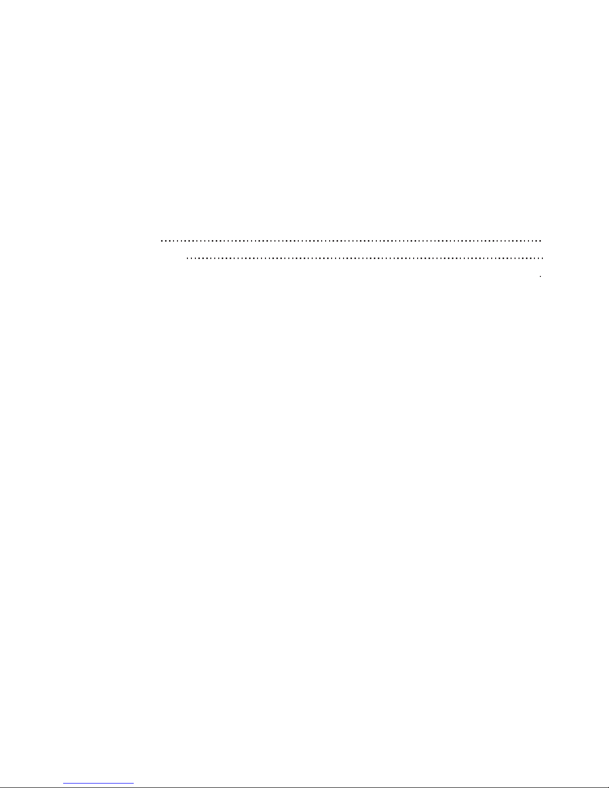
Table of contents
1. Introduction……………………………………………………………………………………………1
1.1 Important safety instructions……………………………………………………………………………1
1.2 General remarks
………………………………………………………………………………………3
1.3 Installation instructions
……………………………………………………………………………… 3
1.4 Instructions for use
…………………………………………………………………………………… 5
2. Maintenance instructions……………………………………………………………………………5
2.1 Periodic Maintenance…………………………………………………………………………………6
2.2 Troubleshooting
………………………………………………………………………………………7
3. Limited Lifetime Warranty…………………………………………………………………………10
3.1 Coverage……………………………………………………………………………………………10
3.2 Warranty Period
10
3.3 Terms and Conditions
10
3.4 Warranty service process
…………………………………………………………………………… 10
HAZARD SYMBOLS AND DEFINITIONS
DANGER
WARNING
CAUTION
Danger Sign: Indicates a hazardous situation which, if not avoided, will result in serious injury or death.
Warning Sign: Indicates a hazardous situation which, if not avoided, could result in serious injury or death.
Caution Sign: Indicates a hazardous situation which, if not avoided, could result in minor or moderate injury or
property damage.
Page 4
Page 5

1. INTRODUCTION
1.1 IMPORTANT SAFETY INSTRUCTIONS
WARNING
SAVE THESE INSTRUCTIONS
Technical data
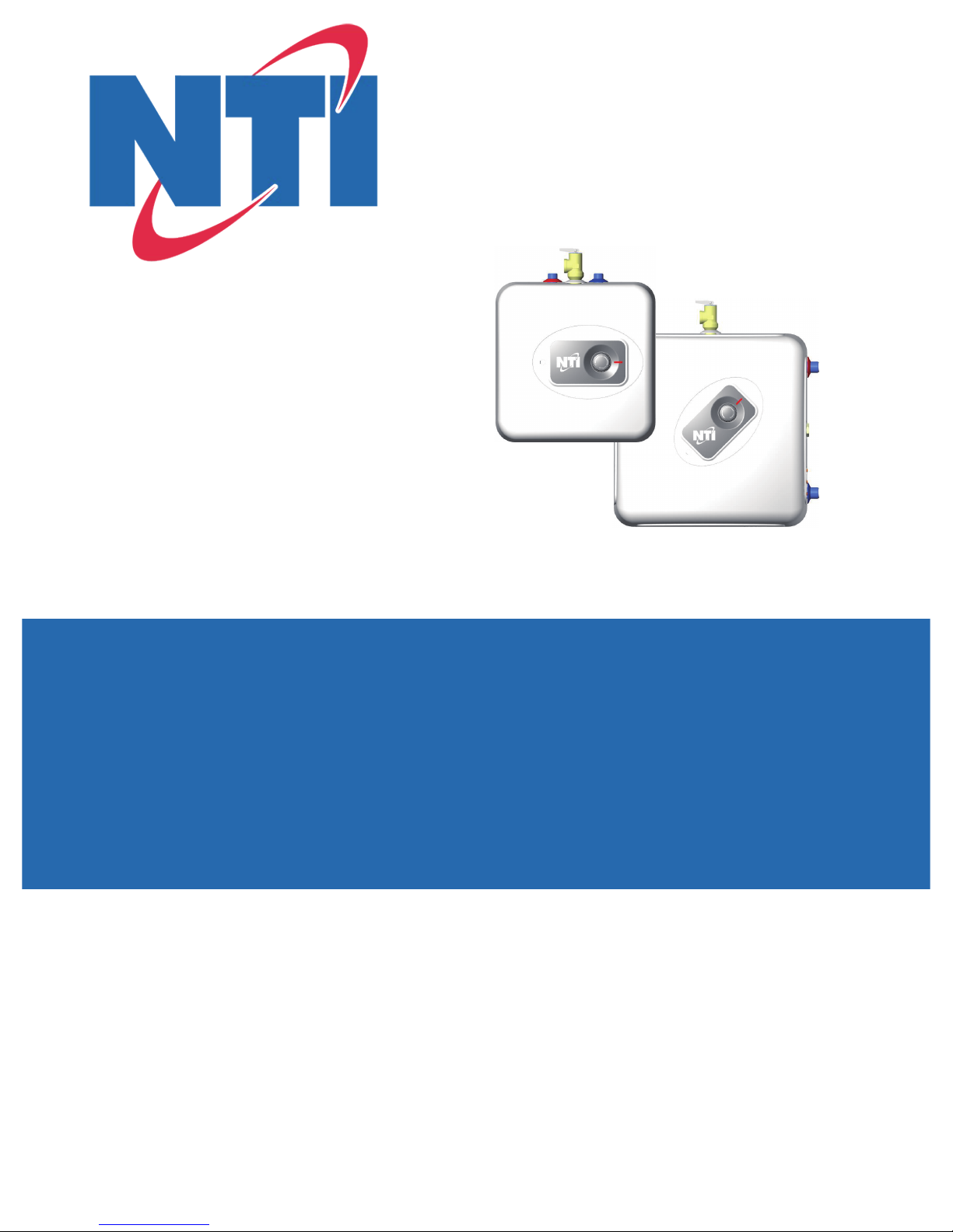
WARNING
Hot water outlet 1/2 NPT male
3/4 NPT female tapping for
relief valve
FIG. 1/1
Temperature & pressure relief valve,
3/4 NPT male
Cold water inlet 1/2 NPT male
Temperature & pressure relief
valve discharge line to drain
NTI COMPACT 2.5 - NTI COMPACT 4
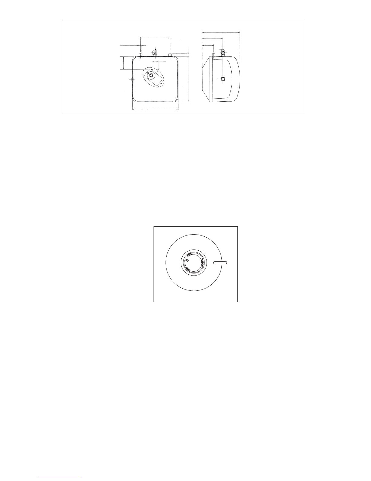
Tank capacity 2.7 gal 4.0 gal 7.0 gal *
Dimensions
13¾ ” W x 13¾ ” H x 10¾ ” D 13¾ ” W x 13¾ ” H x 13½ ”D 17⅗ ” W x 17⅗ ” H x 14½ ” D
Weight (empty) 15.5 lbs 17.3 lbs 29.5 lbs
Maximum Water pressure 150 psi 150 psi 150 psi
Recovery rate at 90°F rise 6.8 gal/h 6.8 gal/h 6.8 gal/h
Temperature range 65 – 145 °F 65 – 145 °F 65 – 145 °F
Water connections ½
” NPT ½ ” NPT ¾ ” NPT
Relief valve Installed Installed Included
Nominal Voltage (1 phase) 110/120 Vac 110/120 Vac 110/120 Vac
Nominal current 12 A 12 A 12 A
Power at 120 Vac 1,440 W 1,440 W 1,440 W
Electrical connection Plug-in Plug-in Hard wired
MODEL NTI COMPACT 2.5 NTI COMPACT 4 NTI COMPACT 6
* 5.1 gal if installed vertical
When using electrical appliances, safety precautions to reduce the risk of fire, electric shock or injury to persons should be followed,
including:
1. READ ALL INSTRUCTIONS BEFORE USING THIS WATER HEATER.
2. This water heater must be grounded. Connect only to properly grounded outlet. See “GROUNDING INSTRUCTIONS” found on
“INSTALLATION INSTRUCTIONS”.
3 .Install or locate this water heater only in accordance with the provided installation instructions.
4. Use this water heater only for its intended use as described in this manual.
5. The models NTI COMPACT 2.5 and NTI COMPACT 4 come equipped with a power cord. Do not use an extension cord. If no
outlet is available adjacent to the water heater, contact a qualified electrician to have one properly installed near the heater. The
model NTI COMPACT 6 must be hard-wired. See installation instructions.
6. As with any appliance, close supervision is necessary when used by children.
7. Do not operate this water heater if it is has a damaged cord or plug, if it is not working properly, or if it has been damaged or
dropped.
8. This water heater should be serviced only by qualified service personnel. Contact a service person for examination, repair or
adjustment.
9. Failure to inspect the anode rod at least once a year could cause the tank to fail and leak. This condition is not covered under the
manufacturer's warranty.
10.Any water heater should be installed in such a manner that if it should leak, the resulting flow of water will not cause damage to
the area in which it is installed.National Plumbing codes require a drain pan for any water heater installation. Failure to install one
is the sole responsibility of owner and/or installer. Reference UPC 2000 (Uniform Plumbing Code) Section 510 - Protection from
Damage or IPC 200 (International Plumbing Code) Section 504- Safety Devices.
The installer should review the contents of this manual with the owner upon completion of installation, and the manual should be
left with the owner and placed in a location close to the installation.
1
Page 6
Temperature & pressure
relief valve, 3/4 NPT male
3/4 NPT female tapping
for relief valve
3/4 NPT female tapping for tap
NTI COMPACT 6 (HORIZONTAL INSTALLATION)
FIG. 1/2
Temperature & pressure relief
valve discharge line to drain
Hot water outlet 3/4 NPT male
3/4 NPT male plug
Cold water inlet 3/4 NPT male
Temperature & pressure relief
valve, 3/4 NPT male
3/4 NPT female tapping for tap
3/4 NPT female tapping for
relief valve
NTI COMPACT 6 (VERTICAL INSTALLATION)
FIG. 1/3
Hot water outlet 3/4 NPT male
3/4 NPT male
Temperature & pressure relief
valve discharge line to drain
Cold water inlet
3/4 NPT male
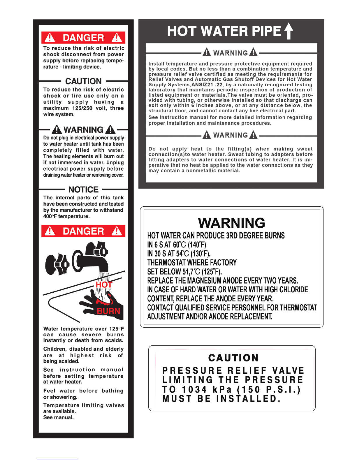
FIG. 2/1
DIMENSIONS FOR NTI COMPACT 2.5 - NTI COMPACT 4
13 3/4”
10 3/4”
13 1/2”
9”
3 1/2”
6 1/4”
3 1/2”
1”
13 3/4”
5 3/8”
3 3/4”
2 1/2”
1/2 NPT MALE
12 1/4”
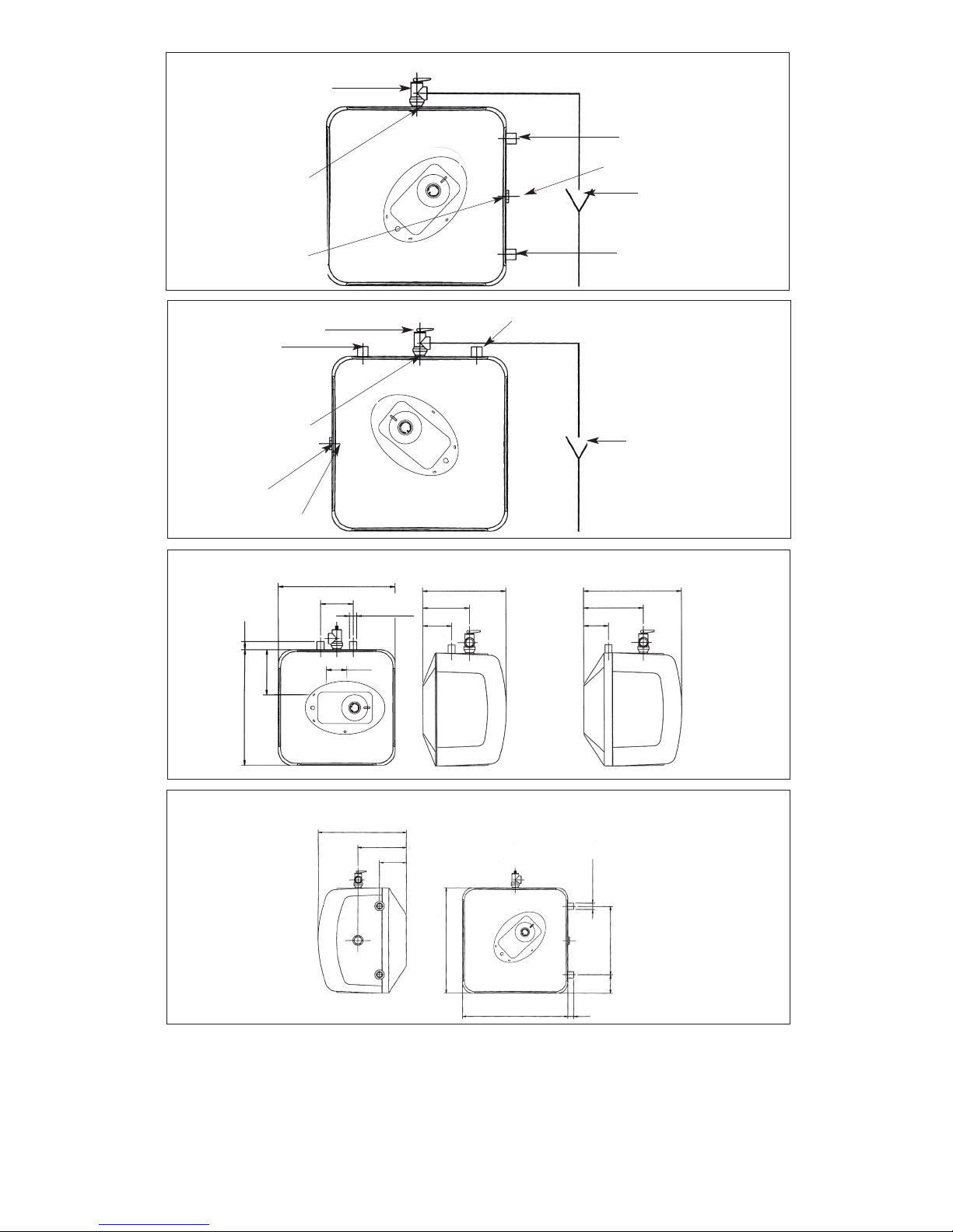
DIMENSIONS FOR NTI COMPACT6 (HORIZONTAL INSTALLATION)
FIG. 2/2
14 1/2”
8 1/2”
4 1/2”
17.6” 1”
17.6”
11.4”
3/4 NPT MALE
3”
NTI COMPACT 2.5
NTI COMPACT 4
2
Page 7
CAUTION
CAUTION
CAUTION
CAUTION
1.3 INSTALLATION INSTRUCTIONS
MODEL NTI COMPACT 2.5 - NTI COMPACT 4 - NTI COMPACT 6
The NTI COMPACT 2.5 and NTI COMPACT 4 water heaters can be installed under the sink.
Fasten the supplied mounting bracket to the wall. Use screws that are suitable for the wall material and the weight of the heater.
Hang the water heater on the bracket. Tug down wards on the heater to ensure that both “fingers” of the bracket are seated in the
mounting slots.
Wall mounting
CAUTION
CAUTION
FIG. 2/4
DIMENSIONS FOR NTI COMPACT6 (VERTICAL INSTALLATION)
FIG. 2/3
14 1/2”
8 1/2”
4 1/2”
11.4”
17.6”
17.6”
1”
3/4 NPT MALE
2 1/2”
6 1/2”
Prior to connecting the power supply, ensure tank is full of water and system is purged of air.
The manufacturer cannot be responsible for the damages caused by improper installation or by failure to follow instructions in this
manual. Comply with the installation instructions before completing electric connection.
The NTI COMPACT 2.5, NTI COMPACT 4, NTI COMPACT6 models are only approved for installations in USA.
The thermostat has been pre-set at the factory at a temperature:
- Equal or below 51.7°C (125° F) for NTI COMPACT 2.5, NTI COMPACT 4 and NTI COMPACT 6 for USA with UL certification
(See fig. 2/4).
Hydrogen gas can be produced in a hot water system served by this heater that has not been used for a long period of time (generally 2 weeks or more). Hydrogen gas is extremely flammable. To reduce the risk of injury under these conditions, it is recommen
ded that the hot water faucet be opened for several minutes at the kitchen sink before using any electrical appliance connected to
the hot water system. If hydrogen gas is present, there will probably be an unusual sound such as air escaping through the pipe as
the water begins to flow. There should be no smoking or open flame near the faucet at the time.
Any water heater should be installed in such a manner that if it should leak, the resulting flow of water will not cause damage to the
area in which it is installed. National Plumbing codes require a drain pan for any water heater installation. Failure to install one is
the sole responsibility of owner and/or installer. Reference UPC 2000 (Uniform Plumbing Code) Section 510- Protection from
Damage or IPC 2000 (International Plumbing Code) Section 504- Safety Devices.
1.2 GENERAL REMARKS
3
Page 8
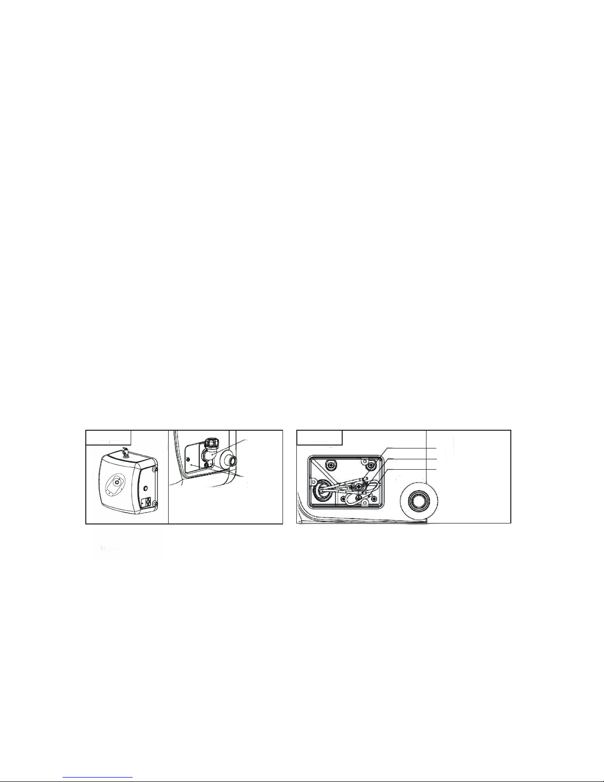
Figure BFigure A
Conduit
Junction
box
covers
White wire
Black wire
Earth connection
(Green wire)
Heater can sit on floor.
Connect the cold water inlet pipe to the inlet tapping (marked with a blue ring) and the hot water outlet pipe to the outlet tapping
(marked with a red ring).
The model NTI COMPACT 6 can be piped horizontally from the side or vertically from the top. If you wish to install the unit horizontally, with the piping connections on the right side, you will have to be certain the tap between the two water tappings is
plugged, the supplied Temperature and Pressure Relief Valve will need to be installed on top. See location of T&P relief valve in Fig.
2/2. If you wish to install the unit vertically, with the piping connections on top, you will have to be certain the tap on the side is
plugged, the supplied Temperature and Pressure Relief Valve will need to be installed on top. See location of T&P relief valve in
Fig. 2/3.
To reduce the risk of excessive pressures and temperatures in this water heater, install the supplied temperature and pressure
protective equipment required by local codes but not less than a combination temperature and pressure relief valve certified by a
nationally recognized testing laboratory that maintains periodic inspection of production of listed equipment or materials, as meeting
the requirements for Relief Valves and Automatic Gas Shut-off Devices for Hot Water Supply Systems, ANSI Z21.22. The supplied
temperature and pressure relief valve is marked with a maximum set pressure (150 psi) that does not exceed the marked
maximum working pressure of the water heater. Install the valve in the opening provided and marked for this purpose in the
water heater, and orient it or provide tubing so that any discharge from the valve will exit within 6 inches above, or at any
distance below, the structural floor,and cannot contact any live electrical part. The discharge opening must not be blocked or
reduced in size under any circumstances.
National Plumbing codes require a drain pan for any water heater installation. Failure to install one is the sole responsibility of owner
and/or installer. Reference UPC 2000 (Uniform Plumbing Code) Section 510- Protection from Damage or IPC 2000 (International
Plumbing Code) Section 504- Safety Devices.
The NTI COMPACT 6 model must be hard wired . As per the National Electric Code the NTI COMPACT 6 needs to be wired
with 12 GA. wire to a 20 amp branch circuit. Remove the junction box covers and feed wires, see Figure A and B. Insert 12 AWG
through conduit into junction box and secure with conduit strain relief (not supplied). Make appropriate wiring connections to the
water heater per the National Electric Code. The unit must be grounded with supplied grounding cable inside junction box. Secure
junction box cover once wiring connections have been made. When theNTI COMPACT 6 is not within sight of the electrical circuit
breakers, a circuit breaker lockout or additional local means of disconnection for all non grounded conductors must be provided that
is within sight of the appliance. [REF NEC 422.31]
Periodic discharge of the temperature and pressure relief valve or failure of the element gasket may be due to thermal expansion in
a closed water supply system. The water utility supply meter may contain a check valve, backflow preventer or water pressure
reducing valve which will create a closed water system. During the heating cycle of the water heater, the water expands causing
pressure inside the water heater to increase. The temperature and pressure relief valve may discharge hot water under these
conditions which results in a loss of energy and a build-up of lime on the relief valve seat.
To prevent this from happening, there are two recommendations:
1. Install a diaphragm-type expansion tank that is suitable for potable water on the cold water supply line. The expansion tank must
have a minimum capacity of 1.5 U.S. gallons for every 50 gallons of stored water.
2. Install a 125 PSI pressure relief valve in the cold water supply line. Make sure the discharge of this valve is directed to an open
drain and protected from freezing. Contact the local water supplier or plumbing inspector for information on how to control this
situation. Do not plug the temperature and pressure relief valve.
Floor Mounting
Pipe connections
CAUTION
Electrical connection
Closed system thermal expansion (for all models)
4
Page 9
DO NOT supply power to water heater until filled with water. Open supply valve for water heater to fill with water. Open hot
water tap(s) supplied by the water heater to purge air out of the system. Once air is purged, close hot water tap. Visually check
for any leaks.Supply power to the water heater by plugging in the power cord (models NTI COMPACT 2.5, NTI COMPACT 4) or
turning on the circuit breaker (model NTI COMPACT 6). If the light does not come on, turn the control knob in a clockwise
direction. The light will come on until water temperature has reached the thermostat temperature setting. The light will come back
on any time the water temperature inside the tank drops below the thermostat
setting.
The temperature of the hot water is adjusted by rotating the knob M (fig.3/1) located on the front cover. Turn the knob clockwise to
increase temperature. Turn the knob counter-clockwise to decrease temperature.
1.4 INSTRUCTIONS FOR USE
Starting and testing
Temperature Setting
2. MAINTENANCE INSTRUCTIONS
Note: Do not attempt to repair this water heater yourself. Call a service person for assistance. Always turn off the power supply to
the heater prior to servicing or draining the heater.
FIG. 3/2
G
H
E
A
Z
F
X
Y
T
FIG. 4
B
FIG. 3/1
V
C
M
W
5
Page 10
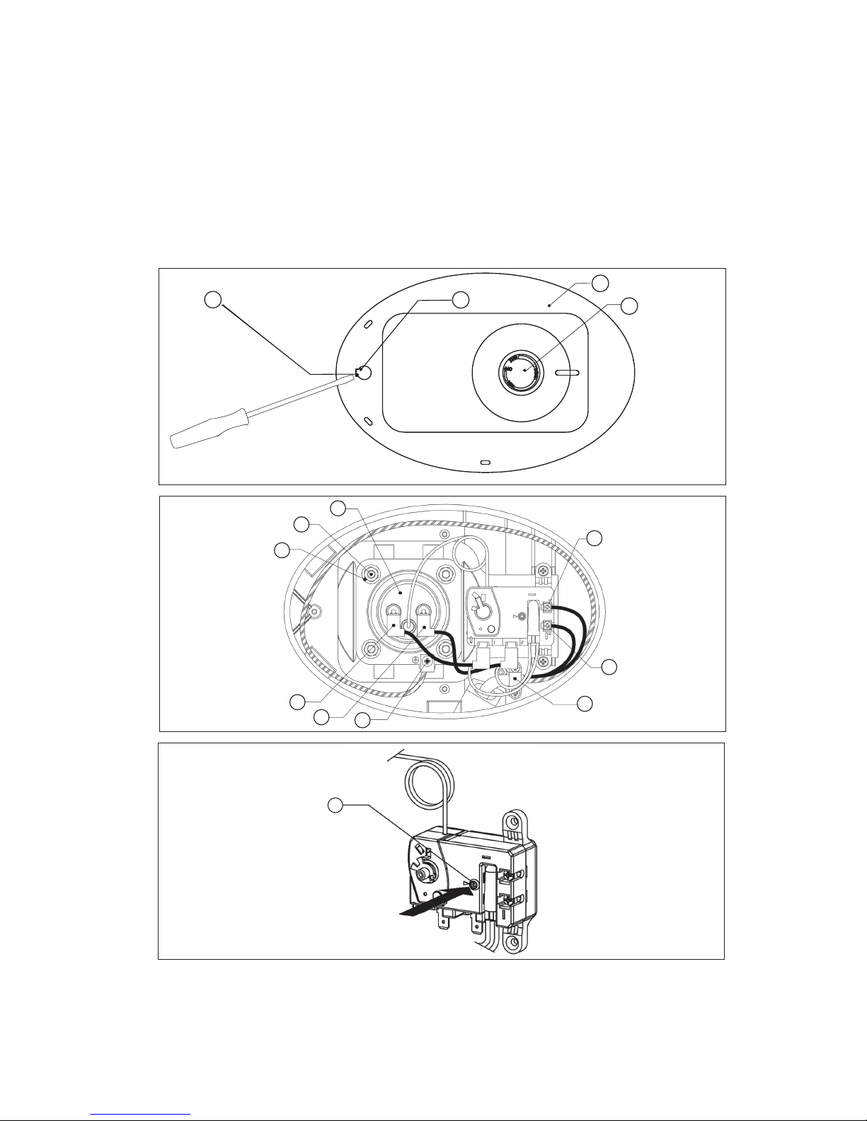
Note: For most of these operations, the water will have to be drained from the heater. For all of these operations the cord
should be disconnected and the front cover removed.
1. Pry off the round cover plate (V Fig. 3/1) from its right hand edge (W Fig. 3/1) with a small flat-head screwdriver.
2. Remove the Phillips screw revealed beneath the round cover plate.
3. The cover (C Fig. 3/1) can now be removed by pulling out its left-hand edge. When reassembling, work in the opposite
way being careful to insert the tongue of the cover into the slot.
1) If the heater has been installed with flexible hoses, shut off the power supply and turn the heater upside down over a sink to
drain the water out of it, OR
2) If the heater has been installed with rigid piping, siphon the water out through any (lower) service valve on the (inlet side). Keep a
hot water faucet open while siphoning the water out, OR
3) If the heater has been installed with flexible hoses, it can also be emptied by siphoning through the inlet side hose. Keep a hot
water faucet open while siphoning.
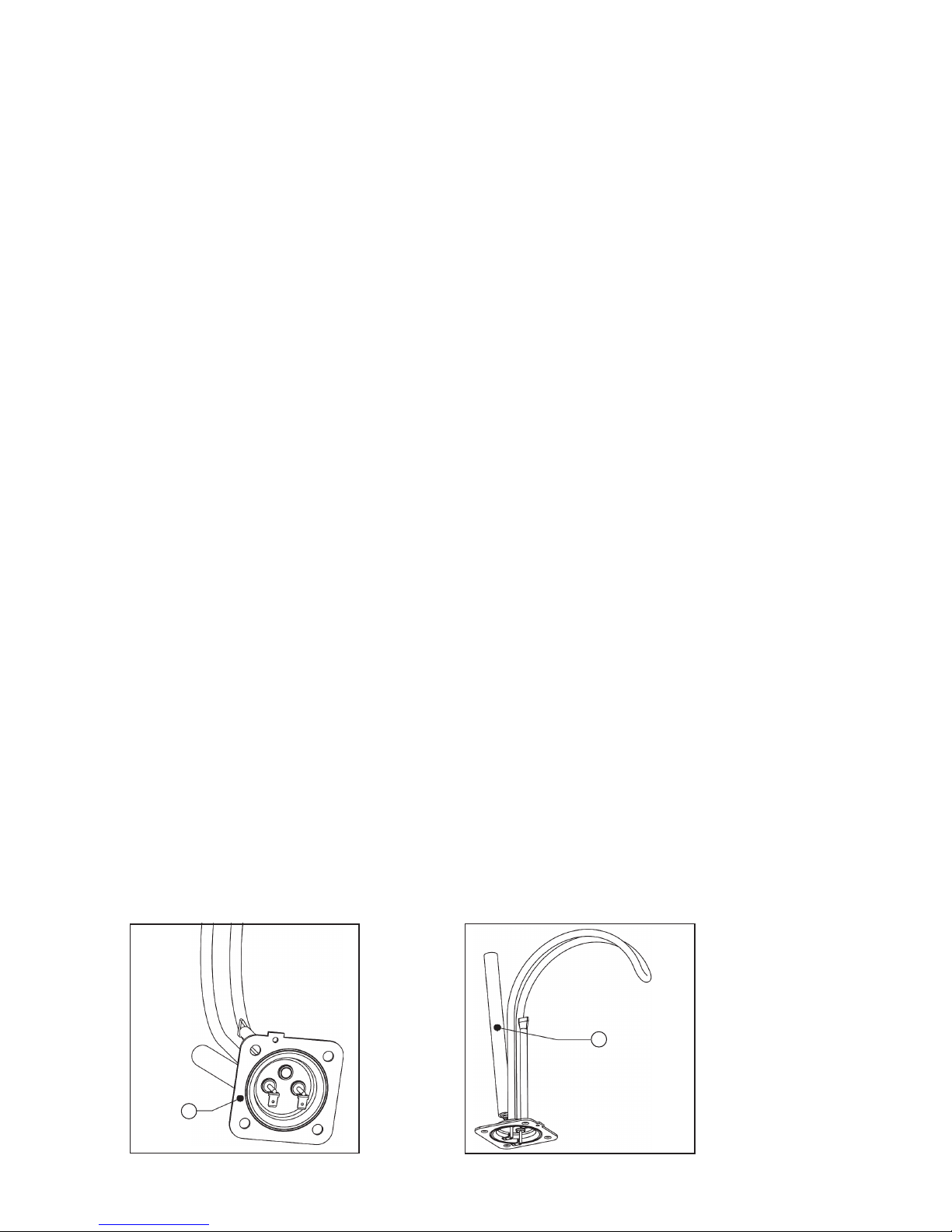
1. Turn off power supply and drain the heater (see previous section).
2. Remove the front cover plate, disconnect terminals X, Y and T (fig. 3/2).
3. Unscrew the 4 heating element retaining nuts F (fig. 3/2).
4. Remove the element. G (fig. 5/1).
The purpose of the anode rod (N Fig. 5/2) is to protect the tank against corrosion. It is critical that the anode rod be inspected
once a year to determine whether it requires replacement. To access the anode rod, the heating element must be removed (see
Section Removing the heating element). Upon inspection, the anode rod surface should appear smooth. If the rod surface appears
pitted, bumpy, rusty, or if the rod is missing completely, then it must be replaced.
For original anode rod sizes:
• NTI COMPACT 2.5, NTI COMPACT 4: length 6 _”, diameter 5/8”
• NTI COMPACT 6: length 8 _”, diameter 5/8”
Certain installations may require more frequent replacement of the anode rod:
• recirculation applications;
• poor water quality;
• galvanic/electrolytic corrosion
• High flow applications
Rusty water is usually an indication that the anode rod requires replacement. If rusty water is present, examine the anode rod
immediately and replace as needed. In the event of poor water quality, we recommend consulting a local water treatment
professional for water treatment options. Always ensure the water heater is grounded. Damage resulting from failure to replace
the anode rod is not covered under the manufacturer’s warranty. For additional questions, please call Bosch Technical Service.
To change the anode road:
1. Turn off the power supply and drain the heater (see Draining the Heater).
2. Remove heating element (see previous section).
3. Remove and replace the anode rod N Fig. 5/2.
4. Refill tank with water before restoring power.
2.1 PERIODIC MAINTENANCE
Removing the cover
Draining the Heater
Removing the heating element
Inspecting the anode rod
G
FIG. 5/1
N
FIG. 5/2
6
Page 11

Scale deposits can affect the heating capability of the element.Heavy scale can even cause the element to burn out. The element
can be descaled either chemically or manually:
A) Soak the element in white vinegar or other descaling solution. Once descaled, rinse well with fresh water, to which you should
add some baking soda, OR
B) Once the element has dried up, use a soft brush (non metallic to prevent damaging the stainless steel sheath) on element. Brush
the dried mineral off. Reinstall the element with gasket and make the wire connections.
C) Replace anode rod (N Fig. 5/2) if it is noticeably deteriorated or considerably shorter then seen in figure 5/2.
WARNING: make sure the tank has been refilled with water before restoring power.
1. Turn off power supply and drain the heater (see Draining the Heater).
2. Remove the heating element (see section on Removing the Heating Element).
3. Install new element with gasket, making sure the gasket and element are positioned correctly. Tighten the retaining nuts and
make the wire connections. Ensure that the thermostat temperature sensor is inserted into the well located on the element
assembly and secured with black rubber grommet.
4. Refill tank with water before restoring power.
1. Turn off power supply.
2. Disconnect the 2 wire connectors on thermostat.
3. Loosen the two brass screws at right side of thermostat and pull wires out.
4. Unscrew and remove the two phillips screws holding the thermostat onto the tank.
5. Install new thermostat and re-attach wiring and screws. Ensure that the thermostat temperature sensor is inserted into the well
located on the element assembly and secured with black rubber grommet.
Occasionally, the high temperature limit shut off device may trip the reset. This occurs when water temperature exceeds
190° F. The shut off device may also trigger from a power outage or electrical storm.
To reach the thermostat:
1. Disconnect power cord and remove the front cover. Firmly press reset button (B Fig. 4) with the tip of a ball point pen or similar
object. A click indicates the reset was tripped. Reconnect power
2. IMPORTANT: Check the operation of the thermostat, turn temperature dial from high to low, if the red light does not go off on low
setting, turn off power supply and call a service person to replace the thermostat
3. If the system works, place dial setting to desired setting. Note: a lower setting is more economical and reduces the risk of scalding.
Replace cover plate.
CAUTION : Call a technician if the high limit need to be reset frequently.
1. Make sure the power supply is on and working.
2. If light does not come on, check that the high limit reset button is pushed in; follow steps above.
3. If the indicator light works properly but temperature does not get hot at the tap, test for a plumbing crossover; shut off cold supply to heater
and open hot water tap. There should be no water flowing. Any continued flow indicates a crossover which will effect the temperature
and will need to be corrected.
4. Call a qualified service technician to test the resistance of the heating element (8-10 ohms). Heating element should be replaced
if readings are outside these values.
1. If the light does not come on, but water gets hot, check for faulty bulb.
2. Check that the high limit reset button is pushed in; follow steps above.
1. Brown or rusty water indicates a “spent” anode rod and possible deterioration of the tank body. Inspect the tank for leaks.
1. Smelly water could be due to an unusual reaction between local water and the heater’s anode rod. Check anode rod (see section on
Inspecting the anode rod). Failure to do so may result in damage to the tank and leaks.
Descaling the heating element
REPLACEMENT OF PARTS
Changing the heating element
Changing the thermostat
2.2 TROUBLESHOOTING
Reset ting High Limit Switch
Water does not get hot
Light not on
Brown water
Odor in water
7
Page 12

Leaking
1. Check water fitting and T&P fitting on top of tank
2. Remove front cover and inspect heating gasket
3. If tank is leaking call NY Thermal Inc. TI for warranty claim if still within warranty period.
8
Page 13

FIG. 6 INTERIOR COMPONENTS DIAGRAM
PARTS LIST
Parts are available at any stocking
wholesaler. Installers needing
technical assistance can contact
NTI directly at 1-800-688-2575.
DESCRIPTION REF.
NTI COMPACT 2.5
NTI COMPACT 4
NTI COMPACT 6
A
B
C
.FERNOITPIRCSEDEDOCTRAP
1 86059 HEATING ELEMENT 1440W 220V A; B
1 86060 HEATING ELEMENT 1440W 220V C
3 86061 WIRED THERMOSTAT A; B
3 86062 THERMOSTAT C
7 86063 HEATER WALL HANGING BRACKET A; B; C
141486064
86065
PLASTIC COVER + SIGNAL LAMP CAP
PLASTIC COVER + SIGNAL LAMP CAP
A; B
C
C;B;ABONK8606681
C;B;A4”/3P&TEVLAV8606722
23 86068 MAGNESIUM ANODE D:14 L:155 M4 A; B
232786069
86078MBRASS PLUG 3/4”
AGNESIUM ANODE D:16 L:195 C
C
C;B;A6MTUNKCOL8607013
33 86071 GASKET WITH 4 BOLTS A; B; C
C;B;APMALCELBAC8607344
B;AELBACREWOP8607405
70 86076 LEVER THERMOSTAT A; B; C
A; B; C
9
50 86075 POWER CABLE
C
WIRED
38
86072
SCREW COVER
7
1
38
33
14
38
50
23
50
18 14
70
22
3
31
44
18
1
NTI COMPACT 6
27
Page 14

3 LIMITED LIFETIME WARRANTY
3.1 COVERAGE
NY Thermal Inc. (hereinafter NTI) guarantees this water
heater to the owner of the water heater (hereinafter “Owner”)
at the original installation locationagainst defects in material
and workmanship for the periods and the terms and
conditions specified below.This warranty is provided as long
as the Water Heater remains in the possession of the original
purchaser and installed at its original place of installation.
3.2 WARRANTY PERIOD
1. The inner Tank - If the inner tank leaks within six (6) years from
the date of original installation of the water heater, because of
a defect in material or workmanship,NTI will furnish to such
Owner a new heater of the then prevailing comparable model.
2. Any Component Part Other than The Original Inner Tank - If
any component part (other than the inner tank) proven to be
defective in material or workmanship within one (1) year from the
date of original installation of the water heater, NTI will furnish
the Owner with a replacement of the defective part(s).
3. Verification of Date of Original Installation – When owner
cannot verify or document the original date of installation,
the warranty period begins on the date of manufacture marked
on the tag affixed to the water heater.Please register your product
online (www.ntiboilers.com) to allow NTI to provide a better services.
3.3 TERMS AND CONDITIONS
1. THIS LIMITED WARRANTY SHALL BE THE EXCLUSIVE
WARRANTY MADE BY THE MANUFACTURER AND IS MADE IN
LIEU OF ALL OTHER WARRANTIES, EXPRESSED OR IMPLIED
(WHETHER WRITTEN OR ORAL), INCLUDING,BUT NOT
LIMITED TO, WARRANTIES OF MERCHANTABILITY AND
FITNESS FOR A PARTICULAR PURPOSE.
2. The Manufacturer shall not be liable for any incidental,
consequential, special or contingent damages or expenses arising,
directly or indirectly, from any defect in the water heater or the
use of the water heater.
3. The Manufacturer shall not be liable for any water damage arising,
directly or indirectly, from any defect in the water heater component
part(s) or from its use.
4. Manufacturer shall not be liable under this warranty if:
a) The water heater or any of its component parts has been
subject to misuse, alteration, neglect or accident, or
b) The water heater has not been installed in accordance with the
applicable local plumbing and/or building code(s) and/or
regulation(s), or
c) The water heater has not been installed in accordance with the
printed manufacturer’s instructions, or
d) The water heater is not continuously supplied with potable
water.
5.The OWNER and not the Manufacturer or his representative shall be
liable for and shall pay for all field charges for labor or other expenses
incurred in the removal and/or repair of the product or any expense
incurred by the owner in order to repair the product.
SOME STATES DO NOT ALLOW THE EXCLUSION OR
LIMITATION OF INCIDENTAL OR CONSEQUENTIAL DAMAGES,
SO THE ABOVE LIMITATION OR EXCLUSION MAY NOT APPLY
TO YOU. THIS WARRANTY GIVES YOU SPECIFIC LEGAL
RIGHTS AND YOU MAY ALSO HAVE OTHER RIGHTS WHICH
MAY VARY FROM STATE TO STATE.
NOTE: A water heater should be installed in such a manner that if it
should leak, the resulting flow of water will not cause damage to the
area in which it is installed.
3.4 WARRANTY SERVICE PROCESS
1. Owner should contact the installer or dealer who sold the water
heater covered by this warranty. Do not call NTI. If the contractor or
dealer requires further help,they will call NTI.
2. If Owner cannot contact the contractor or dealer,Owner may
contact NTI at 1-506-657-6000 to the attention of the Service
Department.
NOTE: NTI cannot provide technical assistance tohomeowners unless they are licensed and trained Plumbing and
Electric Contractor
3. NTI will replace or credit the parts under warranty. Credits are
issued to the authorized wholesaler at their cost. No credit or
reimburement will be issued by NTI directly to the Owner.
10
Page 15

1. Introduction 13
1.1 Importantes consignes de sécurité 13
1.2 Remarques générales
15
1.3 Consignes d’installation
15
1.4 Consignes d’utilisation
17
2. Recommandations d’entretien 17
2. 1 Entretien périodique 18
2. 2 Résolution de problèmes
19
3. Garantie limitée à vie 22
3.1 Couverture 22
3.2 Période de Garantie
22
3.3 Termes et Conditions
22
3.4 Démarches pour l’activation de la garantie
22
DANGER
MISE EN GARDE
ATTENTION
Signe de DANGER: Indique une situation dangereuse qui, si elle n'est pas évitée, entraînera des blessures
graves ou la mort.
Signe de mise en garde: Indique une situation dangereuse qui, si elle n'est pas évitée, pourrait entraîner des
blessures graves ou la mort.
Signe attention: Indique une situation dangereuse qui, si elle n'est pas évitée, pourrait entraîner des blessures
mineures ou modérées ou des dommages matériels
Table des matières
SYMBOLES DE DANGER ET DÉFINITIONS
11
Page 16

12
Page 17

Lorsque vous utilisez des électroménagers, il y a des consignes de sécurité visant à réduire les risques d’incendie, de choc
électrique ou de blessures corporelles, dont celles qui suivent :
1. LISEZ ATTENTIVEMENT TOUTES LES DIRECTIVES AVANT D’UTILISER CE CHAUFFE-EAU.
2. Ce chauffe-eau doit être mis à la terre. Branchez-le uniquement dans une prise mise à la terre correctement. Voir les " Directives
de mise à la terre " se trouvant à la section intitulée " DIRECTIVES D’INSTALLATION ".
3. N’installez ce chauffe-eau ou ne choisissez son emplacement que conformément aux directives d’installation fournies.
4. N’utilisez ce chauffe-eau que pour l’usage auquel il est destiné, tel que décrit dans le présent manuel.
5. Les modèles NTI COMPACT 2.5 and NTI COMPACT 4 sont équipés d'un câble d'alimentation. Ne pas utiliser une rallonge.
Si aucune prise n'est disponible à proximité du chauffe-eau, veuillez contacter un électricien qualifié pour son installation
à proximité de l'appareil. Le modèle ES8 doit être câblé. Voir les instructions d'installation.
6. Comme c’est le cas avec tout électroménager, il faut surveiller étroitement les enfants lorsqu’ils utilisent ce chauffe-eau.
7. Ne mettez pas le chauffe-eau en marche s’il ne fonctionne pas bien, s’il est endommagé ou s’il a été échappé par terre.
8. Ce chauffe-eau ne devrait être réparé ou entretenu que par un réparateur accrédité. Adressez-vous à un réparateur si le
chauffe-eau doit être examiné, réparé ou réglé.
9. Le défaut d'inspection de la tige d'anode, au moins une fois par an, peut nuire au fonctionnement du réservoir et provoquer des
fuites. Cette condition n'est pas couverte par la garantie du fabricant.
10. Tout chauffe-eau devrait être installé de telle façon qu’en cas de fuite, l’écoulement d’eau en résultant n’endommagera pas
l’endroit où il se trouve. Les codes de plomberie exigent l’ajout d’un bac de récupération lors de l’installation d’un
chauffe-eau. Le défaut d’installer un tel bac sera imputé au propriétaire et(ou) à l’installateur. Références : UPC 2000 (Code
de plomberie normalisé), article 510 – Protection contre les dommages ou IPC 200 (Code de plomberie international), article
504 – Dispositifs de sécurité.
1.1 IMPORTANTES CONSIGNES DE SÉCURITÉ
MISE EN GARDE
IL FAUT CONSERVER CES DIRECTIVES.
Données techniques
MISE EN GARDE
L’installateur devrait passer en revue le contenu de ce manuel avec le propriétaire une fois l’installation terminée et lui laisser le
manuel, qui devrait être placé à proximité du lieu de l’installation.
”
”
”
”
”
”
”
”
”
”
”
”
MODÈLE NTI COMPACT 2.5 NTI COMPACT 4 NTI COMPACT 6
* 5.1 gal si installation vertical
Capacité
Dimensions
Poids (vide)
Pression maximale de l’eau
Taux de rétablissement à 90°F hausse
Gamme de température
Connexions d'eau
soupape de sûreté
Tension (1 phase)
Intensité du courant
Puissance à 120 V c.a.
connexion électrique
câblé
Installé Installé compris
1. INTRODUCTION
Raccord de sortie d’eau
chaude mâle NPT de 13 mm (1/2 po)
Prise femelle NPT de 19
mm (3/4 de po) pour la
soupape de décharge
FIG. 1/1
Raccord mâle NPT de 19 mm (3/4 de po)
de la soupape de décharge et de sécurité
thermique
Raccord d’admission d’eau froide mâle
NPT de 13 mm (1/2 po)
Conduite de la soupape de décharge
et de sécurité thermique vers le drain
NTI COMPACT 2.5 - NTI COMPACT 4
13
Page 18

Raccord mâle NPT de 19
mm (3/4 de po) de la soupape
de décharge et de sécurité thermique
Prise femelle NPT de 19
mm (3/4 de po) pour la
soupape de décharge
Prise femelle NPT de 19 mm
(3/4 de po)
NTI COMPACT 6 installation horizontale
FIG. 1/2
Conduite de la soupape de
décharge et de sécurité
thermique vers le drain
Raccord de sortie d’eau chaude
mâle NPT de 19 mm (3/4 po)
Bouchon mâle NPT de 19 mm
(3/4 de po)
Raccord d’admission d’eau
froide mâle NPT de 19 mm
(3/4 po)
Raccord mâle NPT de 19 mm (3/4 de po) de la
soupape de décharge et de sécurité thermique
Prise femelle NPT de 19 mm
(3/4 de po)
Prise femelle NPT de 19 mm
(3/4 de po) pour la soupape
de décharge
NTI COMPACT 6 installation verticale
FIG. 1/3
Raccord de sortie d’eau chaude
mâle NPT de 19 mm (3/4 po)
Bouchon mâle NPT
de 19 mm (3/4 de po)
Conduite de la soupape de
décharge et de sécurité
thermique vers le drain
Raccord d’admission d’eau froide mâle NPT
de 19 mm (3/4 po)
FIG. 2/1
DIMENSIONS DES MODÈLES NTI COMPACT 2.5 - NTI COMPACT 4
13 3/4”
10 3/4”
13 1/2”
9”
3 1/2”
6 1/4”
3 1/2”
1”
13 3/4”
5 3/8”
3 3/4”
2 1/2”
1/2 NPT MÂLE
12 1/4”
DIMENSIONS DU MODÈLE NTI COMPACT6 (INSTALLATION HORIZONTALE)
FIG. 2/2
14 1/2”
8 1/2”
4 1/2”
17.6” 1”
17.6”
11.4”
MÂLE NPT de 19 mm
3”
NTI COMPACT 2.5
NTI COMPACT 4
14
Page 19

DIMENSIONS DU MODÈLE NTI COMPACT6 (INSTALLATION VERTICALE)
FIG. 2/3
14 1/2”
8 1/2”
4 1/2”
11.4”
17.6”
17.6”
1”
MÂLE NPT de 19 mm
2 1/2”
6 1/2”
1.2 REMARQUES GÉNÉRALES
Avant le raccordement de l'alimentation électrique, s'assurer que le réservoir est plein d'eau et le système est purgé d'air.
Le fabricant décline toute responsabilité à l’égard des dommages causés par une installation inadéquate ou par le défaut de
respecter les directives contenues dans le présent manuel. Il importe de respecter les directives d’installation avant de procéder
à la connexion électrique.
Les modèles de NTI COMPACT 2.5, NTI COMPACT 4, NTI COMPACT 6 sont seulement approuvés pour des installations au USA
Le thermostat a été pré-réglé en usine à une température:
- Egale ou inférieure à 51,7°C (125°F) pour les modèlesNTI COMPACT 2.5, NTI COMPACT 4, NTI COMPACT6 pour USA avec
certification UL (Voir fig. 2/4).
De l’hydrogène peut être produit dans un système d’eau chaude desservi par ce chauffe-eau s’il n’a pas été utilisé pendant une
période prolongée (habituellement deux semaines ou plus). L’hydrogène est un gaz très inflammable. Pour réduire les risques de
blessures dans de telles circonstances, on recommande d’ouvrir le robinet d’eau chaude pendant plusieurs minutes avant d’utiliser
quelque électroménager que ce soit, qui est relié au système d’eau chaude. S’il y a présence d’hydrogène, il y aura probablement
un bruit inusité comme un bruit d’air s’échappant par le tuyau lorsque l’eau commencera à couler. Il ne faut pas
fumer près du robinet à ce moment, ni approcher une flamme nue.
Tout chauffe-eau devrait être installé de telle façon qu’en cas de fuite, l’écoulement d’eau en résultant n’endommagera pas
l’endroit où il se trouve. Les codes de plomberie exigent l’ajout d’un bac de récupération lors de l’installation d’un chauffe-eau. Le défaut
d’installer un tel bac sera imputé au propriétaire et(ou) à l’installateur. Références : UPC 2000 (Code de plomberie normalisé),
article 510 – Protection contre les dommages ou IPC 200 (Code de plomberie international), article 504 – Dispositifs de sécurité.
ATTENTION
ATTENTION
ATTENTION
ATTENTION
ATTENTION
ATTENTION
Installation murale
FIG. 2/4
1.3 CONSIGNES D'INSTALLATION
Les chauffe-eau NTI COMPACT 2.5 et NTI COMPACT 4 peuvent être installés sous l’évier.
MODÈLES NTI COMPACT 2.5 - NTI COMPACT 4 - NTI COMPACT 6
Fixez le support de montage fourni au mur. Utilisez des vis convenant au matériau du mur et au poids du chauffe-eau. Suspendez le
chauffe-eau au support. Tirez le chauffe-eau vers le bas pour vous assurer que les deux " langues " du support sont bien insérées
dans les fentes de fixation.
15
Page 20

Le chauffe-eau peut reposer sur le plancher.
Raccordez la conduite d’alimentation d’eau froide au mamelon d’admission (indiqué par un anneau bleu), et la conduite de sortie
d’eau chaude au mamelon de sortie (indiqué par un anneau rouge).
Les conduites du modèle NTI COMPACT 6 peuvent être raccordées horizontalement à partir du côté ou verticalement à partir du dessus. Si vous désirez installer l’appareil à l’horizontale, avec les raccordements de tuyauterie du côté droit, vous devrez vous assurer
que le robinet se trouvant entre les deux conduites d’eau est couché, et il faudra installer la soupape de décharge et de sécurité
thermique fournie sur le dessus. Voir son emplacement à la fig. 2/2.
Si vous désirez installer l’appareil à la verticale, avec les raccordements de tuyauterie sur le dessus, vous devrez vous assurer que
le robinet se trouvant sur le côté est bouché, et il faudra installer la soupape de décharge et de sécurité thermique fournie sur le
dessus. Voir son emplacement à la fig. 2/3.
Pour réduire les risques de pressions et de températures excessives dans ce chauffe-eau, installez le dispositif de protection
contre les températures et les pressions excessives qui est fourni, tel qu’exigé par les codes locaux. Ce dispositif doit être, à tout le
moins, une combinaison de soupape de décharge et de sécurité thermique certifiée par un laboratoire d’essais reconnu à l’échelle nationale, qui inspecte périodiquement la production d’équipement et de dispositifs homologués pour s’assurer qu’ils respectent les exigences de la norme ANSI Z21.22 visant les soupapes de sécurité et les dispositifs d’arrêt automatique du gaz pour les
systèmes d’alimentation en eau chaude. La soupape de décharge et de sécurité thermique fournie indique une pression maximale
préréglée (1 035 KPa ou 150 lb/po2) qui ne dépasse pas la pression de fonctionnement maximale indiquée du chauffe-eau. Installez
la soupape dans l’ouverture prévue et indiquée à cette fin dans le chauffe-eau et orientez-la ou branchez-y une tubulure de façon
à ce que toute décharge sortant de la soupape soit évacuée à au plus 15 cm (6 po) au-dessus ou à toute distance en dessous du
plancher porteur et ne puisse pas entrer en contact avec un appareil électrique sous tension. L’ouverture de décharge doit être
bloquée, ou sa taille doit être réduite dans tous les cas.
Les codes de plomberie exigent l’ajout d’un bac de récupération lors de l’installation d’un chauffe-eau. Le défaut d’installer un tel bac
sera imputé au propriétaire et(ou) à l’installateur. Références : UPC 2000 (Code de plomberie normalisé), article 510 –
Protection contre les dommages ou IPC 200 (Code de plomberie international), article 504 – Dispositifs de sécurité.
Le modèle NTI COMPACT 6 doit être câblé. Selon le Code national de l'électricité, les NTI COMPACT 6 doivent être câblés,
avec un câble 12 GA, à un circuit de dérivation de 20 ampères. Dévisser le couvercle de la boite électrique, et l’enlever, comme illustré
figures A et B. Insérer 12 AWG à travers le conduit dans la boîte de jonction et le fixer avec le dispositif anti-traction (non fourni).
Reliez les fils et revisser la couvercle de la boite électrique. Effectuer les raccordements nécessaires pour le chauffe-eau selon
le Code national de l'électricité. L'unité doit être mise à la terre avec le câble de terre fourni à l'intérieur de la boîte de jonction. Fixer
le couvercle de sécurité de la boîte de jonction après avoir réalisé les raccordements. Lorsque le NTI COMPACT 6 n'est pas à
portée de vue des disjoncteurs électriques, un dispositif de verrouillage pour disjoncteur ou d'autres moyens locaux de déconnexion
pour tous les conducteurs non mis à la terre doit être placé à portée de vue de l'appareil. [REF NEC 422,31].
Installation au sol
Raccordement des conduites
ATTENTION
Raccordements électriques
Figure B
Conduit
câble blanc
câble noir
câble de terre
(câble vert)
Figure A
Dilatation thermique dans un système fermé (pour tous les modèles)
Il se peut qu’un écoulement de la soupape de décharge et de sécurité thermique ou une défaillance du joint d’étanchéité de
l’élément se produise périodiquement en raison de la dilatation thermique dans un système fermé d’alimentation en eau. Le compteur d’eau du service public d’alimentation peut contenir un clapet antiretour, un dispositif antirefoulement ou un robinet réducteur
de pression d’eau, qui créera un circuit fermé de circulation d’eau. Durant le cycle de chauffage de l’eau, l’eau se dilate, ce
qui entraîne une hausse de la pression à l’intérieur du chauffe-eau. La soupape de décharge et de sécurité thermique peut alors
décharger de l’eau chaude, ce qui entraîne une perte d’énergie et une accumulation de calcaire sur le siège de la soupape. Pour
éviter que cela se produise, il y a deux recommandations:
1. Installez un vase d’expansion de type diaphragme, qui convient à l’eau potable, sur la conduite d’alimentation en eau froide.
Le vase d’expansion doit avoir une capacité minimale de 5,25 litres (1,5 gallon) pour chaque tranche de 175 litres (50 gallons)
d’eau emmagasinée.
2. Installez une soupape de décharge de 862,5 kPa (125 po/lb2) sur la conduite d’alimentation en eau froide. Assurez-vous que la
décharge de cette soupape est dirigée vers un drain ouvert et qu’elle est protégée contre le gel. Adressez-vous au fournisseur
d’eau local ou à un inspecteur de plomberie pour obtenir de l’information sur la façon de contrôler cette situation. Ne bouchez
pas la soupape de décharge et de sécurité thermique.
16
Couvercle
de la boîte
de jonction
Page 21

FIG. 3/2
G
H
E
A
Z
F
X
Y
T
FIG. 4
B
2. RECOMMANDATIONS D'ENTRETIEN
Remarque: N’essayez pas de réparer ce chauffe-eau vous-même. Faites appel à un réparateur pour obtenir de l’aide.
Débranchez toujours l’alimentation électrique du chauffe-eau avant de procéder à l’entretien ou à la purge du
chauffe-eau.
1.4 CONSIGNES D'UTILISATION
Mise en marche et essai
Réglage de la temperature
NE PAS brancher le chauffe-eau à l'électricité avant qu'il ne soit rempli d'eau.Ouvrir la soupape d'alimentation pour remplir
d'eau le chauffe-eau. Ouvrir le(s) robinet(s) d'eau chaude du chauffe-eau pour évacuer l'air du système. Une fois que l'air est
purgé, fermer le robinet d'eau chaude. Contrôle visuel pour déceler toute fuite. Alimenter le chauffe-eau en branchant le
cordon d'alimentation (modèles NTI COMPACT 2.5, NTI COMPACT 4) ou en mettant en marche le disjoncteur (modèle NTI
COMPACT 6). Si la lumière ne s'allume pas, tournez le bouton de commande dans le sens des aiguilles d'une montre. La lumière
s'allumera jusqu'à ce que soit atteinte la température de l'eau réglée sur le thermostat. La lumière se rallume si la température
de l'eau dans le réservoir descend en dessous du réglage du thermostat.
La température de l'eau chaude est réglée en tournant le bouton M (Fig. 3/1) situé sur le capot avant. Tourner le bouton dans le
sens des aiguilles d'une montre pour augmenter la température. Tourner le bouton dans le sens contraire des aiguilles d'une
montre pour diminuer la température.
FIG. 3/1
V
C
M
W
17
Page 22

G
FIG. 5/1
N
FIG. 5/2
2.1 ENTRETIEN PÉRIODIQUE
Enlever la couverture
Purge du chauffe-eau
Enlèvement de l’élément chauffant
Remarque: Pour effectuer la plupart de ces opérations, il faut purger l’eau du chauffe-eau. Il faut couper l’électricité et
enlever le couvercle avant.
1. Dégagez la plaque d’identification ronde (" V " à la fig. 3/1) en soulevant son rebord droit (" W " à la fig. 3/1)
à l’aide d’un petit tournevis à lame plate.
2. Enlevez la vis à tête Phillips qui apparaît sous la plaque d’identification ronde.
3. Le couvercle (" C " à la fig. 3/1) peut maintenant être enlevé en soulevant son rebord gauche. Lors
du réassemblage, procédez de façon inverse en faisant attention de bien insérer la langue du couvercle
dans la fente.
1) Si le chauffe-eau est muni d’une tuyauterie souple, coupez l’alimentation électrique et tournez le chauffe-eau à l’envers
au-dessus d’un évier pour le vider de son eau OU
2) Si le chauffe-eau est muni d’une tuyauterie rigide, siphonnez l’eau par n’importe quel robinet de service (inférieur) du côté de
la conduite d’admission. Gardez un robinet d’eau chaude ouvert pendant que vous siphonnez l’eau OU
3) Si le chauffe-eau est muni d’une tuyauterie souple, vous pouvez le vider en siphonnant l’eau par le tuyau se trouvant du côté
de l’admission d’eau. Gardez un robinet d’eau chaude ouvert pendant que vous siphonnez l’eau.
1. Coupez l’alimentation électrique et purgez le chauffe-eau (voir la section précédente).
2. Enlevez le couvercle avant et débranchez les bornes X, Y et T (fig. 3/2).
3. Dévissez les quatre écrous de fixation de l’élément chauffant (" F " à la fig. 3/2).
4. Enlevez l’élément (" G " à la fig. 5/1).
Le but de la tige d'anode (N Fig. 5/2) est celui de protéger le réservoir contre la corrosion. Il est essentiel que la tige d'anode soit
inspectée une fois par an afin de déterminer si elle doit être remplacée. Pour avoir accès à la tige d'anode, l'élément chauffant
doit être retiré ( voir le point Enlèvement de l’élément chauffant). Lors de l'inspection, la surface de la tige d'anode doit apparaître
lisse. Si la surface de la tige apparaît piquée, bosselée, rouillée ou si la tige est absente, alors elle devra être remplacée.
Tailles des tiges d'anodes originales
• NTI COMPACT 2.5, NTI COMPACT 4:: longueur 6_", diamètre 5/8"
• NTI COMPACT 6: longueur 8_", diamètre 5/8"
Certaines installations peuvent nécessiter d'un remplacement plus fréquent de la tige d'anode:
• applications de recirculation;
• mauvaise qualité de l'eau;
• corrosion galvanique/électrolytique
• applications à haut débit
Une eau rouillée est habituellement une indication que la tige d’anode est "usée". Si l’eau est rouillée, examinez la tige d’anode
immédiatement. En cas de mauvaise qualité de l'eau, nous raccomandons de consulter un professionnel local de traitement d'eau
pour des options de traitement des eaux. Toujours s'assurer que le chauffe-eau est mis à la terre. Les dommages résultant d'un
défaut de remplacement de l'anode ne sont pas couverts par la garantie du fabricant. Pour toutes questions supplémentaires,
veuillez appeler le service technique Bosch.
Changement de la tige d’anode:
1. Coupez l’alimentation électrique et purgez le chauffe-eau (voir la section intitulée "Purge du chauffe-eau").
2. Enlevez l’élément chauffant (voir la section précédente).
3. Enlevez et remplacez la tige d’anode ("N" à la fig. 5/2).
4. Remplissez le réservoir d’eau avant de rétablir le courant.
Inspection de la tige d'anode
18
Page 23

REMPLACEMENT DE PIÈCES
Détartrage de l’élément chauffant
Des dépôts de tartre peuvent affecter la capacité chauffante de l’élément.
Une grande quantité de tartre peut même faire sauter l’élément. L’élément peut être détartré chimique-ment ou manuellement:
A) Faites tremper l’élément dans du vinaigre blanc ou une autre solution de détartrage. Une fois détartré, rincez-le bien avec
de l’eau douce à laquelle vous aurez ajouté un peu de bicarbonate de soude, OU
B) Quand l’élément sera sec, utilisez une brosse douce (non métallique pour éviter d’endommager la gaine d’acier inoxydable) sur
l’élément. Enlevez le tartre desséché avec la brosse. Réinstallez l’élément et son joint d’étanchéité, puis rebranchez les fils.
C) Remplacez la tige d’anode (" N " à la fig. 5/2) si elle est manifestement détériorée ou considérablement plus courte que celle
illustrée à la figure 5/2.
MISE EN GARDE: Assurez-vous que le réservoir a été rempli avant de rétablir le courant.
Remplacement de l’élément chauffant
1. Coupez l’alimentation électrique et purgez le chauffe-eau (voir la section intitulée " Purge du chauffe-eau ").
2. Enlevez l’élément chauffant (voir la section intitulée "Enlèvement de l’élément chauffant").
3. Installez le nouvel élément et son joint d’étanchéité, en veillant à ce qu’ils soient bien placés. Serrez les écrous de fixation et
branchez les fils. S'assurer que le capteur de température du thermostat est inséré dans le puits situé sur l'élément d'assemblage
et qu'il est fixé avec un oeillet en caoutchouc noir.
4. Remplissez le réservoir d’eau avant de rétablir le courant.
1. Coupez l’alimentation électrique.
2. Débranchez les deux fils de type pousser-tirer sur le thermostat.
3. Desserrez les deux vis de laiton se trouvant du côté droit du thermostat et débranchez les fils en les tirant.
4. Dévissez et enlevez les deux vis à tête Phillips retenant le thermostat en place.
5. Installez le nouveau thermostat et replacez les fils et les vis. S'assurer que le capteur de température du thermostat est inséré
dans le puits situé sur l'élément d'assemblage et qu'il est fixé avec un oeillet en caoutchouc noir
Il se peut qu’à l’occasion, l’interrupteur à limite supérieure s’enclenche et éteigne le système. Cela se produit lorsque la
température de l’eau dépasse 87,7 °C (190 °F). Il coupe alors l’alimentation électrique de l’élément chauffant. Le dispositif d’arrêt
peut également s’enclencher lors d’une panne d’électricité ou d’un orage électrique.
Pour atteindre le thermostat :
1. Débrancher le cordon d'alimentation et enlever la couverture de devant. Fermement la presse remet à l'état initial le bouton
(B Fig. 4 ) avec la pointe d'un stylo de point de balle ou d'objet similaire. Un déclic indique que le remet à l'état initial a été
trébuché. Reconnecter le pouvoir.
2. IMPORTANT : Vérifier l'opération du thermostat, le cadran de température de virage d'haut au niveau bas, si la lumière rouge
ne saute pas sur le cadre de niveau bas, le virage de l'alimentation et appelle une personne de service pour remplacer le
thermostat.
3. Si le système travaille, place le cadre de cadran au cadre désiré. La note : un cadre plus bas est plus économique et réduit le
risque de scalding. Remplacez la plaque-couvercle
MISE EN GARDE: Faites appel à un technicien si l’interrupteur à limite supérieure doit être réinitialisé fréquemment.
1. Assurez-vous que l’appareil est sous tension et qu’il fonctionne.
2. Si la lumière ne s'allume pas, vérifier si le bouton de limitation de haute température est poussé dedans; suivre les étapes
ci-dessus.
3. Si le voyant lumineux fonctionne correctement, mais la température n'augmente pas dans le robinet, tester le croisement de
tuyauterie; couper l'alimentation en froid du chauffe-eau et ouvrir le robinet d'eau chaude. Il ne devrait pas y avoir d'eau qui
coule. Tout flux continu indique un croisement qui affectera la température et qui doit être corrigé.
4. Remplacez l’élément chauffant (voir la section traitant du changement de l’élément chauffant).
1. Si le témoin lumineux ne s’allume pas, mais que l’eau devient chaude, vérifiez si l’ampoule n’est pas
défectueuse ou grillée.
2. Vérifier si le bouton de limitation de haute température est poussé dedans; suivre les étapes ci-dessus.
Remplacement du thermostat
2.2 RÉSOLUTION DE PROBLÈMES
Réinitialisation de l’interrupteur à limite supérieure
L’eau ne se réchauffe pas
Le témoin lumineux n’est pas allumé
L’eau est brune
19
Page 24

L’eau a une odeur
Il y a des fuites
1. L'eau brune ou rouillée indique une tige d'anode "épuisée" et une possible détériorationdu corps du réservoir. Inspecter le
réservoir pour les fuites.
1. L'eau malodorante peut être provoquée par une réaction inhabituelle entre l'eau locale et la tige d'anode du chauffe-eau.
Vérifiez la tige d'anode (voir la section sur le Inspection de la tige d'anode). Ne pas le faire peut entraîner des dommages au
réservoir et des fuites).
1. Vérifiez les raccordements des conduites d’eau et ceux de la soupape de décharge et de sécurité thermique sur le dessus du
réservoir.
2. Enlevez le panneau du couvercle et examinez le joint d’étanchéité de l’élément chauffant.
3. Le propriétaire doit déposer sa réclamation auprès de NY Thermal Inc. Water Heating, à l’adresse indiquée ci-dessous, qui se
chargera de traiter la reclamation.
20
Page 25

.FERNOITPIRCSEDEDOCTRAP
1 RESISTANCE 1440W 220V A; B
1 RESISTANCE 1440W 220V C
3 THERMOSTAT CABLE A; B
3 THERMOSTAT CABLE C
C;B;ALARUMTROPPUS7
14
14
CALOTTINE + VOYANT
CALOTTINE + VOYANT
AC; B;
C;B;AETTELOM81
C;B;A
4”
/3P&TEVLAV22
23 ANODE MAGNESIE D:14 L:155 M4 A; B
23 ANODE MAGNESIE D:16 L:195 M4 C
C;B;A6MUORCE13
33 GARNITURE 4 BOULONS A; B; C
38
cache vis
A; B; C
C;B;AELBACEUQOLB44
50 CABLE D’ALIMENTATION A; B
70 LEVIER THERMOSTAT A; B; C
DESCRIPTION REF
NTI COMPACT 2.5
NTI COMPACT 4
NTI COMPACT 6
A
B
C
Liste des pièces de rechange
Les pièces de rechange sont
disponibles at stock chez le grossiste.
Les installateurs ayant besoin
d'assistance technique peuvent
contacter NTI directement au
1-800-688-2575.
FIG. 6 DIAGRAMME DES COMPOSANTS INTÉRIEURS
21
50 POWER CABLE C
86059
86060
86061
86062
86063
86064
86065
86066
86067
86068
86069
27 BOUCHON LAITON 3/4” C
86078
86070
86071
86073
86074
86076
86075
86072
7
1
38
33
14
38
50
23
50
18 14
70
22
3
31
44
18
1
NTI COMPACT 6
27
Page 26

3. GARANTIE LIMITÉE À VIE
3.1COUVERTURE
NY Thermal Inc. (ci-aprés appelé "NTI") garantit à son
propriétaire (ci-après appelé le "propriétaire") le chauffe-eau, à
l’endroit où il aura été installé initialement, contre la défectuosité
des matériaux ou les défauts de fabrication durant les périodes
et termes et conditions spécifiées ci-dessous Cette garantie est
en vigueur jusqu'a le chauffe-eau reste dans la possession de
l'acheteur d'origine et installé à sa place d'origine.
3.2 PÉRIODE DE GARANTIE
1.Le réservoir interne – Si le réservoir interne fuit au cours
des six (6) années suivant la date de l’installation initiale du
chauffe-eau, en raison d’une défectuosité des matériaux ou un
défaut de fabrication, NTI fournira audit propriétaire un nouveau
chauffe-eau du modèle équivalent disponible à ce moment.
2. Toute pièce autre que le réservoir interne original – Si l’une
ou l’autre des pièces (autre que le réservoir interne) s’avère
défectueuse , le défaut étant attribuable aux matériaux ou à la
fabrication, au plus tard un ( 1 ) an après la date de l’installation
initiale du chauffe-eau, NTI fournira au propriétaire la ou les
pièce(s) de rechange pertinente(s) pour la ou les pièce(s)
défectueuse(s).
3. Vérification de la date d’installation initiale –Si lepropriétaire
n’est pas en mesure de vérifier ou de documenter la date de
l’installation initiale, la période de garantie commencera à la date
de fabrication inscrite sur l’étiquette apposée sur le chauffe-eau.
Veuillez inscrire votre produit en ligne (www.ntiboilers.com) pour
permettreà NTI de fournir un meilleur service
3.3 TERMES ET CONDITIONS
1. LA PRÉSENTE GARANTIE LIMITÉE CONSTITUE L’UNIQUE
GARANTIE FAITE PAR LE FABRICANT, EN
LIEU ET PLACE DE TOUTE AUTRE GARANTIE, EXPLICITE OU
IMPLICITE (QU’ELLE SOIT ÉCRITE OU ORALE ), Y COMPRIS
MAIS SANS S’Y LIMITER, LES GARANTIES DE QUALITÉ
MARCHANDE ET D’APTITUDE À UN USAGE PARTICULIER.
2. Le fabricant décline toute responsabilité à l’égard des
dommages ou dépenses accessoires , consécutifs ou indirects
résultant, directement ou indirectement, de toute défectuosité ou
de l’usage du chauffe-eau.
3. Le fabricant décline toute responsabilité à l’égard de tout dégât
d’eau résultant, directement ou indirectement, de la défectuosité
d’une pièce quelconque du chauffe - eau ou de l’usage du
chauffe-eau.
4. Le fabricant déclinera toute responsabilité liée à la présente
garantie si:
a) le chauffe-eau ou l’une ou l’autre de ces pièces a fait l’objet
d’un usage abusif, d’une altération, de négligence ou d’un
accident; ou
b) le chauffe-eau n’a pas été installé conformément au(x) code(s)
de plomberie et(ou) du bâtiment et(ou) au(x) règlement(s)
local(aux) applicable(s); ou
c) le chauffe-eau n’a pas été installé conformément aux directives
écrites du fabricant; ou
d) le chauffe-eau n’est pas toujours alimenté avec de l’eau potable.
5.Le propriétaire, et non pas le fabricant ou son représentant, sera
responsable de tous frais engagés sur le terrain pour payer la
main-d’oeuvre ou d’autres dépenses liées à l’enlèvement et(ou) à
la réparation du produit ou de tous frais engagés par le propriétaire
pour faire réparer le produit.
ÉTANT DONNÉ QUE CERTAINS ÉTATS OU CERTAINES
PROVINCES NE PERMETTENT PAS L’EXCLUSION OU LA
LIMITATION DES DOMMAGES ACCESSOIRES OU
CONSÉCUTIFS, LES LIMITATIONS OU LES EXCLUSIONS
SUSMENTIONNÉES POURRAIENT NE PAS S’APPLIQUER À
VOUS. LA PRÉSENTE GARANTIE CONFÈRE DES DROITS
JURIDIQUES PRÉCIS,ET IL SE POURRAIT QUE VOUS AYEZ
D’AUTRES DROITS, QUI PEUVENT VARIER D’UN ÉTAT OU D’UNE
PROVINCE À L’AUTRE.
REMARQUE: Le chauffe-eau devra être installé de telle façon
qu’en cas de fuite, l’écoulement d’eau en résultant
n’endommage pas l’endroit où il se trouve.
3.4 DÉMARCHES POUR L'ACTIVATION DE
LA GARANTIE
1. Le propriétaire doit contacter l'installateur ou le concessionnaire
qui a vendu le chauffe-eau couvert par cette garantie. Ne pas
appeler NTI. Si le contractant ou le concessionnaire a besoin d'aide
supplémentaire, ils appelleront NTI.
2. Si le propriétaire ne peut pas contacter le contractant ou le
concessionnaire, le propriétaire peut contacter NTI au 1-506-65
7-6000 à l'attention du service après-vente
REMARQUE: NTI ne peut fournir une assistance technique aux
propriétaires, à moins qu'ils ne soient autorisés et formés à des
plombeire et électrique contractant
3. NTI remplacera ou créditera les pièces de rechange sous
garantie. Les crédits sont délivrés au grossiste autorisé à leurs
frais. Aucun crédit ou remboursement ne sera délivré par NTI
directement au propriétaire.
22
Page 27

CONTENIDO:
1. Introducción 25
1.1 Instrucciones de seguridad importantes 25
1.2 Observaciones generales 27
1.3 Instrucciones de instalación 27
1.4 Instrucciones de uso 29
2. Instrucciones de mantenimiento 29
2. 1 Mantenimiento periódico 30
2. 2 Solución de problemas 31
3. Garantia limitada 34
3.1 Cobertura 34
3.2 Periodo de garantía 34
3.3 Términos y condiciones 34
3.4 Proceso de servicio de garantía 34
Símbolo de peligro: indica una situación peligrosa, que en caso de no ser evitada, tendrá como resultado en
una lesión grave o la muerte.
Símbolo de advertencia: indica una situación peligrosa, que en caso de no ser evitada, puede resultar en una
lesión grave o la muerte.
Símbolo de precaución: indica una situación peligrosa, que en caso de no ser evitada, puede resultar en una
lesión menor, moderada o daño a la propiedad.
PELIGRO
ADVERTENCIA
PRECAUCIÓN
SÍMBOLOS DE PELIGRO
23
Page 28

24
Page 29

1. INTRODUCIÓN
1.1 INSTRUCCIONES DE SEGURIDAD IMPORTANTES
SALVE ESTAS INSTRUCCIONES
Datos técnicos
ADVERTENCIA
Toma de agua caliente,
rosca macho NPT de 1/2
Rosca hembra NPT
de 3/4 para la válvula de alivio
FIG. 1/1
Válvula de alivio de temperatura y presión,
rosca macho NPT de 3/4
Entrada de agua fría, rosca macho
NPT de 1/2
Conducto de descarga de la válvula
de alivio de temperatura y presión
al drenaje
ADVERTENCIA
Al utilizar aparatos eléctricos, para reducir el riesgo de incendio, descarga eléctrica y lesiones corporales, deben seguirse ciertas
medidas de precaución, entre las cuales están las siguientes:
1. LEA TODAS LAS INSTRUCCIONES ANTES DE USAR ESTE CALENTADOR DE AGUA.
2. Este calentador de agua debe estar conectado a tierra. Conéctelo solamente a una toma de corriente conectada a tierra. Vea
el apartado “INSTRUCCIONES DE CONEXIÓN A TIERRA” en la sección “INSTRUCCIONES DE INSTALACIÓN”.
3. Sólo instale o ubique este calentador de agua de conformidad con las instrucciones de instalación suministradas.
4. Use este calentador de agua sólo para el uso especificado, según se describe en este manual.
5. Los modelos NTI COMPACT 2.5 and NTI COMPACT 4 vienen equipados con un cable de alimentación. No use un cable de
extensión. Si no hay ninguna toma de corriente adyacente al calentador de agua, comuníquese con un electricista calificado
para que instale una correctamente cerca del calentador. El modelo ES8 requiere una conexión alámbrica de instalación
permanente. Consulte las instrucciones de instalación.
6. Como en el caso de cualquier aparato eléctrico, es necesaria una estrecha supervisión cuando la unidad sea utilizada por niños.
7. No utilice este calentador de agua si no funciona correctamente o si ha sido dañado o sufrido una caída.
8. Solamente personal de servicio calificado debe dar servicio a este calentador de agua. Para todo examen, reparación o ajuste
de la unidad, llame a un técnico de servicio.
9. Si no se sustituye la barra del ánodo al menos una vez por año, puede causar que el tanque presente fallas y fugas de agua.
Este problema no está cubierto por lagarantía del fabricante.
10.Todo calentador de agua debe instalarse de una manera tal, que si llegara a tener una fuga de agua, el flujo de agua resultante
no cause daños en el área donde esté instalado.Los Reglamentos Nacionales de Fontanería requieren la instalación de una
bandeja colectora. Si no se instala una, es responsabilidad del propietario y/o instalador. Consulte el documento UPC 2000 Reglamento Uniforme de Fontanería- (Uniform Plumbing Code) Sección 510 - Protección contra Daños (Protection from
Damage)o el documento IPC 200 -Reglamento Internacional de Fontanería- (International Plumbing Code) Sección 504 Dispositivos de Seguridad (Safety Devices).
El instalador debe estudiar el contenido de este manual con el propietario al terminar la instalación, el manual debe quedarse con
el propietario y debe guardarse en un lugar cercano al lugar de instalación.
NTI COMPACT 2.5 - NTI COMPACT 4
”
” ”
”
”
”
”
” ”
” ” ”
MODELO NTI COMPACT 2.5 NTI COMPACT 4 NTI COMPACT 6
* 5.1 gal Si la instalación vertical
Capacidad
Dimensiones
Peso (vacio)
Presión de agua máxima
Tasa de recuperación a 90°F aumento
Gamma de temperaura
conexión de agua
válvula de escape
Voltaje (1 fase)
Intensidad de corriente
Potencia a 120 Vac
Conexión eléctrica
Cableado
Instalado Instalado Incluido
25
Page 30

Válvula de alivio de temperatura
y presión, rosca macho NPT de 3/4
Rosca hembra NPT de
3/4 para la válvula de alivio
Rosca hembra NPT de 3/4
NTI COMPACT 6 Instalación horizontal
FIG. 1/2
Conducto de descarga de la
válvula de alivio de temperatura
y presión al drenaje
Salida de agua caliente, rosca
macho NPT de 3/4
Tapón con rosca macho
NPT de 3/4
Entrada de agua fría, rosca
macho NPT de 3/4
Válvula de alivio de temperatura y presión,
rosca macho NPT de 3/4
Rosca hembra NPT de 3/4
Rosca hembra NPT de 3/4
para la válvula de alivio
NTI COMPACT 6 Instalación vertical
FIG. 1/3
Salida de agua caliente,
rosca macho NPT de 3/4
Tapón macho NPT de 3/4
Conducto de descarga de la
válvula de alivio de temperatura y
presión al drenaje
Entrada de agua
fría, rosca macho
NPT de 3/4
FIG. 2/1
DIMENSIONES DEL NTI COMPACT 2.5 - NTI COMPACT 4
13 3/4”
10 3/4”
13 1/2”
9”
3 1/2”
6 1/4”
3 1/2”
1”
13 3/4”
5 3/8”
3 3/4”
2 1/2”
ROSCA MACHO
NPT DE 1/2
12 1/4”
DIMENSIONS FOR NTI COMPACT6 (HORIZONTAL INSTALLATION)
FIG. 2/2
14 1/2”
8 1/2”
4 1/2”
17.6” 1”
17.6”
11.4”
ROSCA MACHONPTDE3/4
3”
NTI COMPACT 2.5
NTI COMPACT 4
26
Page 31

1.2 OBSERVACIONES GENERALES
PRECAUCIÓN
PRECAUCIÓN
PRECAUCIÓN
PRECAUCIÓN
PRECAUCIÓN
PRECAUCIÓN
Puede generarse gas de hidrógeno en un sistema de agua caliente alimentado por este calentador que no haya sido usado durante
un largo período (generalmente dos semanas o más). El gas de hidrógeno es sumamente inflamable. Para reducir el riesgo de
lesiones en estas condiciones, se recomienda abrir la llave de agua caliente durante varios minutos antes de usar cualquier
aparato eléctrico conectado al sistema de agua caliente. Si hay presente gas de hidrógeno, probablemente habrá un sonido
inusual como el del aire al escaparse a través de un tubo cuando comienza a fluir el agua. En este momento no debe haber humo
ni ninguna flama abierta cerca de la llave.
Todo calentador de agua debe instalarse de una manera tal, que si llegara a gotear, el flujo de agua resultante no cause daños
en el área donde esté instalado. Los Reglamentos Nacionales de Fontanería requieren la instalación de una bandeja colectora. Si
no se instala una de ellas, es responsabilidad del propietario y/o instalador. Consulte el documento UPC 2000 (Reglamento
Uniforme de Fontanería) Sección 510 - Protección contra Daños o el documento IPC 2000 (Reglamento Internacional de Fontanería)
Sección 504- Dispositivos de Seguridad.
Antes de conectar la fuente de alimentación, asegúrese de que el tanque esté lleno de agua y que se ha purgado el aire del sistema.
El fabricante no puede ser responsable de ningún daño causado por una instalación incorrecta o por no seguirse las instrucciones
señaladas en este manual. Cumpla las instrucciones de instalación antes de efectuar la conexión eléctrica.
Los modelos NTI COMPACT2.5, NTI COMPACT4, NTI COMPACT6 solo están aprobados para instalaciones en Estados Unidos.
El termostato ha sido pre-configurado de fábrica a una temperatura:
- Igual o menor a 51.7 °C (125 °F) para los modelos NTI COMPACT2.5, NTI COMPACT4, NTI COMPACT6 para Estados
Unidos con certificación UL (Ver fig. 2/4)
DIMENSIONES DEL NTI COMPACT6 (INSTALACIÓN VERTICAL)
FIG. 2/3
14 1/2”
8 1/2”
4 1/2”
11.4”
17.6”
17.6”
1”
ROSCA MACHO NPT DE 3/4
2 1/2”
6 1/2”
Los calentadores de agua NTI COMPACT 2.5 y NTI COMPACT 4 pueden instalarse bajo el fregadero o
lavamanos.
Montaje en la pared
FIG . 2/4
MODELOS NTI COMPACT 2.5 - NTI COMPACT 4 - NTI COMPACT 6
1.3 INSTRUCCIONES DE INSTALACIÓN
Fije el soporte de montaje suministrado en la pared. Utilice tornillos apropiados para el material de la pared y para el peso del
calentador. Coloque el calentador de agua en el soporte. Jale el calentador hacia abajo para asegurarse de que ambos “dedos” del
soporte queden asentados en las ranuras de montaje.
27
Page 32

Figure B
Conducto
Tapa de
la caja de
conexiones
Cable blanco
Cable negro
Conexión a tierra
(cable verde)
Figure A
El calentador puede reposar en el piso.
Conecte el tubo de entrada de agua fría al tubo corto de entrada (está marcado con un anillo azul) y el tubo de salida de agua
caliente al tubo corto de salida de agua caliente al tubo corto de salida (está marcado con un anillo rojo).
El modelo NTI COMPACT 6 puede conectarse horizontalmente, por el costado o verticalmente, por la parte superior. Si desea instalar
horizontalmente la unidad, con las conexiones de la tubería en el lado derecho, debe asegurarse de que esté tapada con un tapón
la llave situada entre las dos roscas y la válvula de alivio de temperatura y presión suministrada deberá instalarse en la parte
superior. En la fig. 2/2 puede ver la ubicación de la válvula de alivio de T y P.
Si desea instalar verticalmente la unidad, con las conexiones de la tubería en la parte superior, debe asegurarse de que esté
tapada con un tapón la llave del costado y la válvula de alivio de temperatura y presión suministrada deberá instalarse en la parte
superior. En la fig. 2/3 puede ver la ubicación de la válvula de alivio de T y P.
Para reducir el riesgo de una presión o temperatura excesiva en este calentador de agua, instale el equipo suministrado de
protección contra temperatura y presión excesivas requerido por los reglamentos locales, pero no menos que una válvula combinada
de alivio de temperatura y presión certificada por un laboratorio de pruebas reconocido a nivel nacional que mantenga una
inspección periódica de la producción de los equipos o materiales clasificados, de conformidad con los requisitos correspondientes
a Válvulas de Alivio y Dispositivos de Cierre Automático de Gas, ANSI Z21.22. La válvula suministrada de alivio de temperatura y
presión está marcada con una presión fija máxima (150 psi [lb/pulg. cuad.]) que no excede la presión de trabajo máxima marcada
del calentador de agua. Instale la válvula en laabertura suministrada y marcada para este propósito en el calentador de agua,
y oriéntela o instale la tubería de manera que cualquier descarga proveniente de la válvula salga dentro de una distancia de 6
pulg. arriba, o a cualquier distancia abajo, el piso estructural, y no pueda tocar ninguna pieza eléctrica. La abertura de descarga no
debe estar bloqueada ni reducida de tamaño en ninguna circunstancia.
Los Reglamentos Nacionales de Fontanería requieren la instalación de una bandeja colectora. Si no se instala una de ellas, es
responsabilidad del propietario y/o instalador. Consulte el documento UPC 2000 (Reglamento Uniforme de Fontanería) Sección
510 - Protección contra Daños o el documento IPC 2000 (Reglamento Internacional de Fontanería) Sección 504- Dispositivos de
Seguridad.
El modelo NTI COMPACT 6 requiere una conexión alámbrica de instalación permanente. Según el Código Eléctrico Nacional de los
EE.UU ("National Electric Code"), el calentador NTI COMPACT 6 debe ser conectado a un circuito derivado de 20 amperios utilizando
un cable de calibre # 12. Retirar la cubierta dela caja eléctrica, como las representadas en las figuras A y B. Introduzca el cable 12
AWG en la caja de empalme a través de la boquilla de paso y fíjelo con la abrazadera de la boquilla de paso (no suministrada).
Conecte los cables y los tornillos de la cubierta de la caja eléctrica. Realice las conexiones eléctricas apropiadas al calentador de agua,
de conformidad con el Código Eléctrico Nacional de los EE.UU. La unidad debe conectarse a tierra con el cable de conexión a
tierra suministrado dentro de la caja de empalme. Fije la tapa de la caja de empalme una vez que se han realizado las conexiones
del cableado. Si el calentador NTI COMPACT 6 no está al alcance de los disyuntores eléctricos, debe instalarse un interruptor de
circuitos u otra forma local de desconexión de todos los conductores no conectados a tierra que esté al alcance del aparato. [Ref.
NEC 422.31].
Montaje en el piso
PRECAUCIÓN
Conexiones eléctricas
Una descarga periódica de la válvula de alivio de temperatura y presión o una falla del empaque del elemento puede deberse
a una expansión térmica en un sistema de suministro de agua cerrado. El medidor de suministro del servicio de agua puede
contener una válvula de retención, obturador de contraflujo o válvula reductora de presión de agua que forme un sistema de
agua cerrado. Durante el ciclo de calentamiento del calentador de agua, el agua se expande y causa un aumento en la presión
dentro del calentador. La válvula de alivio de temperatura y presión puede descargar agua en estas condiciones, lo cual
produce una pérdida de energía y una acumulación de escama en el asiento de la válvula de alivio.
Conexiones de tubería
Expansión térmica en un sistema cerrado (para todos los modelos)
Para evitar tal situación, se recomiendan dos cosas:
1. Instale un tanque de expansión tipo diafragma apropiado para agua potable en la tubería de suministro de agua fría. El
tanque de expansión debe tener una capacidad mínima de 1.5 galones norteamericanos por cada 50 galones de agua
almacenada.
2. Instale una válvula de alivio de 125 PSI en la tubería de suministro de agua fría. Asegúrese de que la descarga de esta válvula
esté dirigida a un drenaje abierto y esté protegida de una congelación. Si necesita información sobre la forma de controlar esta
situación, comuníquese con la compañía de suministro de agua o con un inspector de fontanería de la localidad. No tape la
28
Page 33

1.4 INSTRUCCIONES DE USO
Inicio y pruebas
Ajuste de la temperatura
FIG. 4
B
NO encienda el calentador de agua hasta que esté lleno de agua. Abra la llave de suministro para llenar el calentador con
agua. Abra la(s) llave(s) de agua caliente suministradas por el calentador para purgar el aire del sistema. Una vez purgado el aire,
cierre la llave de agua caliente. Compruebe visualmente la existencia de eventuales fugas de agua. Encienda el calentador
de agua enchufando el cable de alimentación a la toma de corriente (modelos NTI COMPACT 2.5, NTI COMPACT 4) o encienda
el disyuntor (modelo NTI COMPACT 6). Si no se enciende la luz, gire el mando de regulación en sentido horario. En seguida se
enciende la luz y permanece encendida hasta que se alcanza la temperatura programada en el termostato. La luz vuelve a
encenderse automáticamente cuando la temperatura del agua en el interior del tanque cae por debajo del valor programado en el
termostato.El ajuste de la temperatura del agua caliente se realiza girando el mando M (Fig. 3/1) situado en la tapa frontal. Gire
el mando en sentido horario para aumentar la temperatura. Gire el mando en sentido antihorario para disminuir la temperatura.
FIG. 3/2
G
H
E
A
Z
F
X
Y
T
FIG. 3/1
V
C
M
W
válvula de alivio de temperatura y presión.
2. INSTRUCCIONES DE MANTENIMIENTO
Nota: No intente reparar usted mismo este calentador de agua. Llame a un técnico de servicio si necesita asistencia.
Siempre apague la corriente suministrada al calentador antes de darle servicio o drenarlo.
29
Page 34

G
FIG. 5/1
N
FIG. 5/2
2.1 MANTENIMIENTO PERIÓDICO
Quitar la cubierta
Drenado del calentador
Desmontaje del elemento de calentamiento
Inspección de la barra del ánodo
Nota: Para la mayoría de estas operaciones debe drenarse el agua del calentador. Para todas estas operaciones debe
apagarse el suministro de corriente y debe retirarse la tapa frontal.
1. Con un destornillador pequeño de punta plana desprenda la placa protectora redonda (V, fig. 3/1) por su orilla
derecha (W, fig. 3/1).
2. Retire el tornillo Phillips situado bajo la placa protectora redonda.
3. Ahora puede retirarse la tapa (C, fig. 3/1) extrayendo la orilla izquierda de la misma. Al rearmar la unidad, proceda
en sentido inverso, teniendo cuidado de introducir la lengua de la tapa en la ranura.
1) Si el calentador ha sido instalado con mangueras flexibles, apague el suministro de corriente y ponga de cabeza el calentador
sobre un fregadero para drenar toda el agua, o bien,
2) Si el calentador ha sido instalado con tubería rígida, extraiga el agua con sifón a través de cualquier válvula de servicio (inferior)
en el (lado de la entrada). Mantenga abierta una llave de agua caliente mientras extrae el agua con sifón, o bien,
3) Si el calentador ha sido instalado con mangueras flexibles, también puede extraerse el agua con sifón por la manguera del
lado de la entrada. Mantenga abierta una llave de agua caliente mientras extrae el agua con sifón.
1. Apague el suministro de corriente y drene el calentador (consulte la sección anterior).
2 Retire la placa protectora frontal y desconecte las terminales X, Y y T (fig. 3/2).
3. Destornille las cuatro tuercas de retención F del elemento (fig. 3/2).
4. Retire el elemento G (fig. 5/1).
La barra del ánodo (N Fig. 5/2) ayuda a proteger el tanque contra la corrosión. Es fundamental que la barra del ánodo sea
inspeccionada una vez al año para comprobar sinecesita ser sustituida. Para acceder a la barra del ánodo, debe retirarse el
elemento de calentamiento (consulte la Sección Desmontaje del elemento de calentamiento). Al inspeccionar la barra del ánodo,
su superficie debe ser lisa. Si la superficie de la barra presenta hoyos, arrugas, oxidación, o si la barra falta por completo, es
necesario sustituirla.
Dimensiones de la barra del ánodo original
• NTI COMPACT 2.5, NTI COMPACT 4: 6_" de longitud, 5/8" de diámetro
• NTI COMPACT 6 : 8_" de longitud, 5/8" de diámetro
Algunas instalaciones pueden requerir una sustitución más frecuente de la barra del ánodo:
• aplicaciones de recirculación;
• mala calidad del agua;
• corrosión galvánica/electrolítica
• aplicaciones de alto caudal
Normalmente, el agua con óxido es una indicación de que está “gastada” la barra del ánodo. Si hay agua con óxido presente,
examine de inmediato la barra del ánodo. En el caso de mala calidad del agua, recomendamos consultar a un profesional local
en tratamiento de agua para conocer las opciones de tratamiento de agua. Asegúrese siempre de que el calentador esté
conectado a tierra.
La garantía del fabricante no cubre daños resultantes de la no sustitución de la barra del ánodo. Si tiene preguntas adicionales,
llame al servicio técnico de Bosch.
Cambio de la barra del ánodo
1. Apague el suministro de corriente y drene el calentador (consulte la sección “Drenado del calentador”).
2. Retire el elemento de calentamiento (consulte la sección anterior).
3. Retire la barra del ánodo (N, fig. 5/2) y reemplácela.
4. Vuelva a llenar de agua el anque antes de conectar la corriente.
30
Page 35

Los depósitos de escama pueden afectar la capacidad de calentamiento del elemento.Una acumulación de escama gruesa
puede incluso causar la quemadura del elemento. El elemento puede desescamarse química o manualmente:
A) Remoje el elemento en vinagre blanco o en cualquier otra solución desescamadora . Una vez desescamado el elemento,
enjuáguelo bien con agua dulce, a la cual debe agregarle un poco de bicarbonato de sosa, o bien,
B) Una vez que esté seco el elemento, cepille el elemento con un cepillo suave (no metálico para evitar dañar la vaina de acero
inoxidable). Limpie con el cepillo el mineral seco. Vuelva a instalar el elemento con el empaque y efectúe las conexiones de
los alambres.
C) Reempace la barra del ánodo (N, fig. 5/2) si está notablemente deteriorada o considerablemente más corta de lo que se ve en
la figura 5/2.
ADVERTENCIA: Asegúrese de haber llenado el tanque de agua antes de volver a conectar la corriente.
Desescamado del elemento de calentamiento
REEMPLAZO DE PIEZAS
Cambio del elemento de calentamiento
1. Apague el suministro de corriente y drene el calentador (consulte la sección Drenado del calentador).
2. Retire el elemento de calentamiento (consulte la sección “Desmontaje del elemento de calentamiento”).
3. Instale un nuevo elemento con el empaque , asegurándose de que ambos estén colocados correctamente. Apriete las
tuercas de retención y efectúe las conexiones de los alambres. Asegúrese de que el sensor de temperatura del termostato esté
insertado en el aljibe situado en el conjunto del elemento y fijado con un ojal de goma negra.
4. Vuelva a llenar de agua el tanque antes de conectar la corriente.
1. Apague el suministro de corriente.
2. Desconecte los dos alambres de tirón y empujón del termostato.
3. Afloje los dos tornillos de bronce situados en el lado derecho del termostato y extraiga los alambres.
4. Desenrosque y retire los dos tornillos Phillips encargados de tener fijo el termostato.
5. Instale el nuevo termostato y ponga otra vez los alambres y los tornillos. Asegúrese de que el sensor de temperatura del
termostato esté insertado en el aljibe situado en el conjunto del elemento y fijado con un ojal de goma negra.
Cambio del termostato
2.2 SOLUCIÓN DE PROBLEMAS
Reajuste del interruptor de alto límite
Ocasionalmente el dispositivo de apagado de límite de alta temperatura puede activarse y apagar el sistema. Esto ocurre
cuando la temperatura del agua se excede de 190 °F y apaga la corriente suministrada al elemento de calentamiento. El
dispositivo de apagado también puede activarse debido a un apagón o a una tormenta con rayos.
Para alcanzar el termostato:
1. Desconecte cuerda de poder y quite la cubierta anterior. Firmemente prensa repone el botón con la punta de una pluma del
punto de pelota u objeto semejante. Un clic indica el repone fue tropezado.Conecte de nuevo el poder.
2. IMPORTANTE: Verifique la operación del termostato, esfera de temperatura de vuelta de alto a bajo, si la luz roja no se va a
poner bajo, la vuelta lejos alimentación y llamar a una persona del servicio a reemplazar el termostato.
3. Si el sistema trabaja, coloque la colocación de esfera a la colocación deseada. La nota: un bajar la colocación es más económica
y reduce el riesgo de escaldar. Reemplace plato de cubierta.
1. Asegúrese de que esté encendido y funcione el suministro de corriente.
2. Si no se enciende la luz, compruebe que esté oprimido el botón de reajuste de alto límite; siga los pasos de arriba.
3. Si la luz indicadora funciona correctamente, pero no sale agua caliente de la llave, compruebe si hay un cruce de tubería; cierre
el agua fría suministrada al calentador y abra la llave de agua caliente. No debe correr agua. Si hay un flujo continuo de agua,
indica la presencia de un cruce en la tubería, lo cual afecta la temperatura y debe corregirse.
4. Reemplace el elemento de calentamiento (consulte la sección previa sobre cambio del elemento de calentamiento).
1. Si no se enciende la luz, pero sí se calienta el agua, revise para ver si falla el foco.
2. Compruebe que esté oprimido el botón de reajuste de alto límite; siga los pasos de arriba.
1. La presencia de agua marrón u oxidada indica que la barra del ánodo está "gastada" y un posible
deterioro del cuerpo del tanque. Inspeccione el tanque para ver si hay fugas de agua.
No se calienta el agua
No se enciende la luz
Agua café
PRECAUCIÓN: Llame a un técnico si es necesario reajustar con frecuencia el límite alto.
31
Page 36

Hay olor en el agua
Goteo
1. La presencia de agua con olor puede deberse a una reacción inusual entre el agua de la localidad y la barra del ánodo del
calentador. Compruebe la barra del ánodo (consulte la sección sobre el Inspección de la barra del ánodo). De lo contrario,
podría ocasionar daños al tanque y fugas de agua.
1. Revise la conexión del agua y la conexión de la válvula de alivio de temperatura y presión, en la parte superior del tanque.
2. Retire la tapa delantera e inspeccione el empaque del elemento de calentamiento.
3. Si el tanque pierde por favor llamar a NT Termal INC Water Heating para reclamos cubiertos por el período de garantía.
32
Page 37

Descripción REF.
NTI COMPACT 2.5
NTI COMPACT 4
NTI COMPACT 6
A
B
C
Las partes están disponibles en
cualquier distribuidor. Los instaladores
que necesiten asistencia deben
contactar directamente con NTI al
1-800-688-2575.
FIG. 6 DIAGRAMA DE LOS COMPONENTES INTERIORES
33
.FERDescripción
Código
PARTE
1 RESISTENCIA 1440W 220V A; B
1 RESISTENCIA 1440W 220V C
3 TERMOSTATO CABLEADO A; B
3 TERMOSTATO CABLEADO C
7 SOPORTE INSTALACION A; B; C
14
14
CAZOLETA + LENTE NEON
CAZOLETA + LENTE NEON
AC; B;
18 MANDO DE REGULACION A; B; C
C;B;A
4”/3P&TALUVLAV
22
23 ANODO MAGNESIO D:14 L:155 M4 A; B
23 ANODO MAGNESIO D:16 L:195 M4 C
C;B;A6MACREUT13
C;B;AONREP4ATNUJ33
38
C;B;AELBACATEJUS44
50 CABLE DE ALIMENTACION A; B
50 POWER CABLE C
70 PALANCA TERMOSTATO A; B; C
CUBRETORNILLO
C;B;A
86059
86060
86061
86062
86063
86064
86065
86066
86067
86068
86069
27 TAPON DE LATON 3/4” C
86078
86070
86071
86073
86074
86076
86075
86072
7
1
38
33
14
38
50
23
50
18 14
70
22
3
31
44
18
1
NTI COMPACT 6
27
Page 38

3. GARANTIA LIMITADA
3.1 COBERTURA
NY Thermal Inc (en adelante NTI) garantiza este calentador de
agua al propietario del calentador de agua (en adelante “El
Propietario”) en la ubicación de instalación original, contra defectos
de materiales y mano de obra en los periodos, términos y
condiciones especificadas abajo.Esta garantía se ofrece siempre
y cuando el calentador de agua permanezca en posesión del
comprador original e instalado en su lugar original.
3.2 PERÍODO DE GARANTÍA
1. Tanque interno - Si el tanque interno tiene fugas dentro de un
período de seis (6) años a partir de la fecha de la instalación
original, NTI suministrará al proprietario un nuevo calentador
del modelo comparable común en ese momento.
2. Cualquier otra pieza componente que no sea el tanque
interno original - Si se comprueba que la pieza componente (que
no sea el tanque original) tiene defectos en el material o en la mano
de obra, dentro de un período de un (1) año a partir de la fecha de
la instalación original del calentador de agua, NTI suministrará
al propietario un repuesto de la(s) pieza(s) defectuosa(s).
3. Verificación de la fecha de la instalación original - Cuando el
propietario no pueda verificar o documentar la fecha original de
la instalación, el período de garantía comienza en la fecha de
manufactura marcada en la etiqueta adherida al calentador de
agua. Registre su producto en línea (www.ntiboilers.com) para
permitir que NTI proporcione mejores servicios.
3.3 TÉRMINOS Y CONDICIONES
1. ESTA GARANTÍA LIMITADA ES LA GARANTÍA EXCLUSIVA
DEL FABRICANTE Y SE EXPIDE EN LUGAR DE CUALQUIER
OTRA GARANTÍA, EXPRESA O IMPLÍCITA (ORAL O ESCRITA),
INCLUYENDO,SIN LIMITACIÓN,LAS GARANTÍAS DE
COMERCIABILIDAD E IDONEIDAD PARA UN PROPÓSITO EN
PARTICULAR.
2. El fabricante no es responsable de ningún gasto o daño
incidental, consecuente, especial o contingente que surja, directa
o indirectamente, de cualquier defecto en el calentador de agua
o del uso del mismo.
3. El fabricante no es responsable de ningún daño causado por
agua que surja, directa o indirectamente, de cualquier defecto en
las piezas componentes del calentador de agua o del uso del
mismo.
4. De conformidad con esta garantía, el fabricante no es
responsable si:
a) El calentador de agua o cualquiera de sus piezas componentes
ha sufrido uso indebido, alteración, maltrato o accidentes, o bien,
b) El calentador de agua no se instaló de conformidad con los
reglamentos y/o regulaciones de fontanería y/o de construcción
relevantes de la localidad, o bien,
c) El calentador de agua no se instaló de conformidad con las
instrucciones impresas del fabricante, o bien,
d) No se suministra continuamente agua potable al calentador de agua.
5. El PROPIETARIO, no el fabricante ni sus representantes, es
responsable y debe pagar todos los cargos de mano de obra y
demás gastos en que se incurra para desmontar y/o reparar el
producto, o cualquier gasto en que incurra el propietario para
reparar el producto.
ALGUNOS ESTADOS NO PERMITEN LA EXCLUSIÓN O
LIMITACIÓN DE DAÑOS INCIDENTALES O CONSECUENTES,
POR LO CUAL LA LIMITACIÓN O EXCLUSIÓN DESCRITA
ARRIBA PUEDE NO APLICARSE EN SU CASO. ESTA
GARANTÍA LE CONFIERE DERECHOS LEGALES ESPECÍFICOS
Y ES POSIBLE QUE USTED GOCE DE OTROS DERECHOS LOS
CUALES PUEDEN VARIAR DE ESTADO A ESTADO.
NOTA: Todo calentador de agua debe instalarse de una
manera tal, que si llegara a tener una fuga de agua, el
flujo de agua resultante no cause daños en el área donde
esté instalado.
3.4 PROCESO DE SERVICIO DE GARANTIA
1. El Propietario debe contactar al instalador o comerciante que le
vendió el calentador de agua cubierto por esta garantía. No
llamar al NTI. Si el contratista o el comerciante necesitan ayuda,
ellos llamarán al NTI.
2. Si El Propietario no puede contactar al contratista o
comerciante, El Propietario puede contactar al NTI al
1-506-657-6000 preguntar por el Departamento de Servicio.
NOTA: NTI no puede proveer asistencia técnica a
propietarios de casa al menos que tengan licencia y tengan
entrenamiento de Plomería y Contratista Eléctrico
3. NTI reemplazará o dará un crédito para las partes cubiertas
por la garantía. El crédito será otorgado únicamente a los
distribuidores autorizados. Ningún crédito o reembolso será emitido
directamente a El Propietario.
34
Page 39

Page 40

WE MAKE USE OF
RECYCLED PAPER
NY Thermal Inc.
30 Stonegate Drive
Saint John NB, E2H 0A4 Canada
Technical Assistance: +1-800-688-2575
Fax: +1-506-432-1135
ntiboilers.com
Version 1.0 (March 2017)
NY Thermal Inc. reserves the right to make changes without noce due to connuing engineering and
technological advances.
420010858101
 Loading...