

Page 1
NTE30123
Super Bright LED Indicator
Super Purple, 8mm
Features:
D Low Power Consumption
D High Efficiency
D Versatile Mounting on P.C. Board or Panel
Applications:
D TV Sets
D Monitor
D Telephone
Absolute Maximum Ratings: (TA = +25°C unless otherwise specified)
Power Dissipation, P
D
Peak Forward Current (1/10th Duty Cycle, 0.1ms Pulse Width), I
Continuous Forward Current, I
Reverse Voltage, V
R
Operating Temperature Range, T
Storage Temperature Range, T
F
opr
stg
Lead Temperature (During Soldering, 3mm from Body, 5sec Max), T
D Low Current Requirement
D Reliable and Robust
D Computer
D Circuit Board
FM
L
120mW. . . . . . . . . . . . . . . . . . . . . . . . . . . . . . . . . . . . . . . . . . . . . . . . . . . . . . . . . . .
100mA. . . . . . . . . . . . . . . . . . . .
20mA. . . . . . . . . . . . . . . . . . . . . . . . . . . . . . . . . . . . . . . . . . . . . . . . . . . .
5V. . . . . . . . . . . . . . . . . . . . . . . . . . . . . . . . . . . . . . . . . . . . . . . . . . . . . . . . . . . . . . . . .
-35° to +85°C. . . . . . . . . . . . . . . . . . . . . . . . . . . . . . . . . . . . . . . . .
-40° to +100°C. . . . . . . . . . . . . . . . . . . . . . . . . . . . . . . . . . . . . . . . . .
+260°C. . . . . . . . . . . . . . . . . .
Electrical Optical Characteristics: (TA = +25°C unless otherwise specified)
Parameter Symbol Test Conditions Min Typ Max Unit
Luminous Intensity I
View Angle of Half Power 2 q
Peak Emission Wavelength λ
Dominant Emission Wavelength λ
Full Width at Half Max Δλ IF = 20mA - 13.3 - nm
Forward Voltage V
Reverse Current I
IF = 20mA 150 190 - mcd
V
1/2IF
P
d
F
R
= 20mA - 25 - deg
IF = 20mA - 400 - nm
IF = 20mA - - - nm
IF = 20mA 3.2 3.3 4.0 V
VR = 5V - - 10 μA
Note 1. Luminous intensity is measured with a light sensor and filter combination that approximates
the CIE eye-response curve.
Note 2. q
is the off-axis angle at which the luminous intensity is half the axial luminous intensity.
1/2
Note 3. The dominant wavelength (λd) is derived from the CIE chromaticity diagram and represents
the single wavelenght, which defines the color of the device.
Page 2
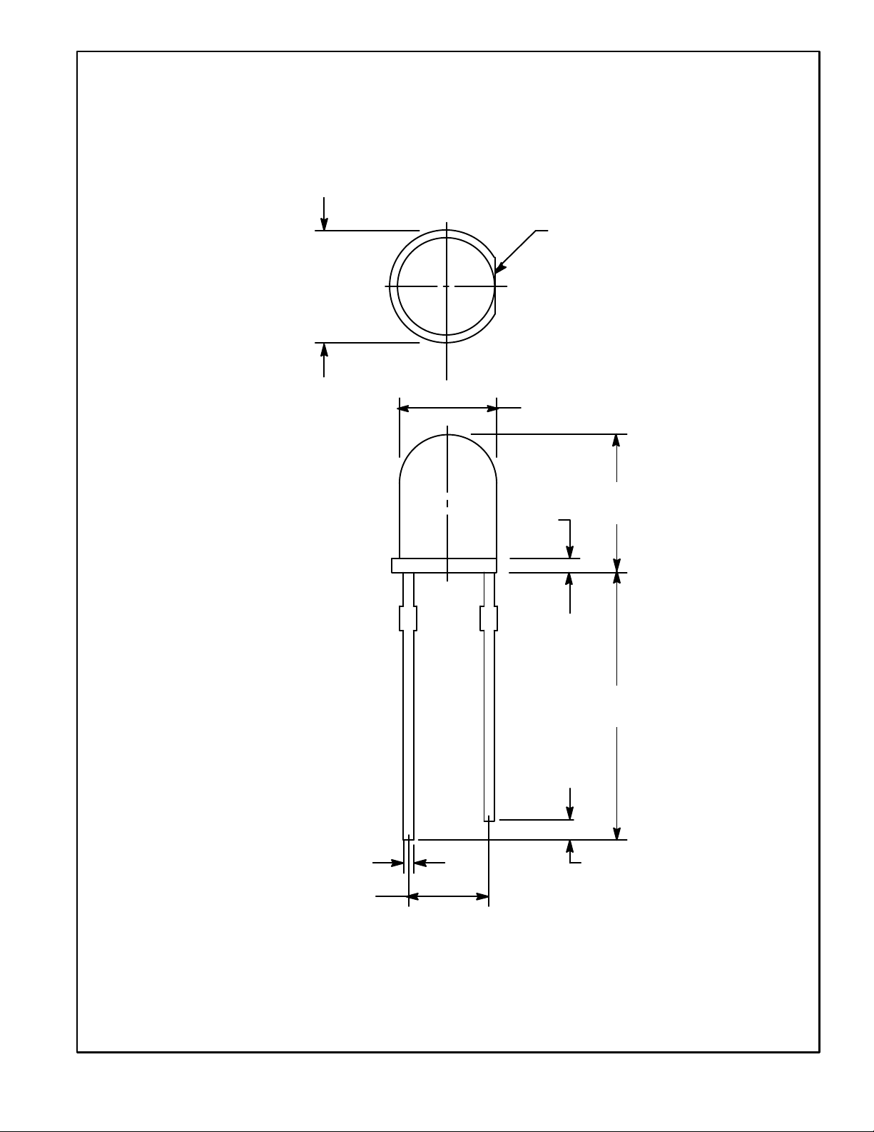
.362
(9.2)
Dia
Flat Denotes
Cathode
.307 (7.8) Dia
.433
(11.0)
.078
(2.0)
.019 (0.5)
.100 (2.54)
1.063
(27.0)
.078 (2.0) Min
 Loading...