

Page 1
This device has been replaced by NTE30128
NTE30122
LED Indicator
Ultraviolet, 5mm
Features:
D High Intensity
D Normal T−1 3/4 (5mm) Diameter Package
D General Purpose Leads
D Reliable and Rugged
Applications:
D Identifies Counterfeit U.S. Currency
D Identification of UV Watermark on Credit Cards, Drivers Licenses, Passports, etc.
D UV Illumination of Detailed Seals, Stamps, Stickers, Images, and Multicolored Fibers on Visas,
Passports and Currencies of Various Nations
Absolute Maximum Ratings: (TA = +25°C unless otherwise specified)
Power Dissipation, P
D
Peak Forward Current (1/10th Duty Cycle, 0.1ms Pulse Width), I
Continuous Forward Current, I
F
FM
120mW. . . . . . . . . . . . . . . . . . . . . . . . . . . . . . . . . . . . . . . . . . . . . . . . . . . . . . . . . .
150mA. . . . . . . . . . . . . . . . . . . .
35mA. . . . . . . . . . . . . . . . . . . . . . . . . . . . . . . . . . . . . . . . . . . . . . . . . . . .
Derate Linearly From +50°C 0.4mA/°C. . . . . . . . . . . . . . . . . . . . . . . . . . . . . . . . . . . . . . . . . . . . . .
Reverse Voltage, V
Operating Temperature Range, T
Storage Temperature Range, T
R
opr
stg
Lead Temperature (During Soldering, 4mm from Body, 5sec Max), T
−40° to +80°C. . . . . . . . . . . . . . . . . . . . . . . . . . . . . . . . . . . . . . . . .
−40° to +80°C. . . . . . . . . . . . . . . . . . . . . . . . . . . . . . . . . . . . . . . . . . .
L
5V. . . . . . . . . . . . . . . . . . . . . . . . . . . . . . . . . . . . . . . . . . . . . . . . . . . . . . . . . . . . . . . . .
+260°C. . . . . . . . . . . . . . . . . .
CAUTION: UV light can be harmful to the eyes even for a brief period. If it is necessary to view UV
light, filtered glasses must be used. Affix a caution label if the UV light in your product can
be viewed directly.
Electrical Optical Characteristics: (TA = +25°C unless otherwise specified)
Parameter Symbol Test Conditions Min Typ Max Unit
Luminous Intensity I
View Angle of Half Power 2 q
Peak Emission Wavelength λ
Dominant Emission Wavelength λ
Spectral Line Half−Width Δλ IF = 20mA − 25 − nm
IF = 20mA, Note 1 60 − 90 mcd
V
Note 2 10 15 20 deg
1/2
IF = 20mA − − − nm
P
IF = 20mA, Note 3 380 − 385 nm
d
Forward Voltage V
Reverse Current I
IF = 20mA 3.0 3.3 3.7 V
F
VR = 5V − − 10 μA
R
Note 1. Luminous intensity is measured with a light sensor and filter combination that approximates
the CIE eye−response curve.
Note 2. q
Note 3. The dominant wavelength (λ
is the off−axis angle at which the luminous intensity is half the axial luminous intensity.
1/2
) is derived from the CIE chromaticity diagram and represents
d
the single wavelenght, which defines the color of the device.
Page 2
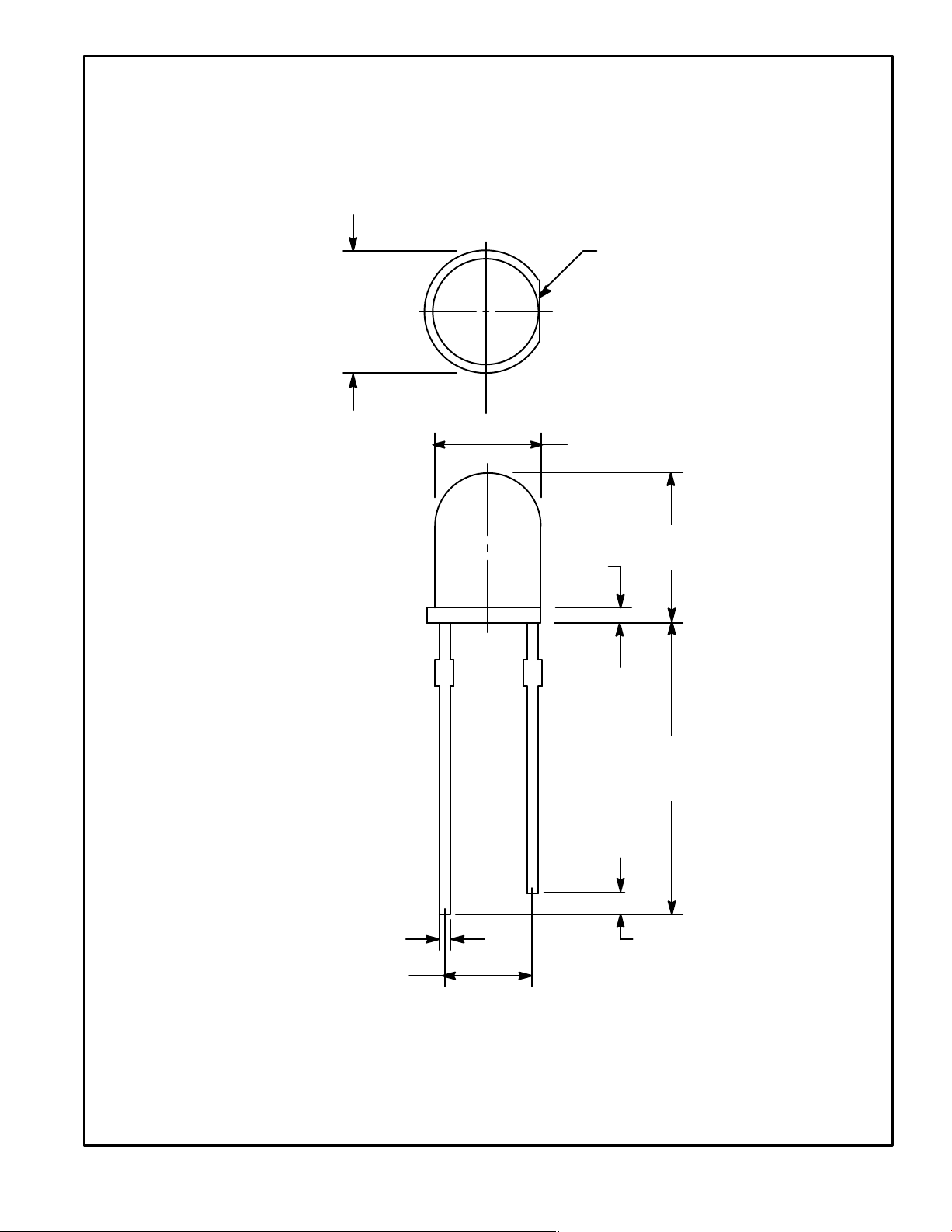
.228
(5.8)
Dia
Flat Denotes
Cathode
.196 (4.98) Dia
.339
(8.6)
.039
(1.0)
.019 (0.5)
.100 (2.54)
1.040
(26.4)
Min
.040 (1.0) Min
 Loading...