

NTE NTE999 Datasheet

NTE999
Integrated Circuit
Adjustable Precision Shunt Regulator
Description:
The NTE999 is a three–terminal adjustable shunt regulator with guaranteed thermal stability over a
temperature range of –0° to +70°C. The output voltage may be set to any value between V
mately 2.5V) and 36V with two external resistors. This device has a typical dynamic output impedance of 0 . 2 Ω. Active output circuitry provides a very sharp turn–on characteristic, making the NTE999
an excellent replacement for zener diodes in many applications.
Features:
D Equivalent Full–Range Temperature Coefficient: 30ppm/°C Typ
D Adjustable Output Voltage
D Fast Turn–On Response
D Sink Current Capability: 1mA to 100mA
D Low Dynamic Output Impedance: 0.2Ω Ty p
D Low Output Noise Voltage
(approxi-
ref
Absolute Maximum Ratings:
Cathode Voltage (Note 1), V
Continuous Cathode Current Range, I
Reference Input Current Range, I
Continuous Power Dissipation, P
(TA = 0° to +70°C unless otherwise specified)
KA
K
ref
D
–100mA to 150mA. . . . . . . . . . . . . . . . . . . . . . . . . . . . . . . . . .
–50µA to 10mA. . . . . . . . . . . . . . . . . . . . . . . . . . . . . . . . . . . . . . . . .
Up to +25°C 775mW. . . . . . . . . . . . . . . . . . . . . . . . . . . . . . . . . . . . . . . . . . . . . . . . . . . . . . . . . . . . .
Derate Above +25°C 6.2mW/°C. . . . . . . . . . . . . . . . . . . . . . . . . . . . . . . . . . . . . . . . . . . . . . . . . . . .
Operating Ambient Temperature Range, T
Storage Temperature Range, T
stg
opr
Lead Soldering Temperature (.0625 (1.6mm) from case for 10s), T
L
0° to +70°C. . . . . . . . . . . . . . . . . . . . . . . . . . . . . . . . . . . .
–65° to +150°C. . . . . . . . . . . . . . . . . . . . . . . . . . . . . . . . . . . . . . . . . .
Recommended Operating Conditions:
Cathode Voltage, V
Min V
. . . . . . . . . . . . . . . . . . . . . . . . . . . . . . . . . . . . . . . . . . . . . . . . . . . . . . . . . . . . . . . . . . . . . . . . .
KA
Max 36V. . . . . . . . . . . . . . . . . . . . . . . . . . . . . . . . . . . . . . . . . . . . . . . . . . . . . . . . . . . . . . . . . . . . . . . .
Cathode Current (For Regulation), I
K
Min 1mA. . . . . . . . . . . . . . . . . . . . . . . . . . . . . . . . . . . . . . . . . . . . . . . . . . . . . . . . . . . . . . . . . . . . . . . .
Max 100mA. . . . . . . . . . . . . . . . . . . . . . . . . . . . . . . . . . . . . . . . . . . . . . . . . . . . . . . . . . . . . . . . . . . . .
Note 1. Voltage values are with respect to the anode terminal unless otherwise specified.
37V. . . . . . . . . . . . . . . . . . . . . . . . . . . . . . . . . . . . . . . . . . . . . . . . . . . . . . .
260°C. . . . . . . . . . . . . . . . . . . . .
ref
Electrical Characteristics: (TA = 25°C unless otherwise specified)
∆
Parameter Symbol Test Conditions Min Typ Max Unit
Reference Input Voltage V
Deviation of Reference Input
V
ref(dev)VKA
Voltage
Ratio of Change in Reference ∆V
Input Voltage to the Change in
V
ref
ref
KA
VKA = V
= V
= 0° to +70°C
T
A
IK = 10mA
Cathode Voltage
Reference Input Current I
Deviation of Reference Input
I
ref(dev)IK
Current
Minimum Cathode Current for
I
min
ref
IK = 10mA, R1 = 10kΩ, R2 = ∞ – 2.0 4.0 µA
= 10mA, R1 = 10kΩ, R2 = ∞
= 0° to +70°C
T
A
VKA = V
Regulation
Off–State Cathode Current I
off
VKA = 36V, V
Dynamic Impedance |zak| VKA = V
f ≤ 1kHz
.210
(5.33)
Max
, IK = 10mA 2440 2495 2550 mV
ref
, IK = 10mA,
ref
∆VKA = 10V–V
ref
– 8 17 mV
– –1.4 –2.7 mV
∆VKA = 36V–10V – –1.0 –2.0 V
– 0.4 1.2 µA
ref
= 0 – 0.1 1.0 µA
ref
, IK = 1mA to 100mA
ref
– 0.4 1.0 mA
– 0.2 0.5 Ω
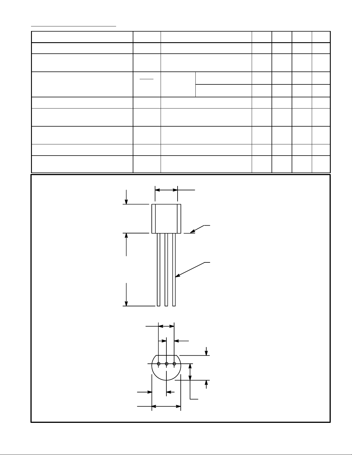
.135 (3.45) Min
Seating Plane
.500
(12.7)
Min
.100 (2.54)
.105 (2.67) Max
.205 (5.2) Max
.021 (.445) Dia Max
Ref K
A
.050 (1.27)
.165
(4.2)
Max
.105 (2.67) Max
 Loading...