

NTE NTE879 Datasheet
NTE879
Integrated Circuit
RGB to PAL/NTSC Encoder for Color TV
Description:
The NTE879 is an integrated circuit in a 20–Lead DIP type package used to generate a composite
TV signal from baseband red, blue, green, and sync inputs. This device has color subcarrier oscillator,
voltage controlled 90° phase shifter , two DSB suppressed carrier chroma modulators, RGB input matrices, and blanking level clamps. It can be operated with very few external parts, but has the pin–outs
for a fully implemented, top quality composite signal. It is ideal for encoding signals from color cameras and graphic generators.
Features:
D Reference Oscillator Self–Contained or Externally Driven
D Nominal 90° ±5° Axes are Optionally Trimmable
D Simple PAL/NTSC Switch
D Luminance and Chroma Channels can accept Delay Line/Bandpass Elements or Direct Con-
nection
D Provides DC Reference to Permit Direct Drive to RF Modulator
Absolute Maximum Ratings:
Supply Voltage, V
8.2Vdc Regulator Output Current, I
Power Dissipation, P
CC
REG
D
10mA. . . . . . . . . . . . . . . . . . . . . . . . . . . . . . . . . . . . . . . . . . . . . .
1.25W. . . . . . . . . . . . . . . . . . . . . . . . . . . . . . . . . . . . . . . . . . . . . . . . . . . . . . . . . . . .
Derate Above 25°C 10mW/°C. . . . . . . . . . . . . . . . . . . . . . . . . . . . . . . . . . . . . . . . . . . . . . . . . . . . . .
Junction Temperature, T
J
Operating Temperature Range, T
Storage Temperature Range, T
stg
A
–65° to +150°C. . . . . . . . . . . . . . . . . . . . . . . . . . . . . . . . . . . . . . . . . .
+150°C. . . . . . . . . . . . . . . . . . . . . . . . . . . . . . . . . . . . . . . . . . . . . . . . . . . . . . . . .
0° to +70°C. . . . . . . . . . . . . . . . . . . . . . . . . . . . . . . . . . . . . . . . . . . . .
Recommended Operating Conditions:
Supply Voltage, V
CC
12 ±2V. . . . . . . . . . . . . . . . . . . . . . . . . . . . . . . . . . . . . . . . . . . . . . . . . . . . . . . . . . . . .
Sync Tip Level –0.5 to +1.0V. . . . . . . . . . . . . . . . . . . . . . . . . . . . . . . . . . . . . . . . . . . . . . . . . . . . . . . . . . . .
Sync, Blanking Level +1.7 to +8.2V. . . . . . . . . . . . . . . . . . . . . . . . . . . . . . . . . . . . . . . . . . . . . . . . . . . . . .
Reg, Green, Blue Inputs (Saturated) 1V
. . . . . . . . . . . . . . . . . . . . . . . . . . . . . . . . . . . . . . . . . . . . . . . .
15V. . . . . . . . . . . . . . . . . . . . . . . . . . . . . . . . . . . . . . . . . . . . . . . . . . . . . . . . . . . . . . . .
P–P
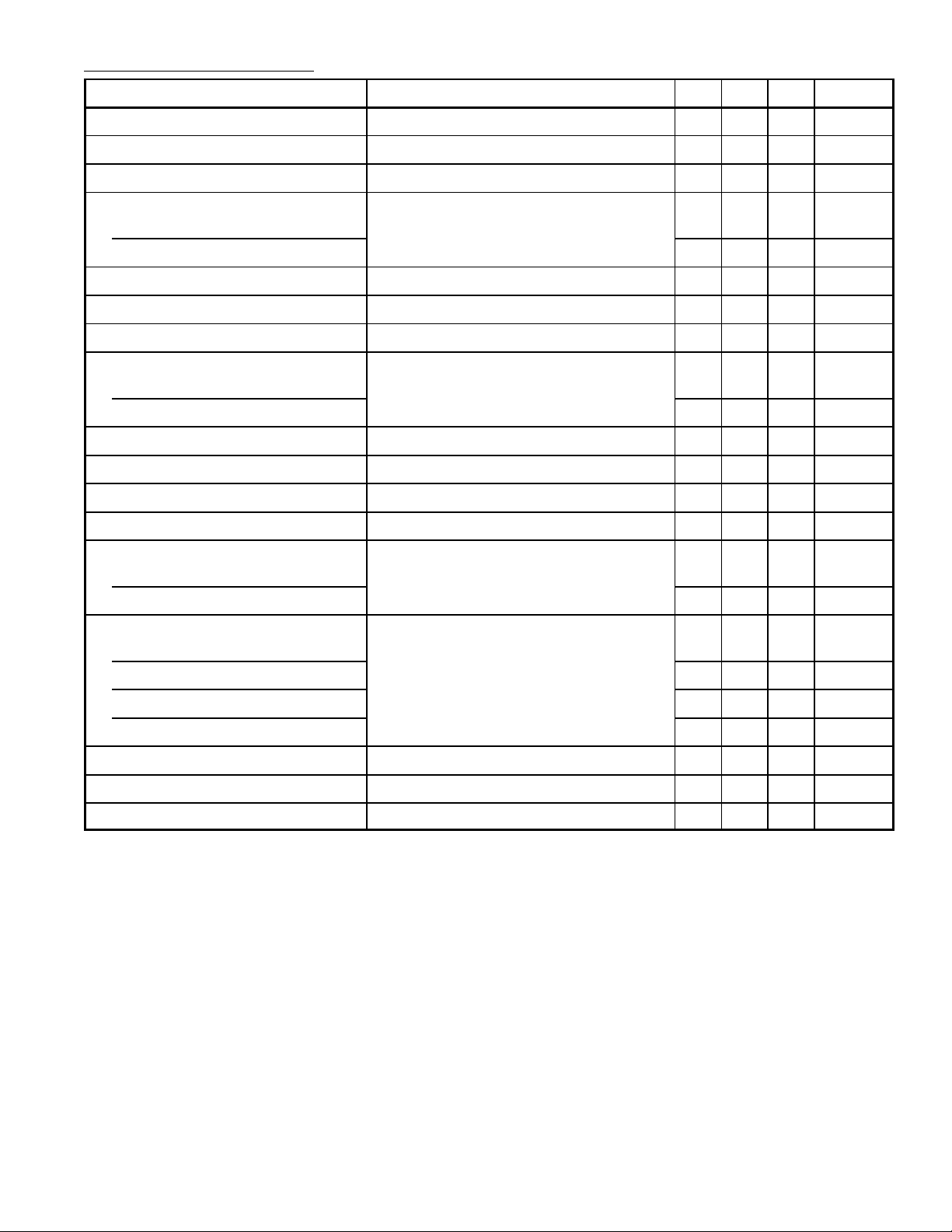
Electrical Characteristics: (VCC = 12V, TA = +25°C unless otherwise specifed)
Parameter Pin Number/Test Conditions Min Typ Max Unit
Supply Current Pin14 – 32 – mA
Oscillator Amplitude Pin18 – 0.5 – V
External Subcarrier Input Oscillator Components Removed, Pin17 – 0.25 – V
Subcarrier Input
Resistance
Pin17
– 5.0 – kΩ
P–P
RMS
Capacitance – 2.0 – pF
Modulation Angle (R–Y) to (B–Y) 85 90 95 Degrees
Angle Adjustment (R–Y), Pin19 – 0.25 – Deg/µA
R, G, B Input 100% Color Saturation Pin3, Pin4, Pin5 0.95 1.0 1.05 V
R, G, B Input
Resistance
Pin3, Pin4, Pin5
– 10 – kΩ
P–P
Capacitance – 2.0 – pF
Sync Threshold Pin2 – 1.7 – V
Sync Input Resistance Input > 1.7V, Pin2 – 10 – kΩ
Chroma Output Level 100% Saturation. Pin13 – 1.0 – V
P–P
Chroma Output Resistance Pin13 – – 80 Ω
Chroma Input
Resistance
Pin10
– 10 – kΩ
Capacitance – 2.0 – pF
Composite Output
Sync
Luminance – 1.4 – V
Chroma – 1.7 – V
Burst – 0.6 – V
100% Saturation, Pin9
– 0.6 – V
P–P
P–P
P–P
P–P
Output Impedance Pin9, Note 1 – – 100 Ω
Luminance Bandwidth 3dB, Less Delay Line, Pin9 – 8.0 – MHz
Subcarrier Leakage in Output Pin9 – – 40 mV
P–P
Note 1. Output impedance can be reduced to less than 10Ω by using a 150Ω output load from Pin9
to GND. Power supply current will increase to about 60mA.
 Loading...