

NTE NTE860 Datasheet
NTE860
Integrated Circuit
Low–Power, Narrow–Band FM IF
Description:
The NTE860 is an integrated circuit in an 18–Lead DIP type package which includes an oscillator,
mixer, limiting amp, AFC, quadrature discriminator, op/amp, squelch, scan control and mute switch.
Absolute Maximum Ratings:
Power Supply Voltage, V
Operating Supply Voltage Range, V
Input Voltage (V
Mute Function, V
≥ 6.0 Volts), V
CC
. . . . . . . . . . . . . . . . . . . . . . . . . . . . . . . . . . . . . . . . . . . . . . . . . . . . . . . .
16
Operating Junction Temperature, T
Operating Ambient Temperature Range, T
Storage Temperature Range, T
Electrical Characteristics:
Parameter Test Conditions Min Typ Max Unit
Drain Current (Pin4 & Pin8) Squelch OFF – 3.6 6.0 mA
Input for 20dB Quieting – 8.0 – µA
Input for –3dB Limiting – 2.0 – µA
Mixer Voltage Gain Pin18 to Pin3, Open – 46 –
Mixer Third Order Intercept 50Ω Input – –1.0 – dBm
Mixer Input Capacitance – 2.2 – pF
(TA = +25°C, unless otherwise specified)
(max) 12V. . . . . . . . . . . . . . . . . . . . . . . . . . . . . . . . . . . . . . . . . . . . . . . . . . . . .
CC
CC
. . . . . . . . . . . . . . . . . . . . . . . . . . . . . . . . . . . . . . . . . . . . . . . .
18
–0.7 to 12V
J
A
stg
(VCC = 6V, fo = 10.7MHz, ∆f = ±3.0kHz, f
T
= +25°C unless otherwise noted)
A
Squelch ON – 5.4 7.0 mA
= 1.0kHz, 50Ω source,
mod
–30° to +70°C. . . . . . . . . . . . . . . . . . . . . . . . . . . . . . . . . . .
–65° to +150°C. . . . . . . . . . . . . . . . . . . . . . . . . . . . . . . . . . . . . . . . . .
4V to 9V. . . . . . . . . . . . . . . . . . . . . . . . . . . . . . . . . . . . . . . . . . . .
1.0V
+150°C. . . . . . . . . . . . . . . . . . . . . . . . . . . . . . . . . . . . . . . . . . . . . . .
rms
pk
rms
rms
Recovered Audio, Pin10 Input Signal 1.0mV
Detector Center Frequency Slope, Pin10 – 0.3 – V/kHz
AFC Center Slope, Pin11 Unloaded – 12 – V/kHz
Filter Gain 40 51 – dB
Squelch Threshold Through 10K to Pin14 – 0.01 1.0 µA
Scan Control Current, Pin15 Pin14 High – 0.01 1.0 µA
Pin14 Low 2.0 2.4 – mA
Mute Switch Impedance Pin14 High – 5.0 – MΩ
Pin14 Low – 1.5 – MΩ
rms
450 700 – mV
rms
Pin Connection Diagram
Crystal OSC
Crystal OSC
Mixer Output
1
2
3
V
4
CC
5Limiter Input
6Decoupling
7Decoupling
8Quadrature Input
9Demodulator Filter 10
18 10
RF Input
18
17
GND
Audio Mute
16
15
Scan Control
14 Squelch Input
13 Filter Output
Filter Input
12
11
Demodulator Output
Recovered Audio
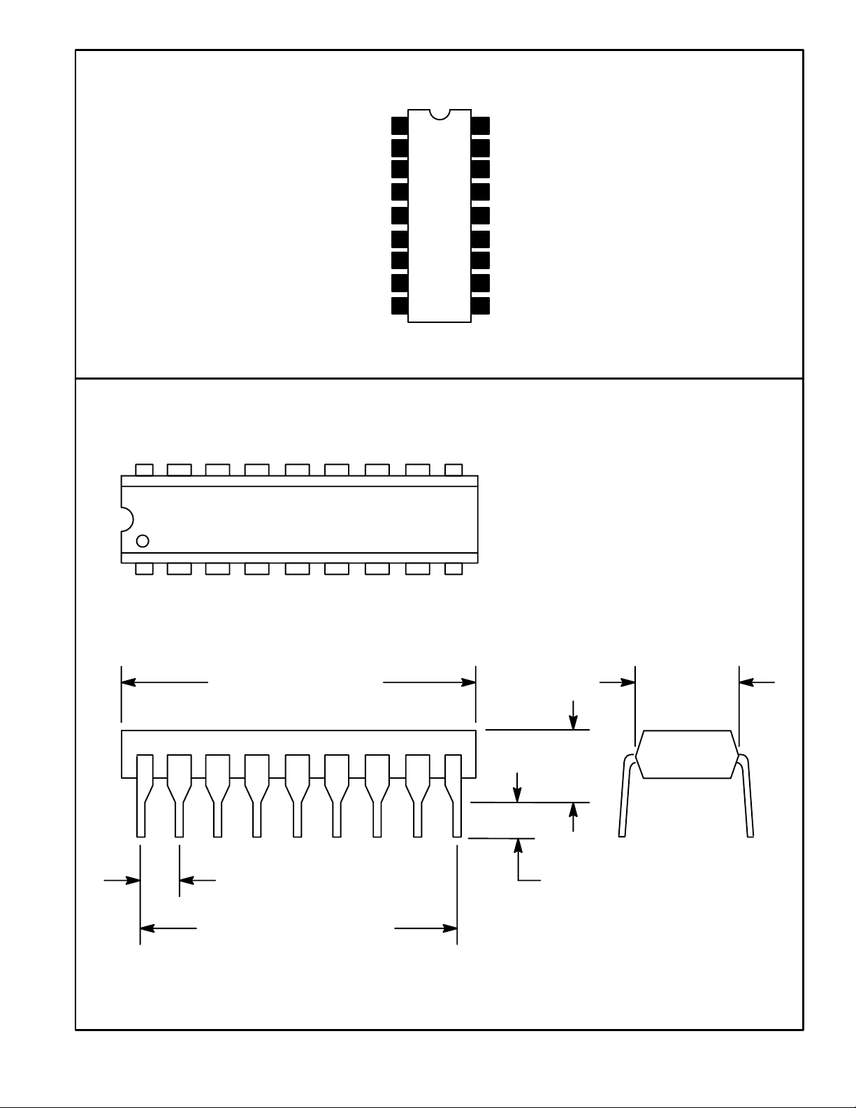
19
.870 (22.1) Max
.250 (6.35)
.150
(3.8)
.100 (2.54) .125 (3.17) Min
.800 (20.3)
 Loading...