

NTE NTE856 Datasheet

NTE856
Integrated Circuit
TV Video Modulation Circuit
Description:
The NTE856 is an RF oscillator and dual–input modulator in an 8–Lead DIP type package designed
to generate a TV signal from baseband video inputs. Typical applications include video games, home
computer display, video recorders, and test equipment.
The very low level of intermodulation products, compact package and small external component
count make this device superior to simple discrete circuits.
Features:
D Single 5V Supply
D Channel 3 or 4 Operation
D Excellent Oscillator Stability to 100MHz
D Color and Sound Compatibility
D Dual Input Modulator for Ease of Signal
D Low Intermodulation (–50dB 920kHz Beat)
D Overmodulation Protection
Absolute Maximum Ratings:
Supply Voltage 8V. . . . . . . . . . . . . . . . . . . . . . . . . . . . . . . . . . . . . . . . . . . . . . . . . . . . . . . . . . . . . . . . . . . . . .
Power Dissipation Package 1.25W. . . . . . . . . . . . . . . . . . . . . . . . . . . . . . . . . . . . . . . . . . . . . . . . . . . . . . . .
Derate above 25°C 13mW/°C. . . . . . . . . . . . . . . . . . . . . . . . . . . . . . . . . . . . . . . . . . . . . . . . . . . . . .
Junction Temperature +150°C. . . . . . . . . . . . . . . . . . . . . . . . . . . . . . . . . . . . . . . . . . . . . . . . . . . . . . . . . . . .
Operating Ambient Temperature Range 0° to +70°C. . . . . . . . . . . . . . . . . . . . . . . . . . . . . . . . . . . . . . . .
Storage Temperature Range –65° to +150°C. . . . . . . . . . . . . . . . . . . . . . . . . . . . . . . . . . . . . . . . . . . . . . .
Recommended Operating Conditions:
Supply Voltage 5V. . . . . . . . . . . . . . . . . . . . . . . . . . . . . . . . . . . . . . . . . . . . . . . . . . . . . . . . . . . . . . . . . . . . . .
Luma Input Voltage
Sync Tip 1V. . . . . . . . . . . . . . . . . . . . . . . . . . . . . . . . . . . . . . . . . . . . . . . . . . . . . . . . . . . . . . . . . . . . .
Peak White 0.35V. . . . . . . . . . . . . . . . . . . . . . . . . . . . . . . . . . . . . . . . . . . . . . . . . . . . . . . . . . . . . . . .
Electrical Characteristics: (VCC = 5V, TA = +25°C unless otherwise specified)
Parameter Test Conditions Min Typ Max Unit
Operating Supply Voltage 4.75 5.0 5.25 V
Supply Current – 12 – mA
RF Modultor
Luma Input Dynamic Range (Pin4) 0 – 1.5 V
RF Output Voltage f = 67.25MHz, V4 = 1V – 15 – mV
Luma Conversion Gain ∆V7/∆V4, V4 = 0.1V to 1V – 0.8 – V/V
Chroma Conversion Gain ∆V7/∆V5, V5 = 1.5V
Chroma Linearity (Pin7) V5 = 1.5V
Luma Linearity (Pin7) V4 = 0 to 1.5V – 2.0 – %
Input Current (Pin4) – – –20 µA
Input Resistance (Pin5) – 800 – Ω
Input Resistance (Pin4) 100 – – kΩ
Input Capacitance (Pin4, Pin5) – – 5.0 pF
Residual 920kHz Measured at Pin7, Note 1 – 60 – dB
Output Current (Pin7) V4 = 0 – 1.5 – mA
Temperature Characteristics (VCC = 7V, TA = 0° to +70°C, IC only)
RF Oscillator Deviation fo = 67.265MHz
P–P
, V4 = 1V – 0.95 – V/V
P–P
– 1.0 – %
Note 1. RF Reference Level = 6.0mV at Pin7. Load Impedance = 75Ω.
RF + 4.5MHz = –13dB.
RF + 3.58MHz = –20dB.
rms
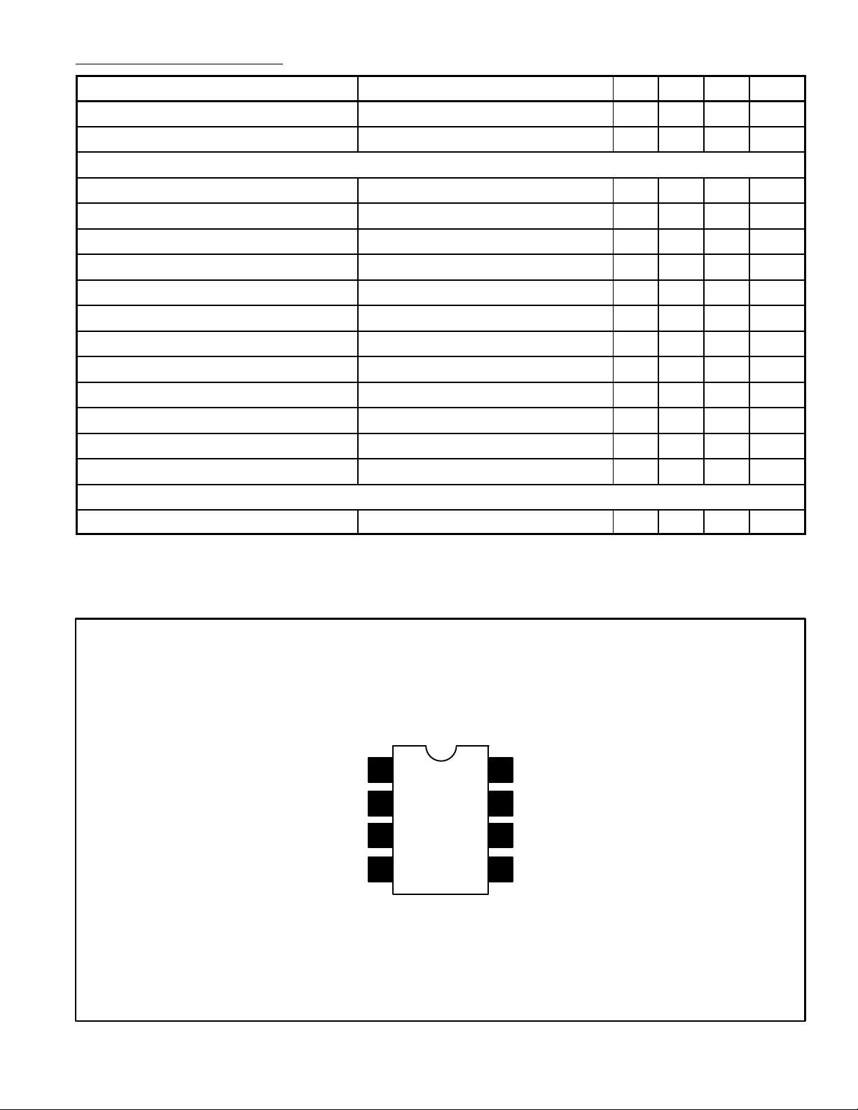
RF Tank
RF Tank
GND
Video Input
Pin Connection Diagram
1
2
3
4
8
7
6
5
N.C.
RF Output
V
CC
Sound/Chroma Input
 Loading...