

NTE NTE853 Datasheet
NTE853
Integrated Circuit
Low Power, Narrow Band, FM IF System
Description:
The NTE853 is a low power narrow band FM IF system which includes: Oscillator, Mixer, Limiting
Amplifier, Quadrature Discriminator, Active Filter, Squelch, Scan Control and Mute Switch. The
NTE853 is designed for use in FM dual conversion communications equipment.
Features:
D Low Drain Current (3mA Typ @ VCC = 6V)
D Excellent Sensitivity: Input Limiting Voltage (–3.0dB) = 5.0µV (Typ)
D Low Number of External Parts Required
Absolute Maximum Ratings: (TA = +25°C, unless otherwise specified)
Power Supply Voltage (Pin4), VCC(max) 12V. . . . . . . . . . . . . . . . . . . . . . . . . . . . . . . . . . . . . . . . . . . . . . .
Operating Supply Voltage Range (Pin4), V
Detector Input Voltage (Pin8), 1V
Input Voltage (V
Mute Function (Pin14), V
≥ 6V, Pin16), V
CC
14
Operating Junction Temperature, T
. . . . . . . . . . . . . . . . . . . . . . . . . . . . . . . . . . . . . . . . . . . . . . . . . . . . .
16
. . . . . . . . . . . . . . . . . . . . . . . . . . . . . . . . . . . . . . . . . . . . . . . . .
J
Operating Ambient Temperature Range, T
Storage Temperature Range, T
stg
CC
. . . . . . . . . . . . . . . . . . . . . . . . . . . . . . . . . . . . . . . . . . . . . . .
A
–65° to +150°C. . . . . . . . . . . . . . . . . . . . . . . . . . . . . . . . . . . . . . . . . .
4V to 8V. . . . . . . . . . . . . . . . . . . . . . . . . . . . . . . . . . . . . .
1V
–0.5V to 5V
+150°C. . . . . . . . . . . . . . . . . . . . . . . . . . . . . . . . . . . . . . . . . . . . . . .
–30° to +70°C. . . . . . . . . . . . . . . . . . . . . . . . . . . . . . . . . . .
p–p
RMS
pk
Electrical Characteristics:
(VCC = 6V, fO = 10.7MHz, ∆f = ± 3kHz, f
= 1kHz, TA = +25°C
mod
unless otherwise specified)
Parameter Pin Test Conditions Min Typ Max Unit
Drain Current, Squelch OFF 4 – 2 – mA
Drain Current, Squelch ON 4 – 3 5 mA
Input Limiting Voltage 16 –3dB Limiting – 5 10 µV
Detector Output Voltage 9 – 3 – V
Detector Output Impedance – – 400 – Ω
Recovered Audio Output Voltage 9 Vin = 10mV 200 350 – mV
rms
Electrical Characteristics (Cont’d): (VCC = 6V, fO = 10.7MHz, ∆f = ± 3kHz, f
= 1kHz, TA = +25°C
mod
unless otherwise specified)
Parameter Pin Test Conditions Min Typ Max Unit
Filter Gain – Vin = 10mV, 10kHz 40 46 – dB
Filter Output Voltage 11 1.8 2.0 2.5 V
Trigger Hysteresis – – 100 – mV
Mute Function, LOW 14 – 15 50 Ω
Mute Function, HIGH 14 1 10 – MΩ
Scan Function, LOW 13 Mute OFF, V12 = 2V – 0 0.5 V
Scan Function, HIGH 13 Mute ON, V12 = GND 5.0 – – V
Mixer Conversion Gain 3 – 20 – dB
Mixer Input Resistance 16 – 3.3 – kΩ
Mixer Input Capacitance 16 – 2.2 – pF
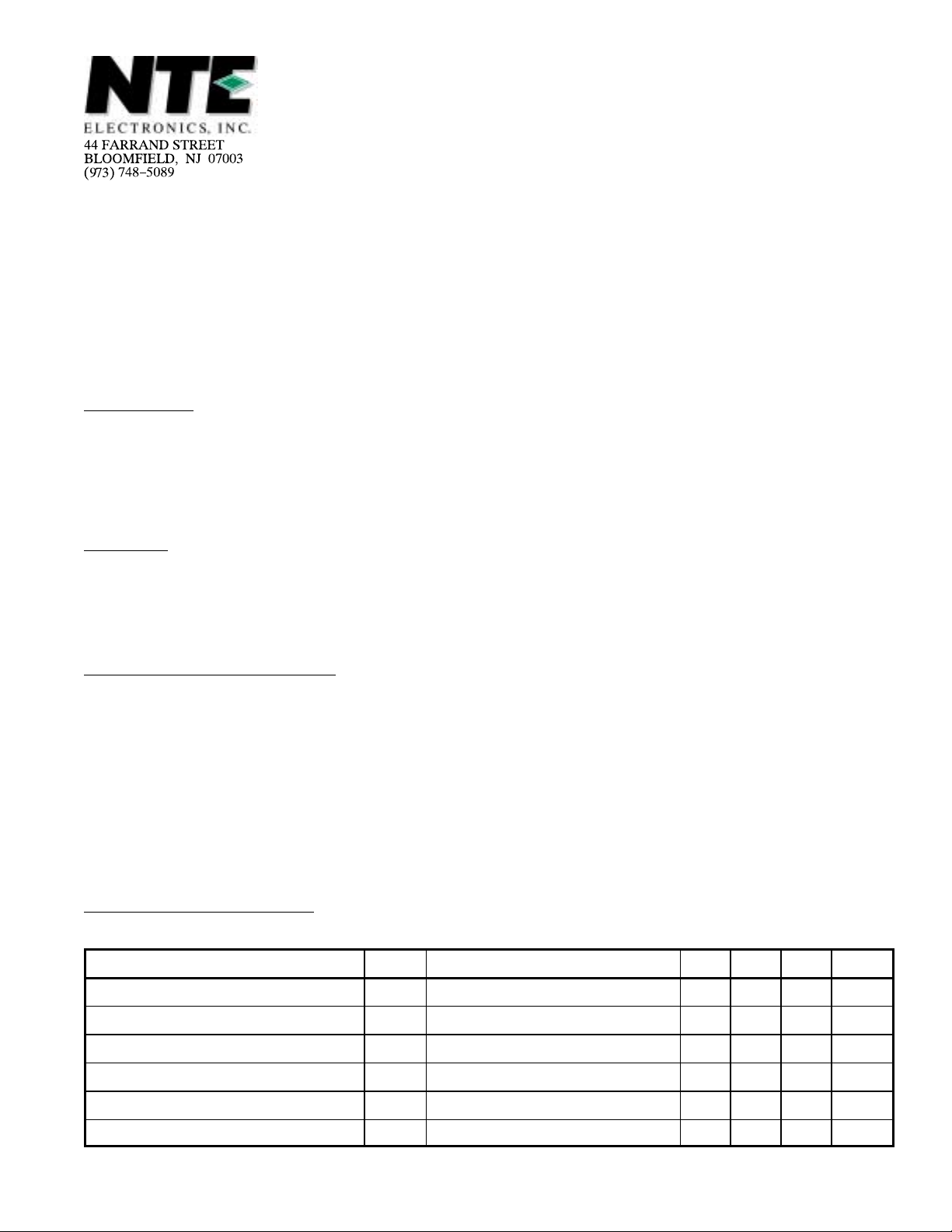
Pin Connection Diagram
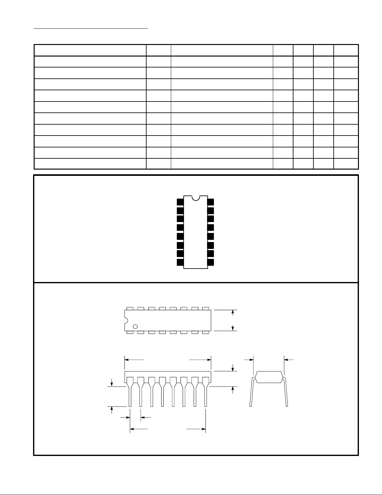
.245
(6.22)
Min
V
Max
CC
1
2
3
4
5Limiter Input
6Decoupling
7Limiter Output
8Quad Input
Crystal OSC
Crystal OSC
Mixer Output
16 9
18
.785 (19.9)
16
RF Input
15
GND
14
Audio Mute
13
Scan Control
Squelch Input
12
11 Filter Output
Filter Input
10
Demodulator Output
9
.260 (6.6) Max
.200 (5.08)
Max
.300
(7.62)
.100 (2.54)
.700 (17.7)
 Loading...