

NTE NTE8374 Datasheet
NTE8374
Integrated Circuit
Seven–Segment Latch/Decoder/Driver for Common Anode LED’s
Description:
The NTE 8374 is a 7–segment decoder driver in a 16–Lead DIP type package incorporating input
latches and output circuits to directly drive common anode LED displays.
Features:
D High speed input latches for data storage
D 15mA constant current sink capability to directly drive common anode led displays
D Increases incandescent display life
D Active low latch enable for easy interface with MSI circuits
D Data input loading essentially zero when latch disabled
D Automatic ripple blanking for suppression of leading and/or trailing–edge zeroes.
Input Loading/Fan–Out:
Description Pin Name High Low
Address (Data) Inputs, A0 – A
Latch Enable Input (Active LOW) L
Ripple Blanking Input (Active LOW) RBI 0.5 0.25
Ripple Blanking as Output (Active LOW) RBO 1.0 0.5
Ripple Blanking as Input (Active LOW) RBO – 0.75
Constant Current Outputs (Active LOW) a – g Open Collector 15mA
3
E
1.0 0.25 (Note 1)
0.5 0.25
Note 1. Except Loading is 10µA @ 0.4V when LE is HIGH.
Absolute Maximum Ratings:
Input Voltage –0.5V to +5.5V. . . . . . . . . . . . . . . . . . . . . . . . . . . . . . . . . . . . . . . . . . . . . . . . . . . . . . . . . . . .
Input Current –30mA to +5.0mA. . . . . . . . . . . . . . . . . . . . . . . . . . . . . . . . . . . . . . . . . . . . . . . . . . . . . . . . .
Voltage Applied to Outputs in HIGH State:
Standard TTL –0.5V to VCC value. . . . . . . . . . . . . . . . . . . . . . . . . . . . . . . . . . . . . . . . . . . . . . . . . .
Open Collector –0.5V to +7.0V. . . . . . . . . . . . . . . . . . . . . . . . . . . . . . . . . . . . . . . . . . . . . . . . . . . . .
VCC Pin Potential to GND Pin –0.5V to +7.0V. . . . . . . . . . . . . . . . . . . . . . . . . . . . . . . . . . . . . . . . . . . . . .
Current Applied to Output in LOW State (Max) twice the rated I
Storage Temperature Range –65° to +150°C. . . . . . . . . . . . . . . . . . . . . . . . . . . . . . . . . . . . . . . . . . . . . . .
Ambient Temperature Range Under Bias –55° to +125°C. . . . . . . . . . . . . . . . . . . . . . . . . . . . . . . . . . . .
Junction Temperature Range Under Bias –55° to +175°C. . . . . . . . . . . . . . . . . . . . . . . . . . . . . . . . . . .
Recommended Operating Conditions:
Supply Voltage +4.75V to +5.25V. . . . . . . . . . . . . . . . . . . . . . . . . . . . . . . . . . . . . . . . . . . . . . . . . . . . . . . . .
Free Air Ambient Temperature 0°C to +70°C. . . . . . . . . . . . . . . . . . . . . . . . . . . . . . . . . . . . . . . . . . . . . .
. . . . . . . . . . . . . . . . . . . . . . . . . . . .
OL
Functional Description:
The NTE8374 is a 7–segment decoder/driver with latches on the address inputs and active LOW
constant current outputs to drive LEDs directly . This device accepts a 4–bit binary code and produces
output drive to the appropriate segments of the 7–segment display . It has a decode format which produces numeric codes “0” through “9” and other codes.
Latches on the four data inputs are controlled by an active LOW Latch Enable, LE. When LE is LOW ,
the state of the outputs is determined by the input data. When LE goes HIGH, the last data present
at the inputs is stored in the latches and the outputs remain stable. The LE pulse width necessary
to accept and store data can be routed directly from high speed counters and frequency dividers into
the display without slowing down the system clock or providing intermediate data storage.
The latch/decoder combination is a simple system which drives LED displays with multiplexed data
input from MOS time clocks, DVMs, calculator chips, etc. Data inputs are multiplexed while the displays are in static mode. This lowers component and insertion costs, since several circuits–seven
resistors per display, strobe drivers, a separate display voltage source, and clock failure detect circuits–traditionally found in multiplexed display systems are eliminated. It also allos low strobing rates
to be used without display flicker.
Another NTE8374 feature is the reduced loading on the data inputs when the Latch Enable is HIGH
(only 10µA typ). This allows many NTE8374s to be driven from a MOS device in multiplex mode without the need for drivers on the data lines. The NTE8374 also provides automatic blanking capability
0060.0300 would be displayed as 60.03. Leading–edge zero suppression is obtained by connecting
the Ripple Blanking Output (RBO) of a decoder to the Ripple Blanking Input (RBI) of the next lower
stage device. The most significant decoder stage should have the RBI input grounded; and since
suppression of the least significant integer zero in a number is not usually desired, the RBI input of
this decoder stage should be left open. A similar procedure for the fractional part of a display will provide automatic suppression of trailing–edge zeros. The RBO terminal of the decoder can be or tied
with a modulating signal via an isolating buffer to achieve duration intensity modulation. A suitable
signal can be generated for this purpose by forming a variable frequency multivibrator with a cross
coupled pair of TTL or DTL gates.
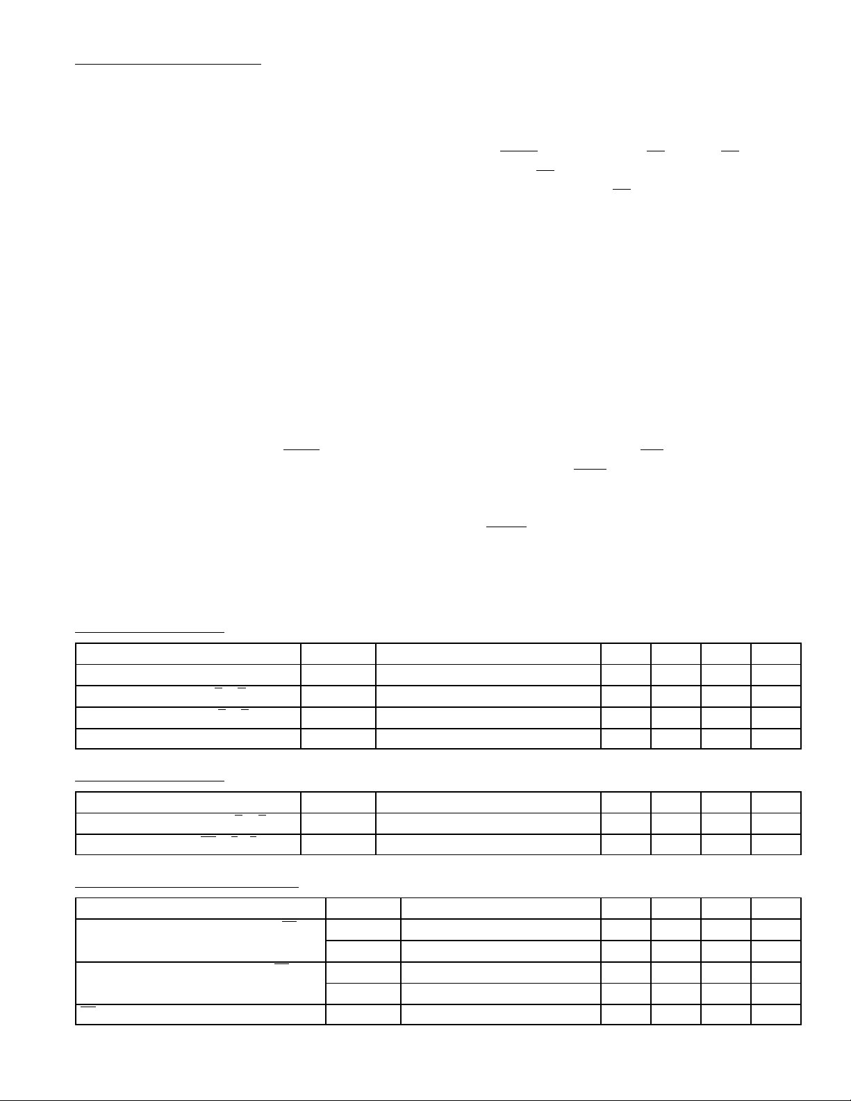
DC Characteristics: (TA = 0 to +70°C unless otherwise specified)
Parameter Symbol Test Conditions Min Typ Max Unit
Output Voltage, Applied (OFF) V
Output LOW Current, a – g I
Output HIGH Current, a – g I
Power Supply Current I
OUT
OL
OH
CC
Separate LED Supply – – 10 V
VCC = 5V, VOL = 3V, TA = +25°C 12 – 18 mA
VCC = Max, V
VCC = Max, VIN = GND, V
= 5.5V – – 250 µA
OUT
= 3V – – 50 mA
OUT
AC Characteristics: (VCC = +5VTA = +25°C unless otherwise specified)
Parameter Symbol Test Conditions Min Typ Max Unit
Propagation Delay, An to a – g t
Propagation Delay, L
E to a – g
PLH
t
PLH
, t
PHLCL
, t
PHLCL
= 15pF, RL = 1kΩ – – 140 ns
= 15pF, RL = 1kΩ – – 140 ns
AC Operating Requirements: (VCC = +5VTA = +25°C unless otherwise specified)
Parameter Symbol Test Conditions Min Typ Max Unit
Setup Time HIGH or LOW, An to L
Hold Time HIGH or LOW, An to L
LE Pulse Width LOW tw (L) 85 – – ns
E
E
ts (H) 75 – – ns
ts (L) 30 – – ns
th (H) 0 – – ns
th (L) 0 – – ns
 Loading...