

NTE NTE836 Datasheet

NTE836
Linear Integrated Circuit
TV Horizontal Processor
Description:
The NTE836 is a TV Horizontal Processor in an 8–Lead DIP type package that includes a phase detector, oscillator and pre–driver. This device is designed for use in all types of television receivers that
have negative flyback inputs.
Features:
D Internal Shunt Regulator
D Preset Hold Control Capability
D ± 300Hz Typical Pull–In
D Linear Balanced Phase Detector
D Variable Output Duty Cycle for Driving Tube or Transistor
D Low Thermal Frequency Drift
D Small Static Phase Error
D Adjustable DC Loop Gain
D Negative Flyback Inputs
Absolute Maximum Ratings: (TA = +25°C, unless otherwise specified)
Supply Current 40mA. . . . . . . . . . . . . . . . . . . . . . . . . . . . . . . . . . . . . . . . . . . . . . . . . . . . . . . . . . . . . . . . . . .
Output Voltage 40V. . . . . . . . . . . . . . . . . . . . . . . . . . . . . . . . . . . . . . . . . . . . . . . . . . . . . . . . . . . . . . . . . . . . .
Output Current 30mA. . . . . . . . . . . . . . . . . . . . . . . . . . . . . . . . . . . . . . . . . . . . . . . . . . . . . . . . . . . . . . . . . . .
Sync Input Voltage (Pin3) 5.0V
Flyback Input Voltage (Pin4) 5.0V
Power Dissipation, P
D
Derate above T
Operating Ambient Temperature Range, T
Storage Temperature Range, T
. . . . . . . . . . . . . . . . . . . . . . . . . . . . . . . . . . . . . . . . . . . . . . . . . . . . . . .
. . . . . . . . . . . . . . . . . . . . . . . . . . . . . . . . . . . . . . . . . . . . . . . . . . . . .
A
opr
stg
625mW. . . . . . . . . . . . . . . . . . . . . . . . . . . . . . . . . . . . . . . . . . . . . . . . . . . . . . . . . . .
5.0mW/°C. . . . . . . . . . . . . . . . . . . . . . . . . . . . . . . . . . . . . . . . . . . . . . . . . . . . . . .
0° to +75°C. . . . . . . . . . . . . . . . . . . . . . . . . . . . . . . . . . . .
–65° to +150°C. . . . . . . . . . . . . . . . . . . . . . . . . . . . . . . . . . . . . . . . . .
(p–p)
(p–p)
Electrical Characteristics: (TA = +25°C unless otherwise specified)
Parameter Test Conditions Min Typ Max Unit
Regulated Voltage (Pin6) 8.0 8.6 9.0 V
Supply Current (Pin6) – 20 – mA
Collector–Emitter Saturation Voltage IC = 20mA, Pin1 – 0.15 0.25 V
Voltage (Pin4) – 2.0 – V
Oscillator Pull–In Range – ±300 – Hz
Oscillator Hold–In Range – ±900 – Hz
Static Phase Error ∆f = 300Hz – 0.5 – µs
Free–Running Frequency Supply Dependence S1 in Position 2 – ±3.0 – Hz/V
Phase Detector Leakage (Pin5) All Switches in Position 2 – – ±1.0 µA
Sync Input Voltage (Pin3) 2.0 – 5.0 V
Sawtooth Input Voltage (Pin4) 1.0 – 3.0 V
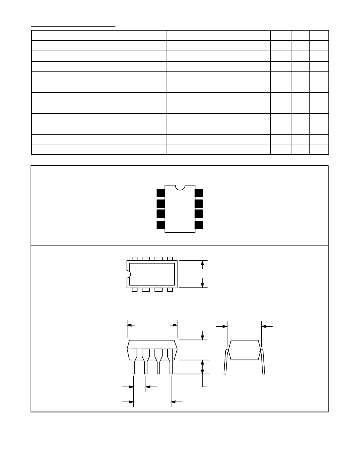
Pin Connection Diagram
Output
GND
Sync Input
Sawtooth Input
85
14
2
3
4
Mark Space Ratio1
8
7
OSC Timing
V
6
CC
Phase Detector Output
5
.256 (6.52) Max
P–P
P–P
.393 (10.0)
Max
.300 (7.62)
.300 (7.62)
.150
(3.81)
.070 (1.77) Min.100 (2.54)
 Loading...