

NTE818
Integrated Circuit
TV Luminance Processor
Features:
D Luma/Chroma Tracking
D Automatic Beam Limiter
D DC Restoration
D Luma/Chroma Vertical Blanking
D Single DC Gain Control
D Low External Component Count
Description:
A single DC picture control adjusts the gain of both the low–level video and chroma amplification in
color TV receivers which employ the NTE818Luminance Processor. Automatic brightness limiting
(ABL) and vertical maintaining a constant black level. During the horizontal blanking interval, the
black level is determined by clamping the black–level reference (the “back porch”). This allows for
100% DC restortion.
Absolute Maximum Ratings:
Supply Voltage, VCC 15V. . . . . . . . . . . . . . . . . . . . . . . . . . . . . . . . . . . . . . . . . . . . . . . . . . . . . . . . . . . . . . .
Luma Sink Current, I9 30mA. . . . . . . . . . . . . . . . . . . . . . . . . . . . . . . . . . . . . . . . . . . . . . . . . . . . . . . . . . . .
Package Power Dissipation, PD 670mW. . . . . . . . . . . . . . . . . . . . . . . . . . . . . . . . . . . . . . . . . . . . . . . . . .
Derate Above 70°C 8.3mW/°C. . . . . . . . . . . . . . . . . . . . . . . . . . . . . . . . . . . . . . . . . . . . . . . . . . . . .
Operating Temperature Range, TA –40° to +85°C. . . . . . . . . . . . . . . . . . . . . . . . . . . . . . . . . . . . . . . . . .
Storage Temperature Range, TS –65° to +150°C. . . . . . . . . . . . . . . . . . . . . . . . . . . . . . . . . . . . . . . . . . .
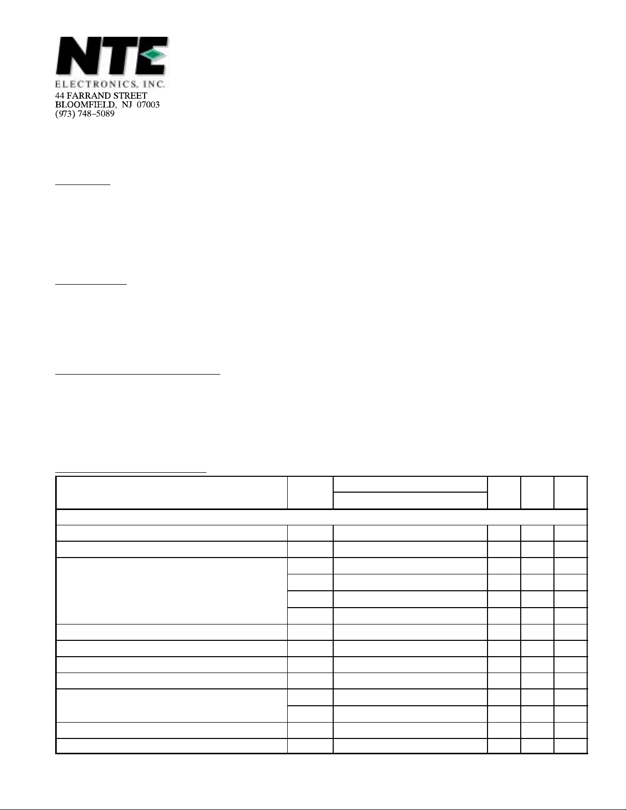
Electrical Characteristics: (TA = +25°C unless otherwise specified)
Position of Test Switches
Parameter T est Pin
Static Characteristics
Supply Current 14 1 4 2 1 5 2 3 15 30 mA
Luma Input Current 15 1 4 2 1 5 2 3 425 570 µA
Luma Output Voltage 13 1 4 2 1 5 2 2 1.8 4.5 V
9 2 2 2 2 3 1 1 5.3 7.5 V
9 2 3 2 2 3 1 1 11.6 13.0 V
9 2 1 2 2 1 1 1 14.1 15.7 V
Luma Blanking Current 9 3 1 2 2 3 1 1 – 1.0 µA
Video Output Short Circuit Current 11 1 4 1 1 5 2 2 5.0 14 mA
Clamped Video Level 12 1 4 2 1 1 1 1 2.5 3.9 V
Clamp Leakage Current 12 1 4 2 1 4 1 1 0 365 nA
Chroma Output Voltage
Gate Leakage Current 10 1 4 2 1 2 1 1 0 400 nA
Loop Filter Voltage 1 1 4 2 1 2 1 1 5.0 5.8 V
6 2 4 2 1 5 2 3 7.3 9.1 V
6 3 1 2 2 3 1 1 10.3 11.6 V
A B C D E F G
Min Max Unit
Electrical Characteristics (Cont’d): (TA = +25°C unless otherwise specified)
Position of Test Switches
Parameter T est Pin
Dynamic Characteristics
Video Output Minimum 9 1 1 1 2 (Test 1) 0.20 0.56 V
Mid 9 2 1 1 2 0.80 1.50 V
Maximum 9 3 1 1 2 (Test 2) 1.50 2.60 V
Video Gain Ratio Test 2/Test 1 (Test A) 5.0 8.5
Video Frequency Response 9 3 1 1 2 f = 3.58MHz 1.0 2.6 V
Limited Video Gain 9 3 1 2 2 0.2 0.4 V
Chroma Output Minimum 6 1 2 1 1 (Test 3) 50 150 mV
Mid 6 2 2 1 1 260 440 mV
Maximum 6 3 2 1 1 (Test 4) 400 750 mV
Chroma Gain Ratio Test 4/Test 3 (Test B) 5.0 8.5
Limited Chroma Gain 6 3 2 2 1 35 150 mV
Video/Chroma Gain Ratio Test A/Test B 0.85 1.15
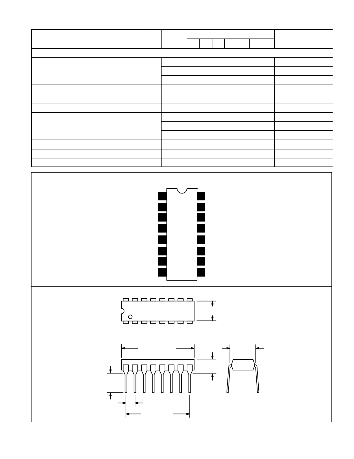
Pin Connection Diagram
A B C D E F G
Min Max Unit
rms
rms
rms
rms
rms
rms
rms
rms
rms
Voltage Reference
Automatic Brightness Limiter
ABL or GND
Chrominance Input
16 9
18
.785 (19.9)
.245
(6.22)
Min
Max
1
2
3
4
5GND
6Chrominance Output
7Vertical Pulse Input
8Video Peak
16
DC Picture Control
15
Luminance Input
V
14
CC
13
Luminance Output
12 Clamp
11 Video Output
Horizontal Pulse Input
10
Luminance Output
9
.260 (6.6) Max
.300
(7.62)
.200 (5.08)
Max
.100 (2.54)
.700 (17.7)
 Loading...