

NTE NTE815 Datasheet

NTE815
Integrated Circuit
TV Horizontal Processor
Description:
The NTE815 is an integrated circuit in an 8–Lead DIP type package containing low–level horizontal
sections including phase detector, oscillator and pre–driver–a device designed for use in all types of
television receivers.
Features:
D Internal Shunt Regulator
D Preset Hold Control Capability
D ±300Hz Typical Pull–In
D Linear Balanced Phase Detector
D Variable Output Duty Cycle for Driving Tube or Transistor
D Low Thermal Frequency Drift
D Small Static Phase Error
D Adjustable dc Loop Gain
Absolute Maximum Ratings: (TA = +25°C unless otherwise specified)
Supply Current 40mA. . . . . . . . . . . . . . . . . . . . . . . . . . . . . . . . . . . . . . . . . . . . . . . . . . . . . . . . . . . . . . . . . . .
Output Voltage, V
Output Current, I
Sync Input Voltage (Pin 3) 5V
Flyback Input Voltage (Pin 4) 5V
Power Dissipation (Package limitation), P
O
O
30mA. . . . . . . . . . . . . . . . . . . . . . . . . . . . . . . . . . . . . . . . . . . . . . . . . . . . . . . . . . . . . . . .
. . . . . . . . . . . . . . . . . . . . . . . . . . . . . . . . . . . . . . . . . . . . . . . . . . . . . . . .
. . . . . . . . . . . . . . . . . . . . . . . . . . . . . . . . . . . . . . . . . . . . . . . . . . . . .
D
625mW. . . . . . . . . . . . . . . . . . . . . . . . . . . . . . . . . . . . . . . . .
Derate above 25° 5.0mW/°C. . . . . . . . . . . . . . . . . . . . . . . . . . . . . . . . . . . . . . . . . . . . . . . . . . . . . .
Operating Ambient Temperature Range, T
Storage Temperature Range, T
stg
A
0° to +75°C. . . . . . . . . . . . . . . . . . . . . . . . . . . . . . . . . . . . .
–65° to +150°C. . . . . . . . . . . . . . . . . . . . . . . . . . . . . . . . . . . . . . . . . .
40V. . . . . . . . . . . . . . . . . . . . . . . . . . . . . . . . . . . . . . . . . . . . . . . . . . . . . . . . . . . . . . . . .
(p–p)
(p–p)
Electrical Characteristics: (TA = +25°C unless otherwise specified)
Parameter Test Conditions Min Typ Max Unit
Regulated Voltage (Pin6) 8.0 8.4 8.8 V
Supply Current (Pin6) – 20 – mA
Collector–Emitter Saturation Voltage (Output Transistor) IC = 20mA, Pin1 – 0.30 0.35 V
Voltage (Pin4) – 2.0 – V
Oscillator Pull–In Range – ±300 – Hz
Oscillator Hold–In Range – ±900 – Hz
Static Phase Error ∆f = 300Hz – 0.5 – µs
Free–Running Frequency Supply Dependence – ±3.0 – Hz/V
Phase Detector Leakage (Pin5) – – ±1.0 µA
Sync Input Voltage (Pin3) 2.0 – 5.0 V
Sawtooth Input Voltage (Pin4) 1.0 – 3.0 V
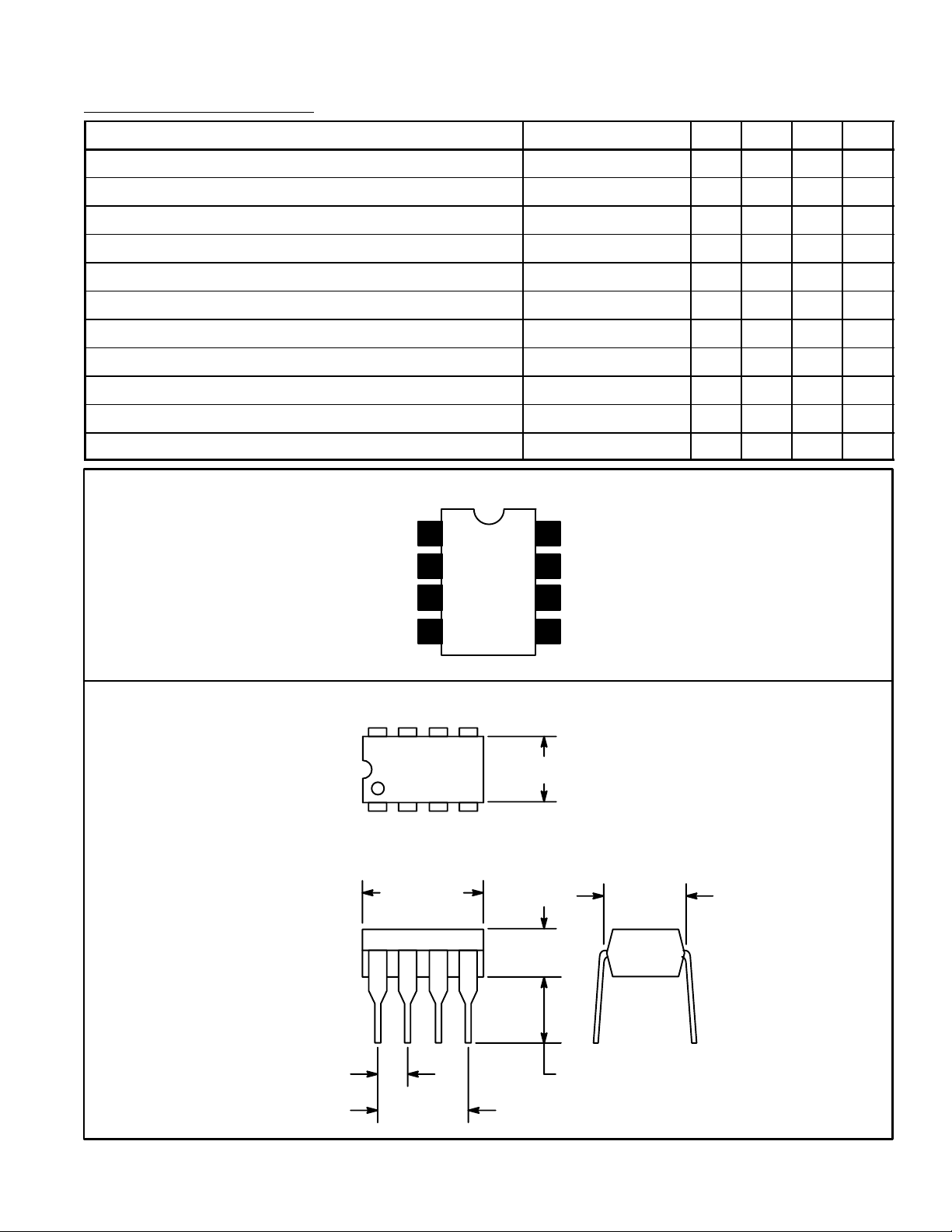
Pin Connection Diagram
Output
GND
Sync Input
(+) Horizontal Input
85
14
2
3
4
Mark Space Ratio1
8
7
OSC Timing
6
V
5
Det Output
.260 (6.6)
CC
P–P
P–P
.100 (2.54)
.390 (9.9)
Max
.300 (7.62)
.300
(7.62)
.155
(3.93)
.145 (3.68)
 Loading...