

NTE NTE799 Datasheet
NTE799
Integrated Circuit
Four Channel “SQ” Decoder
Description:
The NTE799 consists of two high input impedance preamplifiers which are fed with left total, LT, and
right total, R
signals in quadrature and two RT signals in quadrature. The four signals are matrixed to yield left front,
left back, right front, and right back signals (L
signals. The preamplifiers each feed two all–phase networks which generate two L
T
, LB, RF, RB).
F
T
Absolute Maximum Ratings
Power Supply Voltage, V
Power Dissipation (T
= +25°C), P
A
: (TA = +25°C unless otherwise specified)
CC
D
750mW. . . . . . . . . . . . . . . . . . . . . . . . . . . . . . . . . . . . . . . . . . . . . .
Derate Above +25°C 6.7mW/°C. . . . . . . . . . . . . . . . . . . . . . . . . . . . . . . . . . . . . . . . . . . . . . . . . . . .
Operating Temperature Range, T
Storage Temperature Range, T
Electrical Characteristics:
stg
(VCC = +20V, Vin = 0.5V
opr
@ 1kHz, TA = +25°C unless otherwise
(RMS)
0° to +75°C. . . . . . . . . . . . . . . . . . . . . . . . . . . . . . . . . . . . . . . . . . .
–65° to +150°C. . . . . . . . . . . . . . . . . . . . . . . . . . . . . . . . . . . . . . . . . .
specified)
Parameter Min Typ Max Unit
Supply Current Drain 11 16 21 mA
Input Impedance 1.8 3.0 – mΩ
Output Impedance – 5.0 – kΩ
Channel Balance (LF/RF) –1.0 0 +1.0 dB
Voltage Gain LF/LT or RF/R
Relative Voltage Gain LB’/LF’ or RF/R
Maximum Input Voltage for 1% THD at Output RT or L
Total Harmonic Distortion RT or L
Signal to Noise Ratio (Short–Circuit Input VO = 0.5V
Referenced to Output Voltage, V
T
T
T
) (BW = 20Hz to 20kHz)
O
(RMS)
T
with Output Noise
–1.0 0 +1.0 dB
–1.0 0 +1.0 dB
2.0 – – V
– 0.1 – %
– 80 – dB
25V. . . . . . . . . . . . . . . . . . . . . . . . . . . . . . . . . . . . . . . . . . . . . . . . . . . . . . . . . .
(RMS)
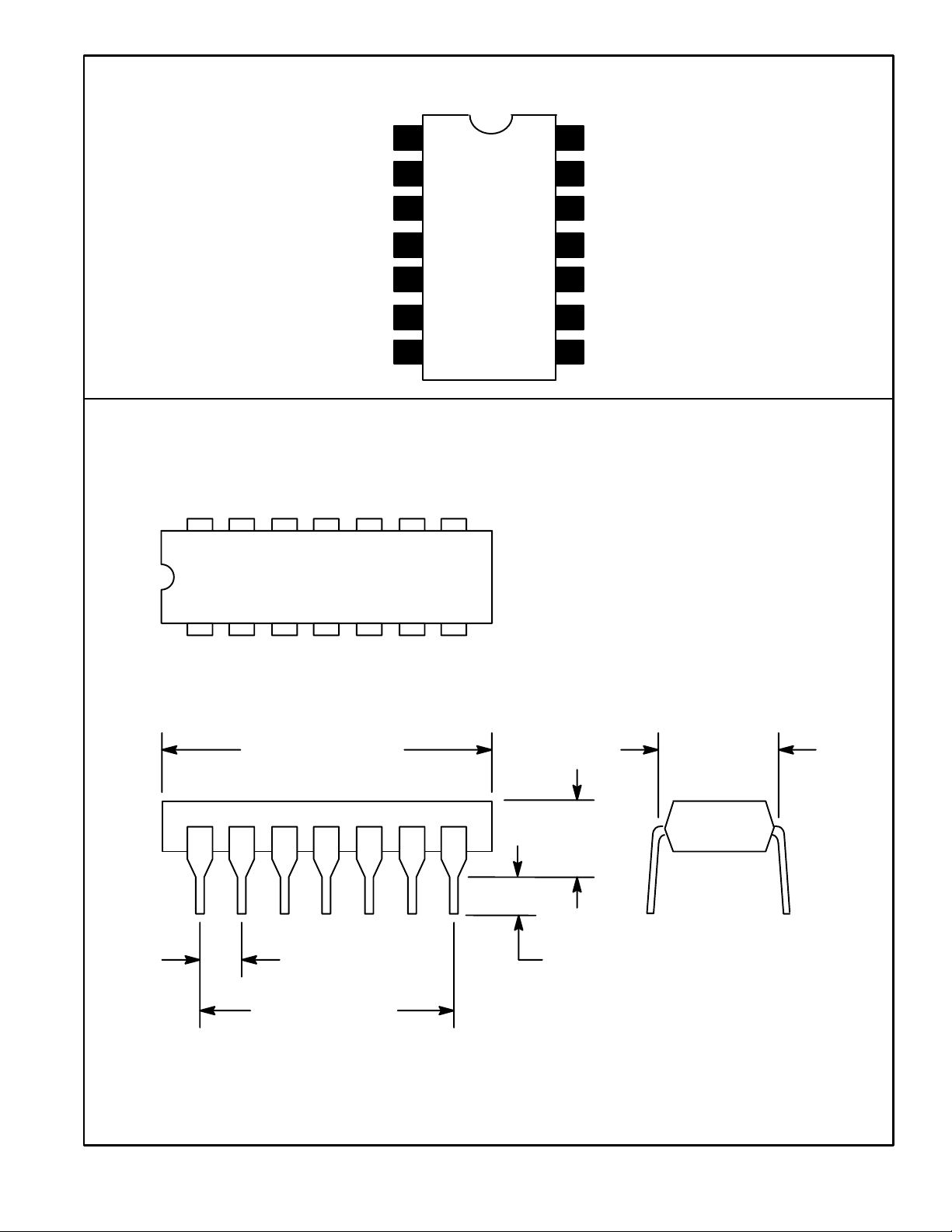
Pin Connection Diagram
Phase Shift Network
LF Output
LB Output
Phase Shift Network
1
2
3
4
5Phase Shift Network
6Lt Channel Input
7GND
14 8
RB Output
14
Phase Shift Network
13
V
12
11
CC
RF Output
10 Phase Shift Network
9 Phase Shift Network
8 Rt Channel Input
17
.785 (19.95) Max
.300 (7.62)
.200 (5.08)
Max
.100 (2.45)
.099 (2.5) Min
.600 (15.24)
 Loading...