

NTE NTE791 Datasheet
NTE791
Integrated Circuit
TV Chroma Amplifier Demodulator
Description:
Compromised of an independent 2–stage chroma amplifier, chroma demodulators, resistor matrix,
and color difference amplifiers. The NTE791 monolithic silicon integrated circuit is one of two blocks
required for a complete color television receiver chroma system.
The chroma amplifiers contain the necessary circuitry for automatic chroma control and color–killer
sensing and control. The demodulators and resistor matrix reconstruct the G–Y color chain to bypass
unwanted harmonics. The high–level emitter follower outputs are current limited for short–circuit
protection.
Features:
D DC Chroma Gain Control
D Improved Filtering for Harmonic Reduction
D Output Short–Circuit Current Limiting
D Self–Contained Bias Regulator
D Low Thermal Drift, Typically 1mV/°C
D Doubly Balanced Demodulation
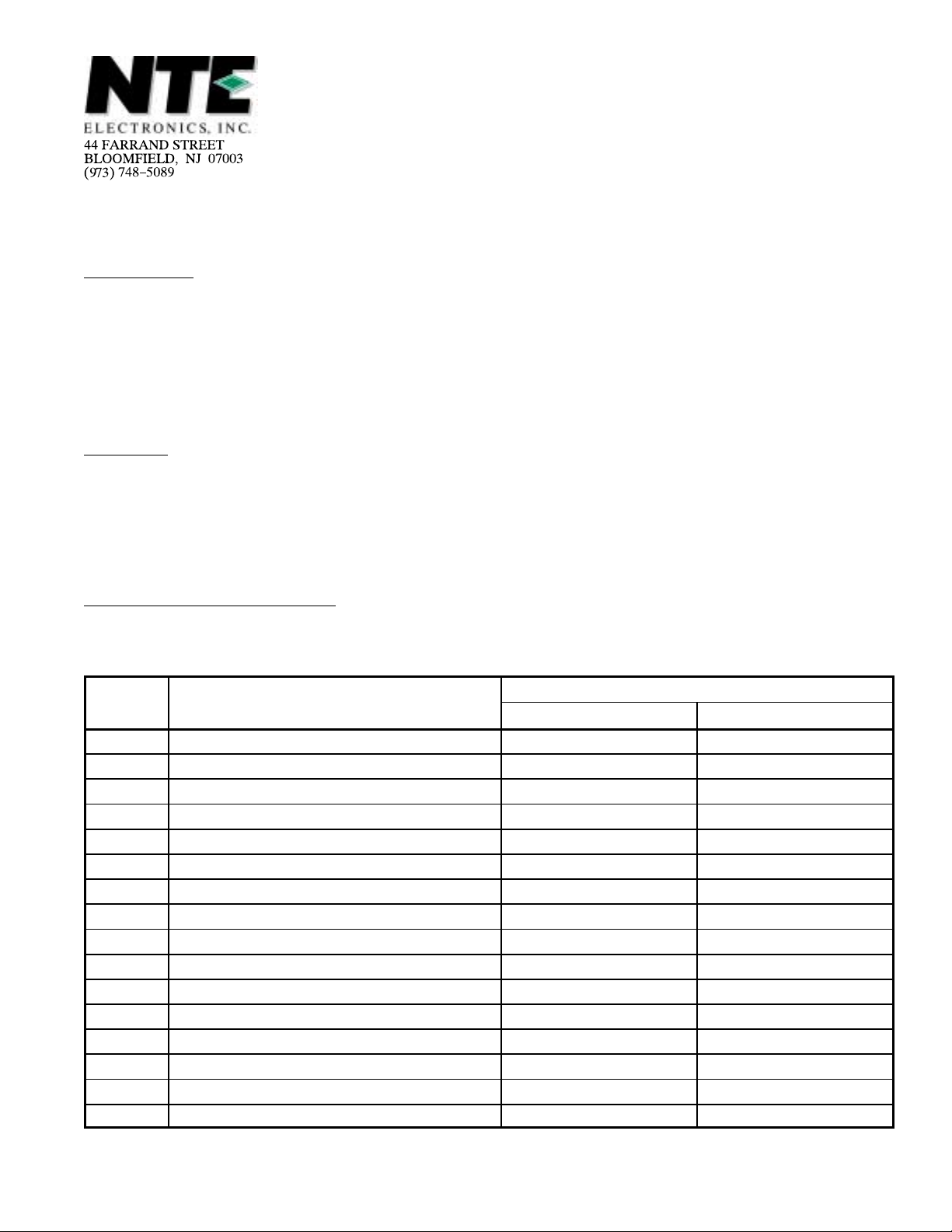
Absolute Maximum Ratings:
Operating Temperature Range, TA –40° to +85°C. . . . . . . . . . . . . . . . . . . . . . . . . . . . . . . . . . . . . . . . .
Storage Temperature Range, T
Maximum Voltage and Current Ratings (T
Pin # Voltage Range in Volts
1 0 to +16 – –
2 – 2.0 –
3 0 to V
4 – 2.0 –
5 reference 1.0 50
6 0 to V
7 0 to +15 – –
8 0 to +15 – –
9 0 to V
10 0 to V
11 0 to V
12 0 to +30 50 1.0
13 0 to +10 – –
14 0 to V
15 0 to +16 – –
16 0 to +16 – –
stg
CC
CC
CC
CC
CC
CC
= +25°C) See Table. . . . . . . . . . . . . . . . . . . . . . . . . . . . . .
A
Current in mA
Input Output
1.0 10
– –
0 Note 1
0 Note 1
0 Note 1
– –
–65° to +150°C. . . . . . . . . . . . . . . . . . . . . . . . . . . . . . . . . . . . . . . . .
Note 1. Maximum continuous current output is 20mA and is limited by package power dissipation.
Short circuit current is typically 50mA.
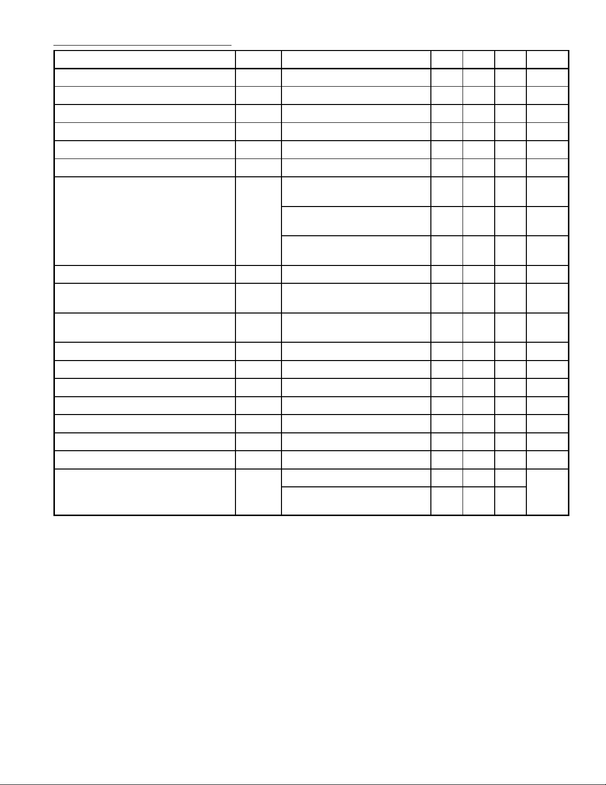
Static Electrical Characteristics: (TA = +25°C, VCC = 24V, Note 2 unless otherwise specified)
Parameter Pins Test Conditions Min Typ Max Unit
Supply Current 12 – 40 50 mA
Input D–C Voltage Chroma Demod 13 – 5.5 – V
R–Y Inj. 8 – 6.1 – V
B–Y Inj. 7 – 6.1 – V
Amplifier No. 1 2 – 1.6 – V
Amplifier No. 2 4 – 1.6 – V
Output DC Voltage Amplifier No. 1 3
V1 = V14
– 18 – V
(ACC at 1/2 Max. Gain)
V1 – V14 = 100mV
– 13 – V
(ACC Max Gain)
V14 –V1 = 100mV
– 23 – V
(ACC Min Gain)
Demodulator 9,10,11 Reference Injection = 1V
Output Differential Voltage
9,10,11 Reference Injection = 1V
pp
pp
13.3 14.3 15.3 V
– 200 600 mV
for any two outputs
Output Tracking Temperature
9,10,11 – –1.0 – mV/°C
Coefficient
Amplifier No. 1 Sensitivity 2 B–Y = 2 V
Amplifier No. 2 Sensitivity 4 B–Y = 2 V
Relative Output Voltage R–Y 10 B–Y = 2 V
Relative Output Voltage G–Y 9 B–Y = 2 V
rms
rms
rms
rms
6.3 10 15 mV
35 50 80 mV
1.4 1.52 1.68 V
300 400 500 mV
Demodulator A–C Unbalanced 9,10,11 Chroma Input = 0 – – 200 mV
90% Gain 11 V6 = 3V – 1.8 – V
10% Gain 11 V6 = 21V – 0.2 – V
Killer 11
V1 – V14 = 100mV Adj to Kill – – 500
V1 – V14 = 85mV
2.5 – –
mV
Output Must Recover
rms
rms
rms
rms
rms
rms
rms
rms
Note 2. ACC inputs biased from 11V thru 62kΩ
Note 3. B–Y Reference Injection = 1V
< 106°C
pp
 Loading...