

NTE NTE78 Datasheet
NTE78
Silicon NPN Transistor
RF Power Output
Description:
The NTE78 is a silicon NPN epitaxial planer type transistor designed for use as 3 to 4 watt RF power
amplifiers in HF band mobile radio applications.
Features:
D High Power Gain
D Emitter Ballasted Construction for High Reliability and Good Performance
Absolute Maximum Ratings:
Collector–Base Voltage, V
Collector–Emitter Voltage (R
Emitter–Base Voltage, V
Collector Current, I
Collector Dissipation (T
Collector Dissipation (T
C
A
C
EBO
= +25°C), P
= +25°C), P
Operating Junction Temperature, T
Storage Temperature Range, T
(TC = +25°C unless otherwise specified)
CBO
= 10Ω), V
BE
J
stg
CER
C
C
Thermal Resistance, Junction–to–Ambient, R
Thermal Resistance, Junction–to–Case, R
Electrical Characteristics:
Parameter Symbol Test Conditions Min Typ Max Unit
Emitter–Base Breakdown Voltage V
Collector–Base Breakdown Voltage V
Collector–Emitter Breakdown Voltage V
Collector Cutoff Current I
Emitter Cutoff Current I
DC Forward Current Gain h
Output Power P
Collector Efficiency η
(TC = +25°C unless otherwise specified)
(BR)EBOIE
(BR)CBOIC
(BR)CERIC
CBO
EBO
FE
O
C
thJC
VCB = 30V, IE = 0 – – 100 µA
VEB = 3V, IC = 0 – – 100 µA
VCE = 10V, IC = 100mA, Note 1 35 70 180
VCC = 12V, Pin = 250mW, f =
27MHz
1.5W. . . . . . . . . . . . . . . . . . . . . . . . . . . . . . . . . . . . . . . . . . . . . . .
12.5W. . . . . . . . . . . . . . . . . . . . . . . . . . . . . . . . . . . . . . . . . . . . . .
+150°C. . . . . . . . . . . . . . . . . . . . . . . . . . . . . . . . . . . . . . . . . . . . . . .
–55° to +150°C. . . . . . . . . . . . . . . . . . . . . . . . . . . . . . . . . . . . . . . . . .
thJA
83°C/W. . . . . . . . . . . . . . . . . . . . . . . . . . . . . . . . . . .
10°C/W. . . . . . . . . . . . . . . . . . . . . . . . . . . . . . . . . . . . .
= 1mA, IC = 0 5 – – V
= 1mA, IE = 0 75 – – V
= 10mA, RBE = 10Ω 75 – – V
6.0 7.5 – W
55 60 – %
75V. . . . . . . . . . . . . . . . . . . . . . . . . . . . . . . . . . . . . . . . . . . . . . . . . . . . . . .
75V. . . . . . . . . . . . . . . . . . . . . . . . . . . . . . . . . . . . . . . . . .
5V. . . . . . . . . . . . . . . . . . . . . . . . . . . . . . . . . . . . . . . . . . . . . . . . . . . . . . . . . .
4A. . . . . . . . . . . . . . . . . . . . . . . . . . . . . . . . . . . . . . . . . . . . . . . . . . . . . . . . . . . . . . . . .
Note 1. Pulse test: Pulse Width = 150µs, Duty Cycle = 5%.
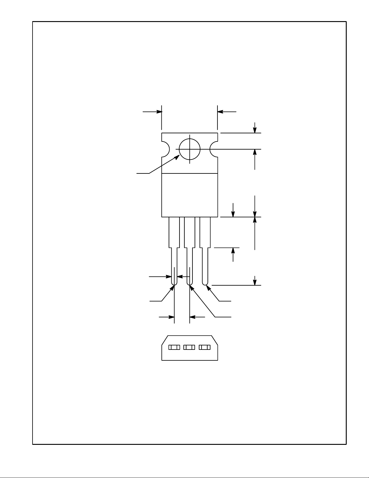
.420 (10.67)
Max
.110 (2.79)
.147 (3.75)
Dia Max
.070 (1.78) Max
Base
.100 (2.54)
.500
(12.7)
Max
.250 (6.35)
Max
.500
(12.7)
Min
Emitter
Collector/Tab
 Loading...