

NTE NTE748 Datasheet

NTE748
Integrated Circuit
TV Sound Circuit
Description:
The NTE748 is an integrated circuit in a 14–Lead DIP type pacjage designed for IF limiting, detection,
audio preamplifier and driver for the sound portion of a TV receiver.
Features:
D Excellent Limiting with 80µV(rms) Input Signal typ
D Large Output–Voltage Swing–to 3.5V(rms) typ
D High IF Voltage Gain–65dB typ
D Zener Power–Supply Regulation Built–in
D Short–Circuit Protection
D A Coincidence Discriminator that Requires Only One RLC Phase Shift Network
D Preamplifier to Drive a Single External–Transistor Class–A Audio Output Stage
Absolute Maximum Ratings
: (TA = +25°C unless otherwise specified)
Power Supply Voltage, V+ +16V. . . . . . . . . . . . . . . . . . . . . . . . . . . . . . . . . . . . . . . . . . . . . . . . . . . . . . . . .
0.7V
Input Voltage, V
Power Dissipation (Package Limitation), P
. . . . . . . . . . . . . . . . . . . . . . . . . . . . . . . . . . . . . . . . . . . . . . . . . . . . . . . . . . . . . .
in
D
625mW. . . . . . . . . . . . . . . . . . . . . . . . . . . . . . . . . . . . . . . .
Derate above +25°C 5.0mW/°C. . . . . . . . . . . . . . . . . . . . . . . . . . . . . . . . . . . . . . . . . . . . . . . . . . . .
Operating Temperature Range, T
Storage Temperature Range, T
Electrical Characteristics
: (V+ = 12V, TA = +25°C, f = 4.5MHz, Deviation = ±25kHz unless
0° to +75°C. . . . . . . . . . . . . . . . . . . . . . . . . . . . . . . . . . . . . . . . . . . .
A
–65° to +150°C. . . . . . . . . . . . . . . . . . . . . . . . . . . . . . . . . . . . . . . . . .
stg
otherwise specified)
Parameter Symbol Test Conditions Min Typ Max Unit
Input Voltage V
AM Rejection AMR
Total Harmonic Distortion THD QL = 24, 7.5kHz Deviation, Note 1 – 1.0 – %
Maximum Undistorted Audio
Output Voltage (Pin10)
V
o(max)
–3dB Limiting – 80 160 µV
L
V
Vin = 20mV
AM = 30%,
AMR = 20 log,
Note 1
Audio Gain Adjusted Externally, Q = 24, Note 1 – 3.5 – V
rms
,
: f = 4.5MHz,
OFM
Deviation = ±25kHz, Q
V
: f = 5.5MHz,
OAM
Deviation = ±50kHz, Q
= 24
L
= 30
L
– 45 – dB
– 45 – dB
(rms)
rms
rms
Electrical Characteristics (Cont’d): (V+ = 12V, TA = +25°C, f = 4.5MHz, Deviation = ±25kHz
unless otherwise specified)
Parameter Symbol Test Conditions Min Typ Max Unit
Recovered Audio (Pin2) V
Audio Preamplifier A
IF Voltage Gain A
Parallel Input Resistance R
Parallel Input Capacitance C
Nominal Zener Voltage V
Power Supply Current I
Power Dissipation P
VIF
RegIZ
Note 1. QL is loaded circuit Q.
Audio Output
f = 4.5MHz, Deviation = ±25kHz, QL = 24, Note 1 0.35 0.50 – V
A
f = 5.5MHz, Deviation = ±50kHz, QL = 30, Note 1 – 0.80 – V
Open Loop Gain – 25 – dB
VP
– 65 – dB
in
in
= 5mA – 11.6 – V
IZ = 5mA – 31 – mA
D
IZ = 5mA – 300 375 mW
D
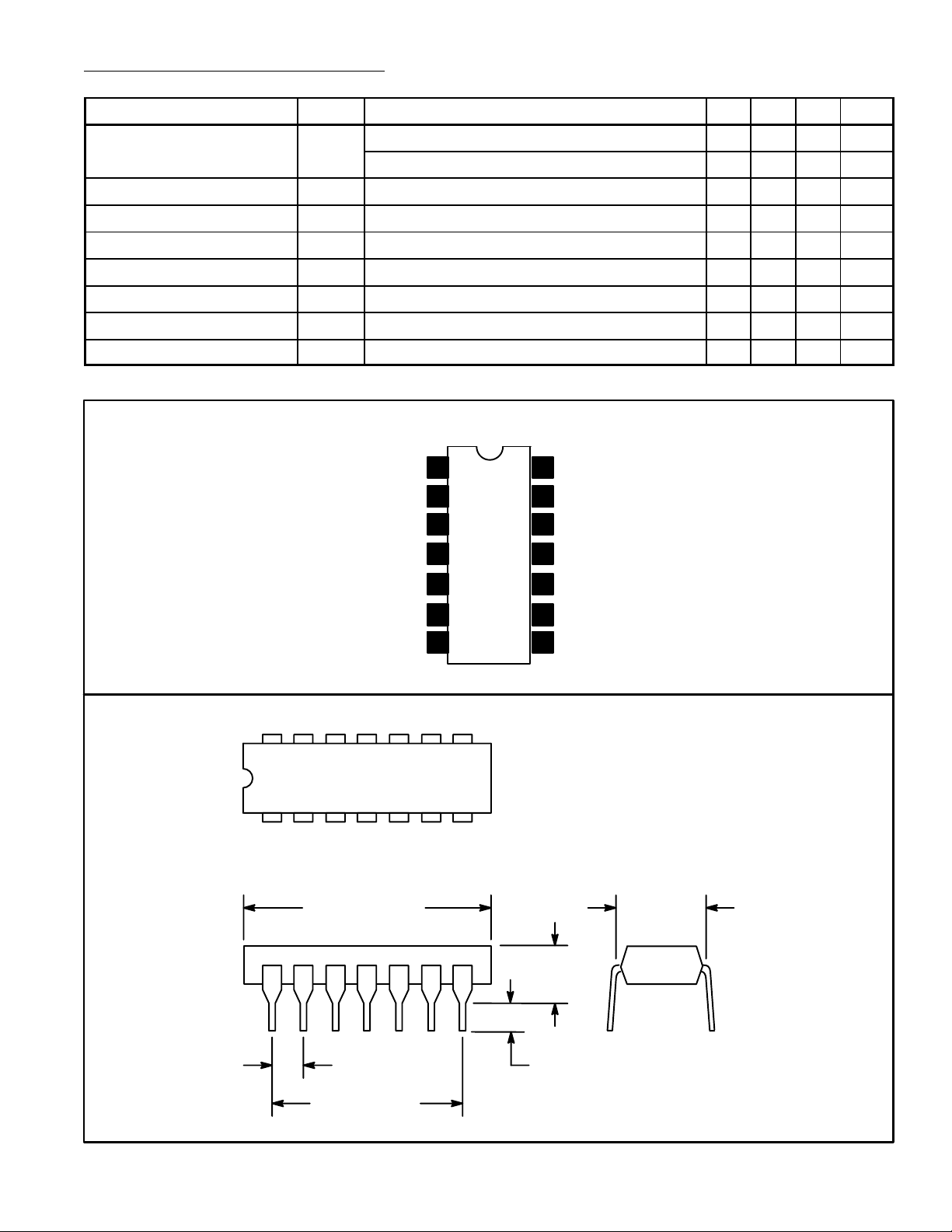
Pin Connection Diagram
Bypass
Bypass
IF Input
1
2
3
4
5Bypass
V
14
CC
13
Quadrature Network
Test Point
12
11
Quadrature Bypass
10 Preamp Output
– 9.0 – kΩ
– 6.0 – pF
rms
rms
6Bypass
7GND
9 Preamp Input
IF Output
8
14 8
17
.785 (19.95)
Max
.200 (5.08)
Max
.300
(7.62)
.100 (2.45) .099 (2.5) Min
.600 (15.24)
 Loading...