

NTE NTE746 Datasheet
NTE746
Integrated Circuit
TV Video IF Amplifier
Description:
The NTE746 is a monolithic integrated circuit in an 8–Lead DIP type package with wide–range AGC
st
for replacement of 1
rd
drive a 3
IF stage.
Features:
D Center Frequency: FO = 45MHz
D Bandwidth: BW = 6MHz
D Power Gain: 50dB Min
D AGC Range: 60dB Min
D Low Reverse–Transfer Admittance: 1µmho Typ
Applications:
D TV Video IF
D Defense Communications Satellite Programs
D Combined AM/FM Radio IF Amplifiers
D Linear Switch or Chopper for Multiplex Modulation or Demodulation
and 2nd IF stages in solid–state color and black and white TV sets. It will directly
D Y
Constant to 75MHz
21
D 12V Operation, Single–Polarity Power Supply
D Total Supply Current: 20mA Typ
D Nearly Constant Input and Output Admittance
over the Entire AGC Range
Absolute Maximum Ratings:
(TA = +25°C)
Power Supply, V+ 18V. . . . . . . . . . . . . . . . . . . . . . . . . . . . . . . . . . . . . . . . . . . . . . . . . . . . . . . . . . . . . . . . . .
Output Supply, V
AGC Supply, V
Differential Input Voltage, V
Power Dissipation, P
1
AGC
, V
8
4V < V
in
D
AGC
625mW. . . . . . . . . . . . . . . . . . . . . . . . . . . . . . . . . . . . . . . . . . . . . . . . . . . . . . . . . .
Derate Above 25°C 5mW/°C. . . . . . . . . . . . . . . . . . . . . . . . . . . . . . . . . . . . . . . . . . . . . . . . . . . . . . .
Operating Temperature Range, T
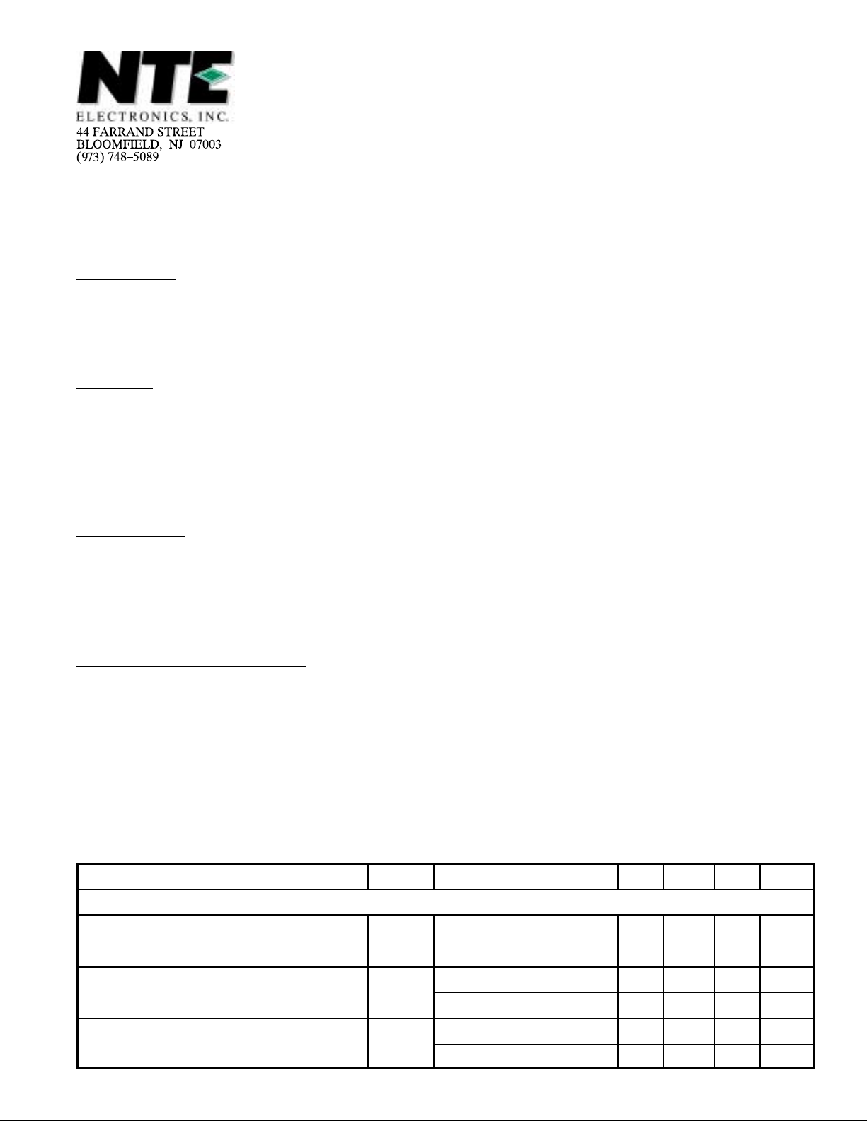
Electrical Characteristics:
Parameter Symbol Test Conditions Min Typ Max Unit
DC Characteristics
Total Supply Current I
Output Stage Current I1 + I
AGC Supply Voltage V
AGC Supply Current I
A
(V+ = 12V, TA = +25°C unless otherwise specified)
S
AGC
AGC
Pin1, Pin2, and Pin8 – 20 – mA
8
0dB Attenuation – 5.0 – V
60dB Attenuation – 6.9 – V
0db Attenuation – 0.1 – mA
60dB Attenuation – 0.2 – mA
– 6.5 – mA
0° to +75°C. . . . . . . . . . . . . . . . . . . . . . . . . . . . . . . . . . . . . . . . . . . . .
18V. . . . . . . . . . . . . . . . . . . . . . . . . . . . . . . . . . . . . . . . . . . . . . . . . . . . . . . . . . . . . . .
< V+. . . . . . . . . . . . . . . . . . . . . . . . . . . . . . . . . . . . . . . . . . . . . . . . . . . . . .
±7V. . . . . . . . . . . . . . . . . . . . . . . . . . . . . . . . . . . . . . . . . . . . . . . . . . . . . . . . .
Electrical Characteristics (Cont’d): (V+ = 12V, TA = +25°C unless otherwise specified)
Parameter Symbol Test Conditions Min Typ Max Unit
Small–Signal Characteristics (f = 45MHz)
Power Gain BW = 6MHz – 46 50 dB
Y–Parameters
Single–Ended Input Admittance
g11 – 1.0 – mmho
b11 – 2.8 – mmho
Differential Output Admittance g22 – 0.07 – mmho
b22 – 0.50 – mmho
Differential Admittance Variation w/ AGC
Input Admittance
g11 0dB to 60dB – 0.06 – mmho
b11 – 0.0 – mmho
Output Admittance g22 – 0.004 – mmho
b22 – 0.04 – mmho
Y
0dB Agc – 0.2 – mho
21
Useable AGC Range in 45MHz TV IF – > 60 – dB
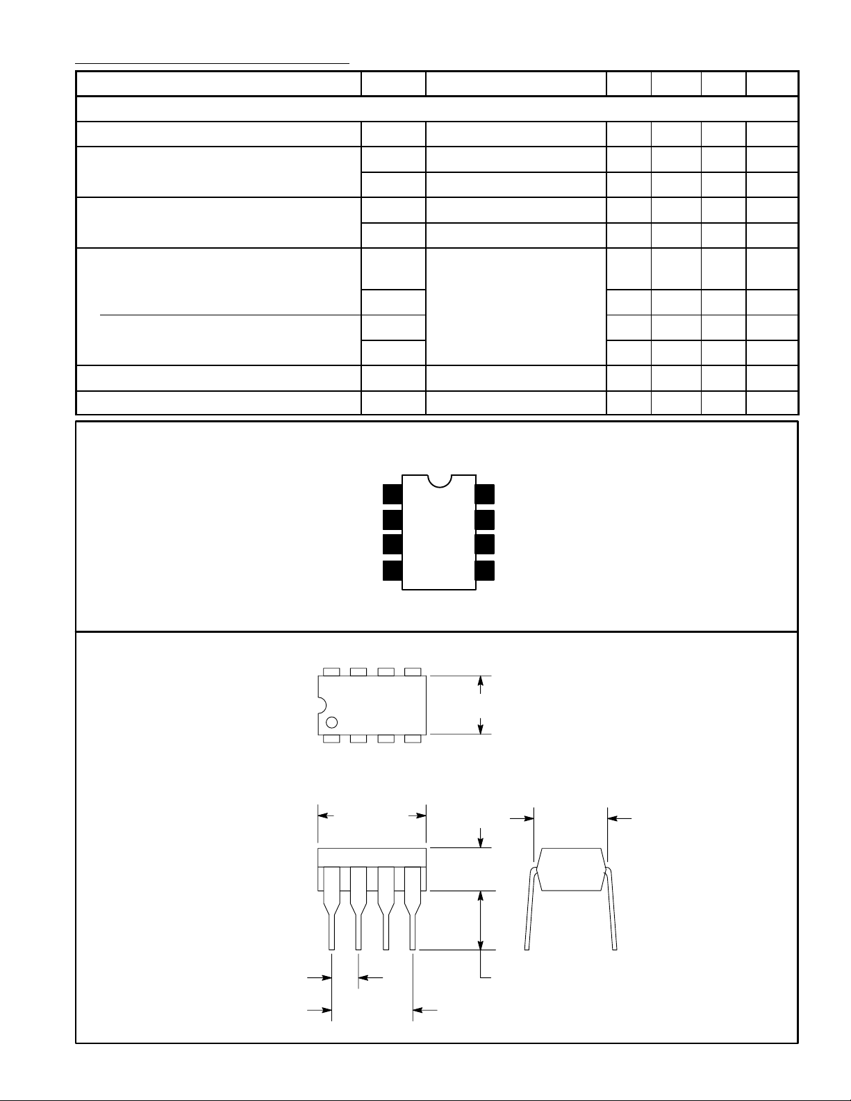
Pin Connection Diagram
IF Output
V
CC
GND
2
3
8
7
6
IF Output1
GND
(+) Input
(–) Input
85
14
4
.260 (6.6)
.390 (9.9)
Max
.155
(3.93)
5
Input
.300
(7.62)
.100 (2.54)
.145 (3.68)
.300 (7.62)
 Loading...