

NTE NTE743 Datasheet
NTE743
Integrated Circuit
Phase Lock Loop (PLL) Stereo Decoder
Description:
The NTE743 requires only a single, non critical resistive tuning adjustment. This device derives left
and right audio channels from the standard composite stereo decoder can also be used in a number
of subscription TV decoder schemes or in various proposed TV stereo systems.
Using phase–lock techniques, the subcarrier (38 KHz for FM stereo) is regenerated in phase with and
at exactly twice the frequency of the transmitted pilot signal. Switching between monaural and stereo
operation is accomplished automatically by the presence of the pilot signal.
Low–impedance emitter–follower outputs and an internal voltage regulator for increased stability
make the NTE743 suitable for both line–operated and automotive applications. It is designed to operate over a wide supply–voltage range and will function with supplies as low as 9V.
Features:
D Internal Temperature Compensation
D Single–Adjustment Tuning
D Automatic Stereo/Mono Switching
D Stereo Indicator Lamp Driver
D 70dB SCA Rejection
D Operating Voltage– 9 to 16V
D Low Harmonic Distortion
Absolute Maximum Ratings:
Supply Voltage, V
CC
Continous +16V. . . . . . . . . . . . . . . . . . . . . . . . . . . . . . . . . . . . . . . . . . . . . . . . . . . . . . . . . . . . . . . . . .
≤15s +22V. . . . . . . . . . . . . . . . . . . . . . . . . . . . . . . . . . . . . . . . . . . . . . . . . . . . . . . . . . . . . . . . . . . . . . .
Lamp Supply Voltage, V
Lamp Current, I
Output Current, I
LAMP
or I
4
Package Power Dissipation, P
LAMP
5
D
Derate Above 70°C 8.3mW/°C. . . . . . . . . . . . . . . . . . . . . . . . . . . . . . . . . . . . . . . . . . . . . . . . . . . . .
Operating Temperature Range, T
Storage Temperature Range, T
stg
+22V. . . . . . . . . . . . . . . . . . . . . . . . . . . . . . . . . . . . . . . . . . . . . . . . . . . . . . .
150mA. . . . . . . . . . . . . . . . . . . . . . . . . . . . . . . . . . . . . . . . . . . . . . . . . . . . . . . . . . . . .
10mA. . . . . . . . . . . . . . . . . . . . . . . . . . . . . . . . . . . . . . . . . . . . . . . . . . . . . . . . . . . .
670mW. . . . . . . . . . . . . . . . . . . . . . . . . . . . . . . . . . . . . . . . . . . . . . . . . .
A
–20° to +85°C. . . . . . . . . . . . . . . . . . . . . . . . . . . . . . . . . . . . . . . . . . .
–65° to +150°C. . . . . . . . . . . . . . . . . . . . . . . . . . . . . . . . . . . . . . . . . .
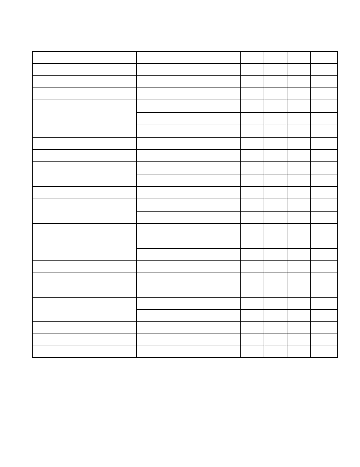
Electrical Characteristics:
(TA = +25°C, VCC = +12V, Composite Input = 300mV
= 400Hz or 1KHz, unless otherwise indicated)
f
m
(L = R, Pilot OFF), Pilot Level = 30mV
rms
rms
,
Characteristics
Test Conditions Min Typ Max Unit
Input Impedance Pin2 2 353 – kΩ
Output Impedance Pin4 or Pin5 – 50 – Ω
Audio Voltage Gain Desired Channel 0.7 1.0 1.4 V
Stereo Channel Separation
fm = 100Hz – 30 – dB
fm = 400Hz 30 40 – dB
fm = 10kHz – 30 – dB
Monaural Channel Balance Pilot Level = 0V – 0.1 1.5 dB
Total Harmonic Distortion Multiplex Level = 600mV – 0.4 1.5 %
Ultrasonic Frequency Rejection
19kHz 25 35 – dB
38kHz 25 40 – dB
SCA Rejection 67KHz, Note 1 – 70 – dB
Stereo Switch Level
Pilot Only, Lamp On – 14 25 mV
Pilot Only, Lamp Off 2.0 7.0 – mV
rms
rms
VCO Tuning Resistance Pin15, Note 2 20 23 26 kΩ
VCO Frequency Drift
–20°C < TA < +25°C – ±0.5 ±2.0 %
+25°C < TA < +70°C – ±0.5 ±2.0 %
Stereo Lamp Hysteresis Lamp Off to Lamp On 3.0 6.0 – dB
Capture Range Permissable Tuning Error – 4.0 – %
Output Voltage Shift Stereo to Mono Operation – ±30 – mV
Lamp Output Current Short Circuit, Lamp On 50 100 – mA
Lamp Off – 1.0 100 mA
Lamp Driver Terminal Voltage I
= 50mA – 1.3 2.0 V
LAMP
Supply Current Lamp Off – 20 40 mA
Power Supply Rejection 200Hz, 200mV
rms
– 40 – dB
Note 1. Measured with a stereo composite signal of 80% stereo, 10% pilot, and 10% SCA.
Note 2. Total resistance from Pin15 to GND, to set reference frequency at Pin11 to 19kHz ±10Hz
 Loading...