

NTE NTE742 Datasheet
NTE742
Integrated Circuit
TV Sound Channel, 2W
Description:
The NTE742 is designed for use as the entire sound function in television receivers or FM table radios.
The NTE742 sound channel will directly drive a 16 ohm speaker with more than 2 watts output. This
monolithic integrated circuit will operate from a single 18V to 28V power supply and can also function
(with reduced power output) with supplies as low as 12V if additional decoupling is provided.
The NTE742 is supplied in an improved 16–lead plastic dual in–line package with heat–sink contact
tabs. A copper alloy lead frame allows maximum power dissipation with standard cooling methods.
The unique lead configuration allows easy attachment of a heat sink and yet permits the use of a standard IC socket or printed wiring board layout.
Features:
D Low limiting Threshold
D Low External Parts Count
D Wide Operating Voltage Range
D 70dB Limiter Gain
D Automatic Thermal Shutdown
D Output Current Limiting
D Ripple Rejection Greater Than 20dB
Absolute Maximum Ratings:
Supply Voltage, V
Regulator Output Current, I
Input Voltage (Pin 10), V
Operating Temperature Range, T
Storage Temperature Range, T
Static Electrical Characteristics:
Parameter Symbol Test Conditions Min Typ Max Unit
Quiescent Supply Current I
Terminal Voltage V
CC
IN
REG
–40° to +85°C. . . . . . . . . . . . . . . . . . . . . . . . . . . . . . . . . . . . . . . . . .
A
S
(TA = +25°C, VCC = 24V unless otherwise specified)
V14, V
V
V
CC
V
OUT
REG
V
IN
V
16
–65° to +150°C. . . . . . . . . . . . . . . . . . . . . . . . . . . . . . . . . . . . . . . . . . .
VIN = 0 25 45 60 mA
VIN = 0 – 10 – V
2
3
15
– 2.6 – V
– 12 – V
14 15 16 V
– 1.4 – V
– 4 – V
– 8 – V
+28V. . . . . . . . . . . . . . . . . . . . . . . . . . . . . . . . . . . . . . . . . . . . . . . . . . . . . . . . . . . . . . .
10mA. . . . . . . . . . . . . . . . . . . . . . . . . . . . . . . . . . . . . . . . . . . . . . . . . . . .
+4.0V. . . . . . . . . . . . . . . . . . . . . . . . . . . . . . . . . . . . . . . . . . . . . . . . . . . . . . . . .
Dynamic Electrical Characteristics:
(TA = +25°C, VCC = 24V, fo = 4.5MHz, fm = 400Hz, ∆f = 25kHz, VIN = 10mV unless otherwise specified)
Parameter Symbol Test Conditions Min Typ Max Unit
Input Limiting Threshold V
AM Rejection AMR Note 2 30 > 50 – dB
Recovered Audio V
Total Harmonic Distortion THD Test Pin16 – < 1 3 %
Volume Control Voltage V
Playthrough V1 = 0V – 5 25 mV
Power Amp Voltage Gain A
Output Current Limiting I
Output Tracking V
Output Noise e
Power Amp Impedance Z
Note 1. Adjust V1 for V
Note 2. Adjust V
for V
1
Note 3. Reference is V
= 2V, then reduce VIN until V
OUT
= 2V.
OUT
at Pin 6 with V1 = 12V.
OUT
TH
OUT
1
e
OUT
OUT/VCC
n
in
Note 1 – 150 400 µV
500 700 900 mV
Test Pin6, P
–3dB, Note 3 6.0 7.5 10 V
–20dB, Note 3 2.0 2.8 4.0 V
–40dB, Note 3 0.75 1.2 1.8 V
V
= 1V 25 27 29 dB
OUT
RL = 0Ω – 800 – mA
VCC = 18V to 27V – 0.5 – V/V
VIN = 0V, V1 = 10V – 5 25 mV
f = 1kHz – 50 – kΩ
= 2W – 2.5 10 %
OUT
= 1.4V (–3dB).
OUT
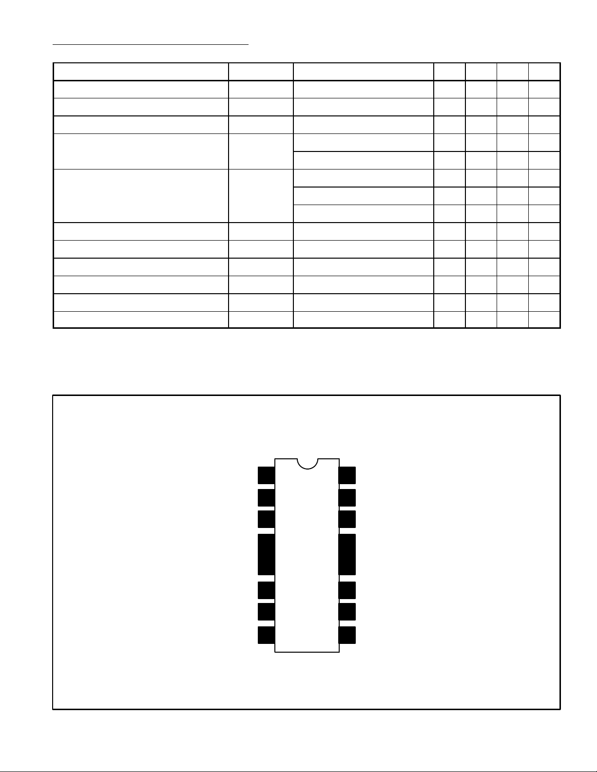
DC Volume Control
Detector Output
Amplifier Input
GND
V
CC
Pin Connection Diagran
1
2
3
F
i
n
6Audio Output
7
8Regulator Output
16
15
14
F
i
n
11 IF Decoupling
10
9
De–Emphasis
Phase Shift
Phase Shift
GND
IF Input
Low–Level GND
 Loading...