

NTE NTE722 Datasheet

NTE722
Integrated Circuit
FM Stereo Multiplex Decoder
Description:
The NTE722 is a monolithic FM Stereo Multiplex Decoder System in a 14–Lead DIP type package.
This integrated circuit demodulated a stereo multiplex signal into the right and left audio channels
while inherently suppressing SCA frequency components. Internal provision is made for driving an
external stereo mode indicator lamp. The excellent performance and wide supply range requirement
make the NTE722 suitable for all line–operated and automotive FM stereo multiplex applications.
Features:
D 45dB Channel Separation
D 55dB Storcast Rejection without SCA Filters
D High Current Stereo Indicator Lamp Driver
D Operation with 8V to 14V Supplies
Absolute Maximum Ratings:
Supply Voltage (Note 1), V+ 15V. . . . . . . . . . . . . . . . . . . . . . . . . . . . . . . . . . . . . . . . . . . . . . . . . . . . . . . . .
Voltage at Stereo Lamp Driver Terminal 22V. . . . . . . . . . . . . . . . . . . . . . . . . . . . . . . . . . . . . . . . . . . . . . .
Current into Stereo Lamp Driver Terminal (Note 2) 100mA. . . . . . . . . . . . . . . . . . . . . . . . . . . . . . . . . . .
Internal Power Dissipation, P
Operating Temperature Range, T
Storage Temperature Range, T
Lead Temperature (During Soldering, 10sec max), T
D
opr
stg
–55° to +125°C. . . . . . . . . . . . . . . . . . . . . . . . . . . . . . . . . . . . . . . . . .
L
670mW. . . . . . . . . . . . . . . . . . . . . . . . . . . . . . . . . . . . . . . . . . . . . . . . . . .
0° to +70°C. . . . . . . . . . . . . . . . . . . . . . . . . . . . . . . . . . . . . . . . . . .
+260°C. . . . . . . . . . . . . . . . . . . . . . . . . . . . . . . .
Note 1. Power supply transients up to 22V are permissible for periods of 15 seconds. However, e x -
tended operation at voltages greater than 15V should be avoided as the maximum allowable
internal power dissipation for this device may be exceeded.
Note 2. Rating applies to steady state current. Maximum permissible surge current during turn–on
of the Stereo Indicator Lamp is 500mA.
Electrical Characteristics: (TA = +25°C V+ = 12V, 200mV
standard stereo multiplex signal
RMS
applied to input, Note 3 unless otherwise specified)
Parameter Test Conditions Min Typ Max Unit
Supply Current – 12 18 mA
Input Resistance 12 20 – kΩ
Stereo Separation f = 100Hz – 40 – dB
f = 1kHz 30 45 – dB
f = 10kHz 20 40 – dB
Channel Balance (Monaural Input) – 0.2 – dB
Total Harmonic Distortion – 0.5 1.0 %
Voltage Gain – 1.0 – V/V
67kHz Storecast Rejection Note 4 – 55 – dB
19kHz Pilot Level Required at Input Stereo Indicator Lamp ON – 12 22 mV
Stereo Indicator Lamp OFF 4.0 8.0 – mV
High Frequency Audio Components
19kHz – 30 – dB
RMS
RMS
in Left and Right Outputs
(dB Below 1kHz Output)
Note 3. “Standard Stereo Multiplex Signal” here refers to a 200mV
38kHz – 25 – dB
RMS
(0.56V
) composite stereo
P–P
signal including 10% pilot with L = 1 and R = 1 as described in the FCC Rules of FM Broadcasting.
Note 4. Measured with a stereo composite signal consisting of 80% stereo, 10% pilot and 10% SCA
as defined in the FCC Rules on FM Broadcasting.
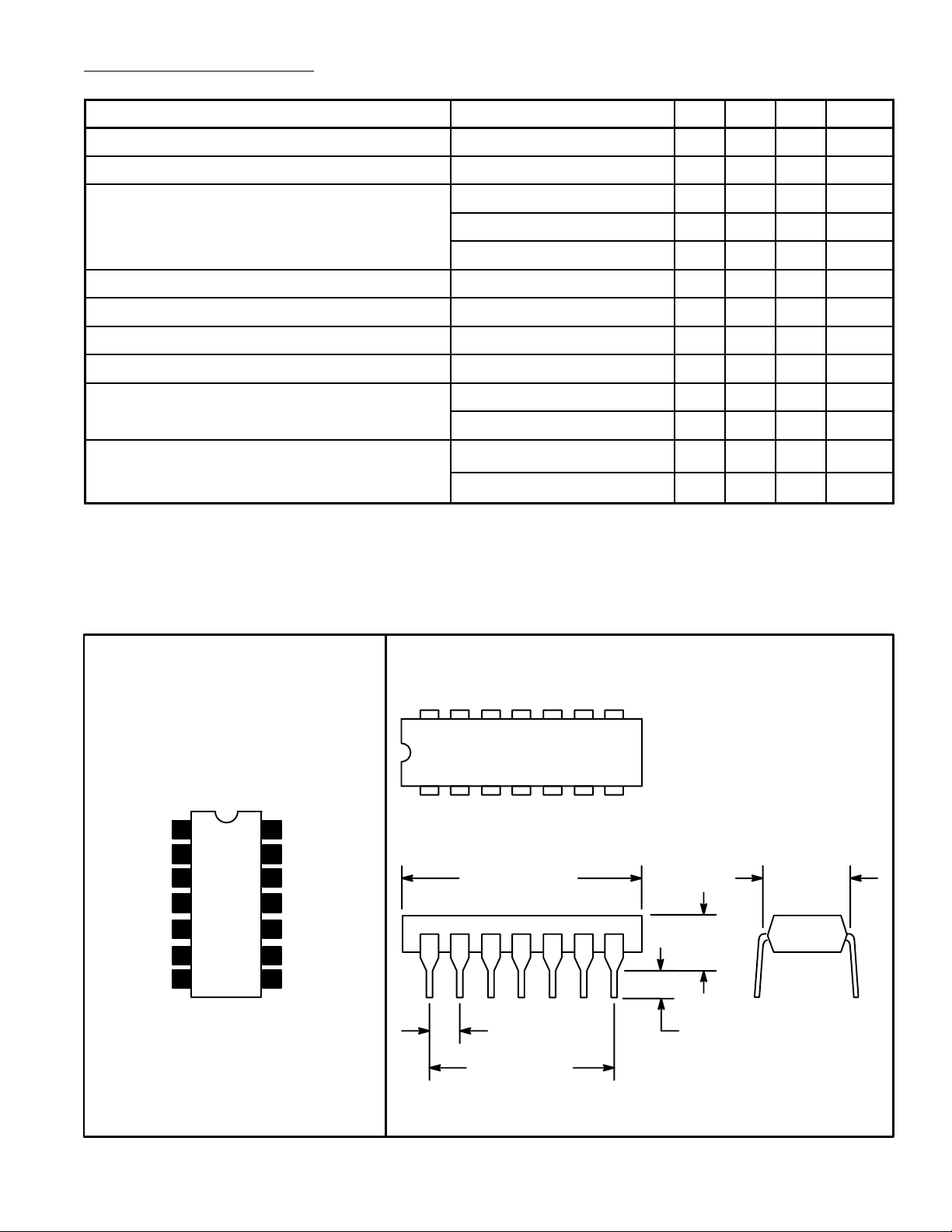
14 8
Pin Connection Diagram
17
19kHz Filter
19kHz Filter
MPX Input
N.C.
1
2
3
4
5N.C.
6Stereo Lamp
7GND
Decoupling
14
13
38kHz Filter
12
Right Output
11
Left Output
10 38kHz Filter Bias
9
V+
8 N.C.
.785 (19.95)
Max
.300 (7.62)
.200 (5.08)
Max
.100 (2.45) .099 (2.5) Min
.600 (15.24)
 Loading...