

NTE NTE7159 Datasheet

NTE7159
Integrated Circuit
Switch Mode Power Supply Controller
Description:
The NTE7159 is a monolithic integrated circuit in a 16–Lead DIP type package designed for use as
the primary part of an off–line switching mode power supply. All functions required for SMPS control
under normal operating, transient or abnormal conditions are provided.
The capability of working according to the “master–slave” concept, or according to the “primary regulation”
mode makes the NTE7159 very flexible and easy to use. This is particularly true for TV receivers where
the IC provides an attractive and low cost solution (no need of stand–by auxiliary power supply).
Features:
D Positive and Negative Current Up To 1.2A and –2A
D Low Start–Up Current
D Direct Drive of the Power Transistor
D Two Levels Transistor Current Limitation
D Double Pulse Suppression
D Soft–Starting
D Under and Overvoltage Lock–Out
D Automatic Stand–By Mode Recognition
D Large Power Range Capability in Stand–By (Burst Mode)
D Internal PWM Signal Generator
Absolute Maximum Ratings:
Power Supply (V16–V4, V5, V12, V13), V
Output Stage Power Supply (V
Output Current, I
OUT
15–V4
CC
, V5, V12, V13), V+ 20V. . . . . . . . . . . . . . . . . . . . . . . . . . . . . . . . . .
Positive (Source Current) 1.5A. . . . . . . . . . . . . . . . . . . . . . . . . . . . . . . . . . . . . . . . . . . . . . . . . . . . .
Negative (Sink Current) 2.5A. . . . . . . . . . . . . . . . . . . . . . . . . . . . . . . . . . . . . . . . . . . . . . . . . . . . . .
Operating Junction Temperature, T
StorageTemperature Range, T
Thermal Resistance, Junction–to–Case (Note 1), R
J
stg
thJC
Thermal Resistance, Junction–to–Ambient (Note 1), R
2
Note 1. Soldered on a 35µm, 40cm
board copper area.
thJA
20V. . . . . . . . . . . . . . . . . . . . . . . . . . . . . . . . . . . . . . . . . . . . .
+150°C. . . . . . . . . . . . . . . . . . . . . . . . . . . . . . . . . . . . . . . . . . . . . . .
–40° to +150°C. . . . . . . . . . . . . . . . . . . . . . . . . . . . . . . . . . . . . . . . . . .
11°C/W. . . . . . . . . . . . . . . . . . . . . . . . . . . . . .
45°C/W. . . . . . . . . . . . . . . . . . . . . . . . . . .
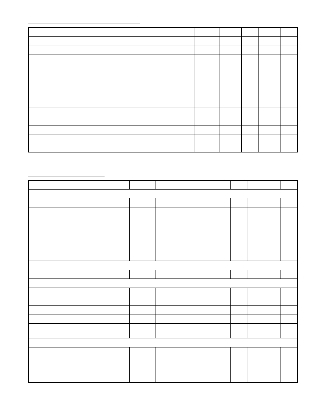
Recommended Operating Conditions:
Parameter Symbol Min Typ Max Unit
Power Supply V
Positive Output Current (Source Current) I
Negative Output Current (Sink Current) I
Average Positive Output Current I
Average Negative Output Current I
OUT
OUT
OUT
OUT
Operating Frequency F
Input Pulses Amplitude (Pin2) V
Oscillator Resistor Range R
Oscillator Capacitor Range C
CC
oper
OSC
OSC
VCCstop 12 VCCmax V
+ – – 1.2 A
– – – 2.0 A
+ – – 0.6 A
– – – 0.6 A
10 – 100 kHz
IN
1.5 2.5 4.5 V
20 – 150 kΩ
0.47 – 4.7 nF
Soft–Starting Capacitor Range C1 0.047 1.0 – µF
Overload Integration Capacitor C2 0.047 1.0 – µF
Ratio C2/C1 (C2 must be ≥ C1) C2/C1 1 – –
Operating Ambient Temperature T
A
–20 – +70 °C
Electrical Characteristics: (TA = +25°C, VCC = 12V unless otherwise specified)
Parameter Symbol Test Conditions Min Typ Max Unit
Power Supply
Starting Voltage V
Stopping Voltage V
Hysteresis Hyst V
Starting Current I
Supply Current I
Overvoltage Threshold on V
CC
Supply Current After Overvoltage Detection I
CC(start)VCC
CC(stop)VCC
CCVCC(start)
CC(start)VCC
CC
V
CC(max)
CC(over)VCC
Oscillator/PWM Section
Accuracy ∆F/F R
Error Amplifier Section
Open Loop Gain A
Unity Gain Frequency F
Short Circuit Output Current I
E Input Bias Current I
Internal Voltgage Reference V
VO
ug
SC
BE
REF
Input Section
increasing 9.3 10.3 11.3 V
decreasing 6.4 7.4 8.4 V
– V
CC(stop)
2.4 2.9 – V
= 9V – 0.7 1.4 mA
VCC = 12V – 7.5 15.0 mA
15.0 15.7 – V
= 17V 26 35 42 mA
= 68kΩ, C
OSC
= 1nF – 10 – %
OSC
– 75 – dB
– 550 – kHz
Pin7 Connected to GND – 2 – mA
Pin6 – 0.08 – µA
Connected to Error Amplifier
2.34 2.49 2.64 V
Input and Not Directly Accessible
IN Input Threshold V
IS Input Threshold V
IN Input Bias Current I
IS Input Bias Current I
BIN
BIS
Pin2 0.60 0.85 1.20 V
IN
Pin1 – 0.15 – V
IS
– 0.3 – µA
– 0.4 – µA
 Loading...