

NTE NTE7146 Datasheet
NTE7146
Integrated Circuit
Dual (12W + 12W) Stereo Amplifier w/Muting
Description:
The NTE7146 is a class AB dual audio power amplifier assembled in an 11–Lead Staggered SIP type
package specifically designed for high quality sound applications such as HI–FI music centers and
stereo TV sets.
Features:
D Wide Supply Voltage Range
D High Output Power: 12W + 12W @ VS = 28V, RL = 8Ω, THD = 10%
D Mute facility (Pop Free) with Low Consumption
D AC Short Circuit Protection
D Thermal Overload Protection
Absolute Maximum Ratings:
Supply Voltage, V
Output Peak Current, I
S
O
Repetitive (f > 20Hz) 2.5A. . . . . . . . . . . . . . . . . . . . . . . . . . . . . . . . . . . . . . . . . . . . . . . . . . . . . . . . .
Non–Repetitive (t = 100µs) 3.5A. . . . . . . . . . . . . . . . . . . . . . . . . . . . . . . . . . . . . . . . . . . . . . . . . . .
Total Power Dissipation (TC = +70°C), P
Operating Temperature Range, T
Storage Temperature Range, T
opr
stg
tot
Maximum Thermal Resistance, Junction–to–Case, R
0° to +70°C. . . . . . . . . . . . . . . . . . . . . . . . . . . . . . . . . . . . . . . . . . .
–40° to +150°C. . . . . . . . . . . . . . . . . . . . . . . . . . . . . . . . . . . . . . . . . .
thJC
35V. . . . . . . . . . . . . . . . . . . . . . . . . . . . . . . . . . . . . . . . . . . . . . . . . . . . . . . . . . . . . . . . .
25W. . . . . . . . . . . . . . . . . . . . . . . . . . . . . . . . . . . . . . . . . . . .
3°C/W. . . . . . . . . . . . . . . . . . . . . . . . . . . . . .
Electrical Characteristics: (TA = +25°C, VS = 28V, RL = 8Ω, GV = 30dB, f = 1kHz unless
otherwise specified)
Parameter Symbol Test Conditions Min Typ Max Unit
Supply Voltage V
Quiescent Output Voltage V
Total Quiescent Current I
Output Power (RMS) P
Total Harmonic Distortion THD PO = 1W, f = 1kHz – 0.02 0.2 %
S
O
q
THD = 10%, TA = +85°C 10 12 – W
O
THD = 1% – 9.5 – W
PO = 0.1W to 8W, f = 100Hz to 10kHz – – 0.5 %
10 – 32 V
– 13.5 – V
– 70 95 mA
Electrical Characteristics (Cont’d): (TA = +25°C, VS = 28V, RL = 8Ω, GV = 30dB, f = 1kHz
unless otherwise specified)
Parameter Symbol Test Conditions Min Typ Max Unit
Crosstalk CT RS = 10kΩ, f = 1kHz – 70 – dB
RS = 10kΩ, f = 10kHz – 60 – dB
Input Resistance R
Low Frequency Roll–Off (–3dB) f
High Frequency Roll–Off (–3dB) f
Total Input Noise Voltage e
I
L
H
A Curve; RS = 10kΩ – 1.5 – mV
N
100 200 – kΩ
– 40 – Hz
– 80 – kHz
f = 22Hz to 22lHz, RS = 10kΩ – 3 10 µV
Supply Voltage Rejection (Ea Channel) SVR RS = 10kΩ, f = 100Hz, Vr = 0.5V 45 60 – dB
Thermal Shutdown Junction Temperature T
J
– 145 – °C
Mute Function
Mute Threshold VT
Play Threshold VT
Mute Attenuation ATT
Quiescent Current @ Mute I
qMUTE
MUTE
PLAY
AM
1.0 1.6 – V
– 4.5 – V
70 100 – dB
– 7 10 mA
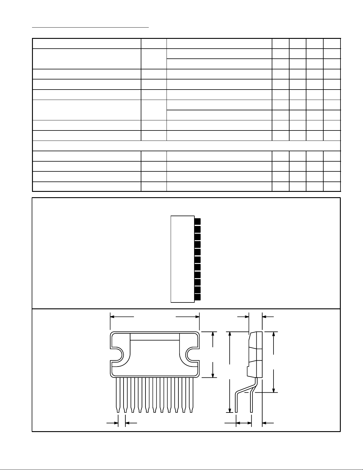
Pin Connection Diagran
(Front View)
N.C.
11
Output 1
10
(+) V
9
8
7
6
5
4
3
2
1
S
Output 2
N.C.
GND
Non–Invert Input 2
Invert Input 2
SVR/Muting
Invert Input 1
Non–Invert Input 1
.790 (20.0)
.122 (3.1)
Max
.430
(11.0)
111
.700
(17.9)
.066 (1.7) .100 (2.54) .100 (2.54)
.570
(14.4)
 Loading...