

NTE NTE7132 Datasheet
NTE7132
Integrated Circuit
Horizontal and Vertical Deflection Controller
for VGA/XGA and Multi–Frequency Monitors
Description:
The NTE7132 is an integrated circuit in a 20–Lead DIP type package. This device is designed to provide an economical solution in VGA/XGA and multifrequency monitors by incorporating complete
horizontal and vertical small signal processing. VGA–dependent mode detection and setting are performed on–chip.
Features:
D VGA Operation Fully Implemented Including Alignment–Free Vertical and E/W Amplitude
Pre–Settings
D 4th VGA Mode Easy Applicable (XGA, Super VGA)
D Mulit–Frequency Operation Externally Selectable
D All Adjustments DC–Controllable
D Alignment–Free Oscillators
D Sync Separators for Video or Horizontal and Vertical TTL Sync Levels Regardless or Polarity
D Horizontal Oscillator with P
for Sync and P
LL1
D Constant Vertical and E/W Amplitude in Multi–Frequency Operation
D Internal Supply Voltage Stabilization with Excellent Ripple Rejection to Ensure Stable Geometrical
Adjustments
for Flyback
LL2
Absolute Maximum Ratings:
Supply Voltage (Pin1), V
Voltage (Pin3, Pin7), V
Voltage (Pin8), V
8
Voltage (Pin5, Pin6, Pin9, Pin10, Pin13, Pin14, Pin18), V
Current (Pin2), I
Current (Pin3), I
Current (Pin7), I
Current (Pin8), I
2
3
7
8
Electrostatic Handling for All Pins (Note 1), V
Operating Junction Temperature, T
Operating Ambient Temperatrure Range, T
Storage Temperature Range, T
Thermal Resistance, Junction–to–Ambient (In Free Air), R
3
P
, V
7
n
esd
J
A
stg
thJA
Note 1. Equivalent to discharging a 200pF capacitor through a 0Ω series resistor.
–0.5 to +16V. . . . . . . . . . . . . . . . . . . . . . . . . . . . . . . . . . . . . . . . . . . . . . . . . . .
–0.5 to +16V. . . . . . . . . . . . . . . . . . . . . . . . . . . . . . . . . . . . . . . . . . . . . . . . . .
–0.5 to +7V. . . . . . . . . . . . . . . . . . . . . . . . . . . . . . . . . . . . . . . . . . . . . . . . . . . . . . . . . . .
–0.5 to +6.5V. . . . . . . . . . . . . . . . . . . . . .
±10mA. . . . . . . . . . . . . . . . . . . . . . . . . . . . . . . . . . . . . . . . . . . . . . . . . . . . . . . . . . . . . . . .
100mA. . . . . . . . . . . . . . . . . . . . . . . . . . . . . . . . . . . . . . . . . . . . . . . . . . . . . . . . . . . . . . . .
20mA. . . . . . . . . . . . . . . . . . . . . . . . . . . . . . . . . . . . . . . . . . . . . . . . . . . . . . . . . . . . . . . . .
–10mA. . . . . . . . . . . . . . . . . . . . . . . . . . . . . . . . . . . . . . . . . . . . . . . . . . . . . . . . . . . . . . . .
±300V. . . . . . . . . . . . . . . . . . . . . . . . . . . . . . . . . . . . . .
+150°C. . . . . . . . . . . . . . . . . . . . . . . . . . . . . . . . . . . . . . . . . . . . . . .
0° to +70°C. . . . . . . . . . . . . . . . . . . . . . . . . . . . . . . . . . . .
–55° to +150°C. . . . . . . . . . . . . . . . . . . . . . . . . . . . . . . . . . . . . . . . . .
65K/W. . . . . . . . . . . . . . . . . . . . . . . .
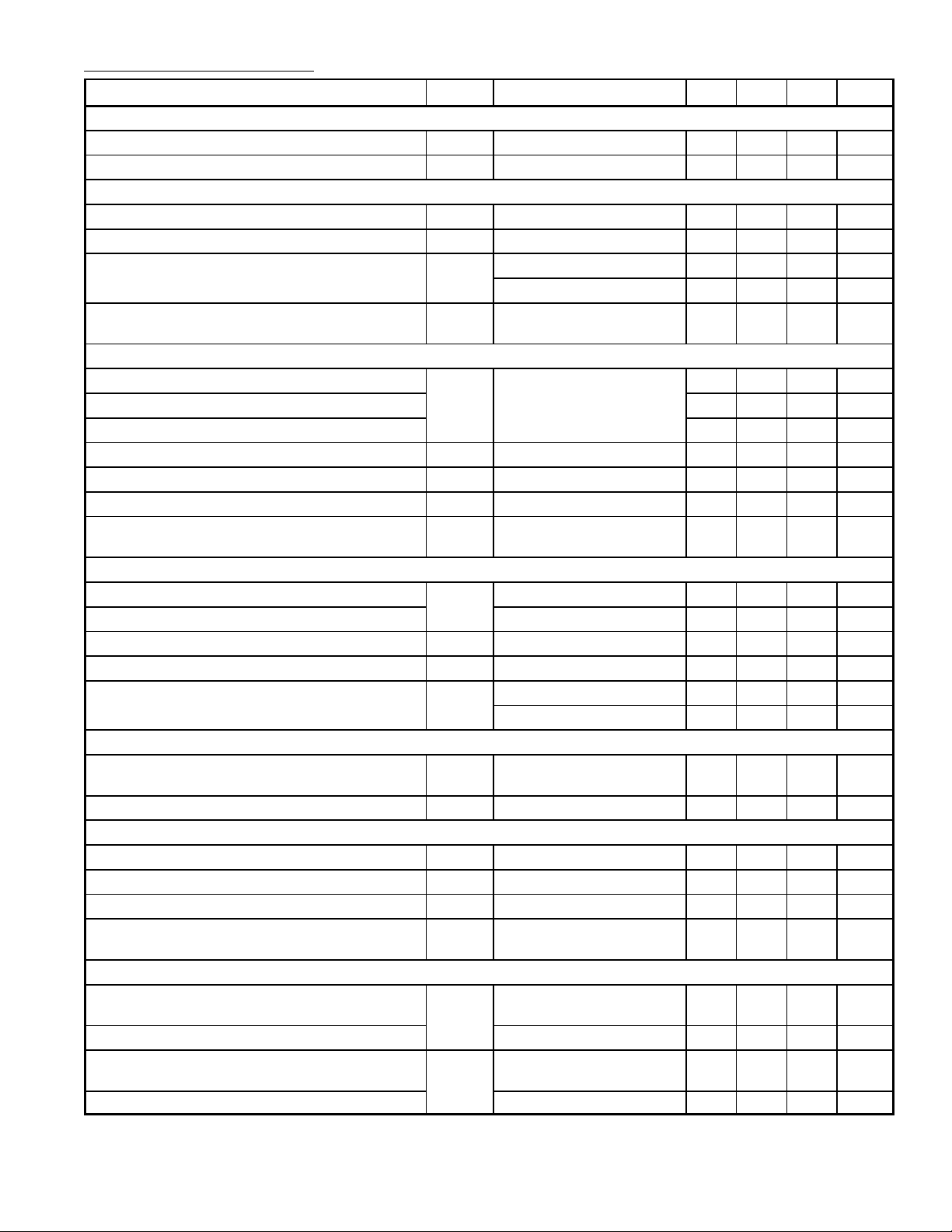
Electrical Characteristics: (VP = 12V, TA = +25°C unless otherwise specified)
Parameter Symbol Test Conditions Min Typ Max Unit
Supply
Supply Voltage (Pin1) V
Supply Current I
P
P
Internal Reference Voltage
Internal Reference Voltage V
ref
Temperature Coefficient TC TA = +20° to +100°C – – ±90 10–6/K
Power Supply Ripple Rejection PSRR f = 1kHz Sine Wave 60 75 – dB
f = 1MHz Sine Wave 25 35 – dB
Supply Voltage (Pin1) to Ensure All Internal
V
P
Reference Voltages
Composite Sync Input (AC–Coupled, V10 = 5V)
Sync Amplitude of Video Input Signal (Pin9) V
i sync
Sync on Green, RS = 50Ω – 300 – mV
Top Sync Clamping Level 1.1 1.32 1.5 V
Slicing Level Above Top Sync Level 90 120 150 mV
Allowed Source Resistance for 7% Duty Cycle R
Differential Input Resistance r
Charging Current of Coupling Capacitor I
Vertical Sync Integration Time to Generate
t
V
S
9
9
int
> 200mV – – 1.5 kΩ
i sync
During Sync – 80 – Ω
V9 > 1.5V 1.7 2.6 3.4 µA
Sync Pulse
Horizontal Sync Input (DC–Coupled, TTL–Compatible)
Sync Input Signal (Peak Value, Pin9) V
u sync
Slicing Level 1.2 1.4 1.6 V
Minimum Pulse Width t
Rise Time and Fall Time tr, t
Input Current I
p
f
V9 = 0.8V – – –200 µA
9
V9 5.5V – – 10 µA
Automatic Horizontal Polarity Switch (H–Sync on Pin9)
Horizontal Sync Pulse Width Related to t
H
t
p H/tH
(Duty Cycle for Automatic Polarity Correction)
Delay Time for Changing Sync Polarity t
p
Vertical Sync Input (DC–Coupled, TTL–Compatible,,V–Sync on Pin10)
Sync Input Signal (Peak Value, Pin10) V
i sync
Slicing Level 1.2 1.4 1.6 V
Input Current I
Maximum Vertical Sync Pulse Width for
t
p V
0 < V10 < 5.5V – – ±10 µA
10
Automatic Vertical Polarity Switch
Horizontal Mode Detector Output (VGA Mode)
Output Saturation Voltage LOW
V
I7 = 6mA – 0.275 0.33 V
7
(For Modes 1, 2, and 3)
Output Voltage HIGH Mode 4 – – V
Load Current to Force VGA Mode–Dependent
I
Modes 1, 2, and 3 2 – 6 mA
7
Vertical and Parabola Amplitudes
Output Current Mode 4 – 0 – mA
9.2 12.0 16.0 V
– 40 – mA
6.0 6.25 6.5 V
9.2 – 16.0 V
7 10 13 µs
1.7 – – V
700 – – ns
10 – 500 ns
– – 30 %
0.3 – 1.8 ms
1.7 – – V
– – 300 µs
P
V
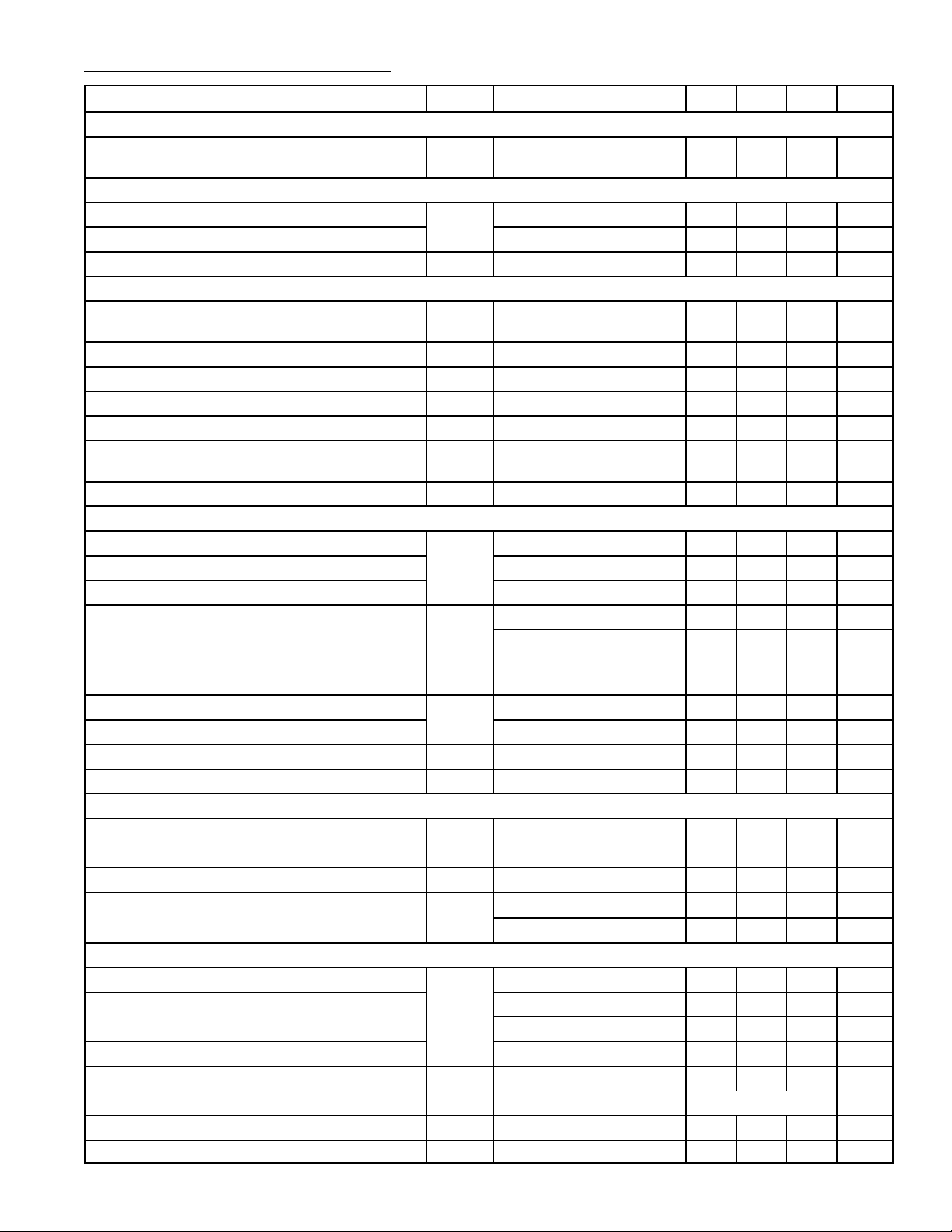
Electrical Characteristics (Cont’d): (VP = 12V, TA = +25°C unless otherwise specified)
Parameter Symbol Test Conditions Min Typ Max Unit
VGA/Multi–Frequency Mode Switch
Input Voltage LOW to Force Multi–Frequency
Mode
Horizontal Comparator P
LL1
Upper Control Voltage Limitation V
Lower Control Voltage Limitation
Control Current I
Horizontal Oscillator
Center Frequency f
Deviation of Center Frequency ∆f
Temperature Coefficient TC – – ±150 10–6/K
Relative Holding/Catching Range ϕH/t
External Oscillator Resistor R
Voltage at Reference Current Input (Pin18) V
Control Voltage ∆V
Horizontal P
LL2
Upper Clamping Level of Flyback Input V
Lower Clamping Level of Flyback Input I2 = –1mA – –0.75 – V
H–Flyback Slicing Level – 3.0 – V
Input Current I
Delay Between Middle of Sync and Middle of
H–Flyback Related to t
H
Upper Control Voltage Limitation V
Lower Control Voltage Limitation – 1.6 – V
Control Current I
P
Control range Related to t
LL2
H
Horizontal Output (Open–Collector)
Output Voltage LOW V
tH Duty Cycle tp/t
Threshold to Activate Too Low Supply Voltage
Protection
Horizontal Clamping/Blanking Generator Output
Output Voltage LOW V
Blanking Output Voltage Internal V Blanking 1.8 2.1 2.4 V
Clamping Output Voltage H–Sync on Pin9 3.5 3.9 4.3 V
Internal Sink Current for All Output Levels I
Clamping Pulse Start t
Clamping Pulse Width t
Steepness of Rise and Fall Times S – 40 – ns/V
V
OSC
OSC
td/t
∆t/t
V
7
17
0 – 50 mV
– 5.0 – V
– 1.2 – V
17
R18 = 12kΩ (Pin18),
= 2.2nF (Pin19)
C
19
– ±300 – µA
– 31.45 – kHz
– – ±3.0 %
H
18
P
18
18
2
2
and P
LL1
V
m= 6.25V
ref
I2 = 6mA – 5.5 – V
H–Scan; V8 < 0.9V –0.5 – – mA
Locked,
LL2
±6.0 ±6.5 ±7.3 %
9 – 18 kΩ
– 3.125 – V
– ±205 – mV
H–Flyback; V8 > 1.8V – – –0.2 mA
H
20
20
H
I3 = 20mA – – 0.3 V
3
– 3.2 – %
– 4.6 – V
– ±200 – µA
30 – – %
I3 = 60mA – – 0.8 V
H
Horizontal Output OFF – 5.3 – V
P
42 45 48 %
Horizontal Output ON – 5.6 – V
H and V Scanning – – 0.9 V
8
External H Blanking 1.8 2.1 2.4 V
H and V Scanning 2.3 2.9 3.5 mA
8
8
clp
With End of H–Sync
0.8 1.0 1.2 µs
 Loading...