

NTE NTE7128 Datasheet
NTE7128
Integrated Circuit
Positive Voltage Regulator
with ON/OFF Feature, 12V, 1A
Description:
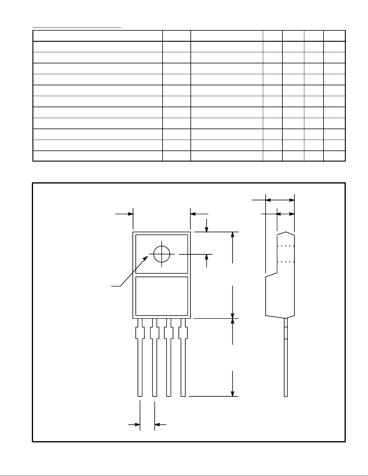
The NTE7128 is a 1A low power–loss voltage regulator in a 4–Lead TO220 type package designed
for use in constant voltage power applications in electronic equipment such as VCRs and musical
instruments.
Features:
D Low Power Loss
D Includes ON/OFF Control Terminal
D Precision Output Voltage: ±2.5%
Absolute Maximum Ratings:
Input Voltage (Note 1), V
IN
ON/OFF Control Terminal Voltage, V
Output Current, I
Power Dissipation, P
O
D
(TA = +25°C unless otherwise specified)
C
No Heat Sink 1.5W. . . . . . . . . . . . . . . . . . . . . . . . . . . . . . . . . . . . . . . . . . . . . . . . . . . . . . . . . . . . . . .
With Infinite Heat Sink 15W. . . . . . . . . . . . . . . . . . . . . . . . . . . . . . . . . . . . . . . . . . . . . . . . . . . . . . .
Junction Temperature (Note 2), T
Operating Temperature Range, T
Storage Temperature Range, T
Lead Temperature (During Soldering, 10sec), T
J
opr
stg
L
Note 1. All are open except GND and applicable terminals.
Note 2. Overheat protection operates at T
≤ +125°C.
J
35V. . . . . . . . . . . . . . . . . . . . . . . . . . . . . . . . . . . . . . . . . . . . . . . . . . . . . . . . . .
35V. . . . . . . . . . . . . . . . . . . . . . . . . . . . . . . . . . . . . . . . . . . . . . . .
1A. . . . . . . . . . . . . . . . . . . . . . . . . . . . . . . . . . . . . . . . . . . . . . . . . . . . . . . . . . . . . . . . . . .
+150°C. . . . . . . . . . . . . . . . . . . . . . . . . . . . . . . . . . . . . . . . . . . . . . . . .
–20° to +80°C. . . . . . . . . . . . . . . . . . . . . . . . . . . . . . . . . . . . . . . . .
–40° to +150°C. . . . . . . . . . . . . . . . . . . . . . . . . . . . . . . . . . . . . . . . . .
+260°C. . . . . . . . . . . . . . . . . . . . . . . . . . . . . . . . . . . .
Electrical Characteristics: (VIN = 18V, IO = 0.5A, TA = +25°C unless otherwise specified)
Parameter Symbol Test Conditions Min Typ Max Unit
Output Voltage V
O
11.7 12.0 12.3 V
Load Regulation RegL IO = 5mA to 1A – 0.1 2.0 %
Line Regulation RegI VIN = 13V to 29V – 0.5 2.5 %
Temperature Coefficient of Output Voltage TCV
TJ = 0 to +125°C – ±0.02 – %/°C
O
Ripple Rejection RR 45 55 – dB
Dropout Voltage V
I–O
Note 3 – – 0.5 V
ON–State Voltage for Control VC(on) Note 4 2.0 – – V
On–State Current for Control IC(on) VC = 2.7V – – 20 µA
OFF–State Voltage for Control VC(off) – – 0.8 V
OFF–State Current for Control IC(off) VC = 0.4V – – –0.4 mA
Quiescent Current I
IO = 0 – – 10 mA
Q
Note 3. Input voltage s hall b e t he v alue w hen o utput v oltage i s 9 5% i n c omparison with the i nitial v alue.
Note 4. In case of opening control terminal, output voltage turns on.
.177 (4.5)
.400 (10.2)
Max
.110 (2.8)
.126
(3.2)
Dia
123
.100 (2.54)
.142
(3.6)
.615
(15.6)
Max
4
.532
(13.5)
Min
Pin 1. V
IN
2. V
OUT
3. GND
4. ON/OFF Control
 Loading...