

NTE NTE7100 Datasheet
NTE7100
Integrated Circuit
Protector IC for Stereo Power Amplifier
Description:
The NTE7100 is a monolithic integrated circuit in an 8–Lead SIP type package designed for protecting
stereo power amplifiers and loudspeakers.
Features:
D Work Stably Within a Wide Power Supply Range: VCC = 25V to 60V
D Contains a Relay Driver: I
D Pin3 can be used for Either a Latching Function or Automatic Resetting Function (In Both
Overload Detection and Output Offset Detection, Either Function can be Selected)
D Single Power Supply
D Both Positive and Negative Output Offset can be Detected Through the Same Pin (Output Off-
set Detection Through Pin2)
D AC Voltage can be Detected (For AC–Power–OFF Mute Through Pin4)
D The Time Delay from Amplifier Power ON to Relay ON can be Freely Set by Selecting External
Components. (For AC–Power–ON Mute Through Pin7)
= 80mA max
6
Absolute Maximum Ratings:
Power Supply Voltage, V
Allowable Power Dissipation (T
(TA = +25°C unless otherwise specified)
CC
= +75°C), P
A
Maximum Voltage At:
Pin4, V
Pin8, V
Pin7, V
max 10V. . . . . . . . . . . . . . . . . . . . . . . . . . . . . . . . . . . . . . . . . . . . . . . . . . . . . . . . . . . . . . . . .
4
max 8V. . . . . . . . . . . . . . . . . . . . . . . . . . . . . . . . . . . . . . . . . . . . . . . . . . . . . . . . . . . . . . . . . .
8
max 8V. . . . . . . . . . . . . . . . . . . . . . . . . . . . . . . . . . . . . . . . . . . . . . . . . . . . . . . . . . . . . . . . . .
7
Maximum Current At:
Pin6, I
Pin1, I
Pin2, I
Operating Temperature Range, T
Storage Temperature Range, T
max 80mA. . . . . . . . . . . . . . . . . . . . . . . . . . . . . . . . . . . . . . . . . . . . . . . . . . . . . . . . . . . . . . . .
6
max 3mA. . . . . . . . . . . . . . . . . . . . . . . . . . . . . . . . . . . . . . . . . . . . . . . . . . . . . . . . . . . . . . . . .
1
max ±3mA. . . . . . . . . . . . . . . . . . . . . . . . . . . . . . . . . . . . . . . . . . . . . . . . . . . . . . . . . . . . . . . .
2
opr
stg
Recommended Operating Conditions:
Parameter Symbol Test Conditions Min Typ Max Unit
Supply Voltage V
CC
60V. . . . . . . . . . . . . . . . . . . . . . . . . . . . . . . . . . . . . . . . . . . . . . . . . . . . . . . . . .
D
320mW. . . . . . . . . . . . . . . . . . . . . . . . . . . . . . . . . . . . .
–20° to +75°C. . . . . . . . . . . . . . . . . . . . . . . . . . . . . . . . . . . . . . . . .
–40° to +125°C. . . . . . . . . . . . . . . . . . . . . . . . . . . . . . . . . . . . . . . . . .
25 45 60 V
Electrical Characteristics: (VCC = 45V, TA = +25°C, State using latching function)
Parameter Symbol Test Conditions Min Typ Max Unit
Pin1 Threshold Voltage Vth 1 Level to invert at Pin6 0.58 0.67 0.76 V
Pin2 Positive Threshold Voltage Vth +2 Level to invert at Pin6 0.54 0.62 0.70 V
Pin2 Negative Threshold Voltage Vth –2 Level to invert at Pin6 –0.12 –0.17 –0.23 V
Pin4 Threshold Voltage Vth 4 Level to invert at Pin6 0.60 0.74 0.90 V
Pin8 Reference Voltage V
RL = 1.5kΩ 3.0 3.4 3.8 V
8
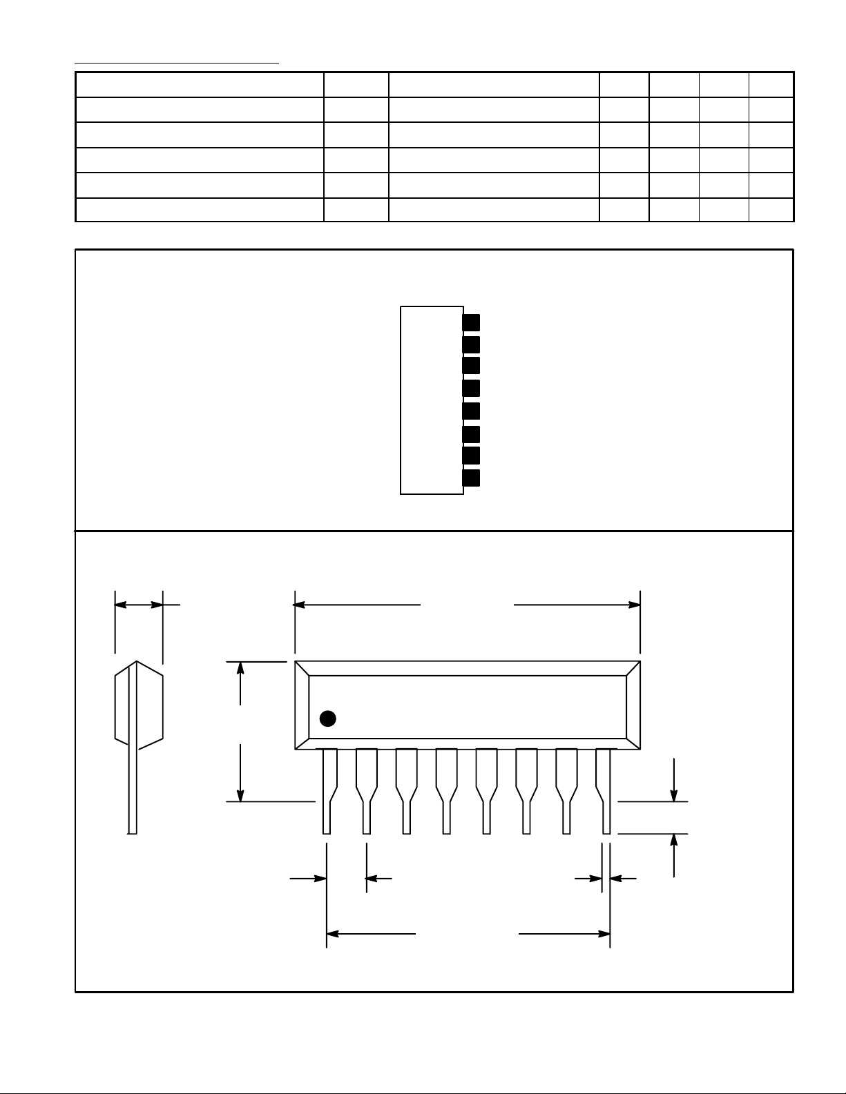
Pin Connection Diagram
(Front View)
V
8
CC
V
ON Mute
7
CC
Relay Detect
6
5
GND
AC OFF Detect
4
Switch for Latch/
3
Automatic Reset
Output Offset Detector
2
Overload Detector
1
.800 (20.3).142 (3.6)
.362
(9.2)
18
.100 (2.54)
.020 (0.50).100 (2.54)
.700 (17.78)
 Loading...