

NTE NTE7091 Datasheet
NTE7091
Integrated Circuit
Dual, Bi–Directional Motor Driver
Description:
The NTE7091 is an integrated circuit in a 10–Lead SIP type package designed for forward/reverse
direction select driver by switching motor 1 or motor 2 with a brush. Forward/reverse direction select
of motor 1 or motor 2 can be made by 3–bit input logic. It also assures five outputs of both brakes
and is suitable for VCR tape loading and cassette loading, video disc players, etc.
Features:
D Wide Range of Operating Supply Voltage: V
CC(opr)
D Forward and Reverse Drive of Motor 1 or Motor 2 by 3–Bit Input.
D Built–In Thermal Protection Circuit.
= 4V to 20V
Absolute Maximum Ratings:
Supply Voltage (1), V
Supply Voltage (2), V
Supply Current (1), I
Input Voltage, V
CC1
CC2
CC1
I
Motor Rush Allowable Current, I
Motor Ordinal Current, I
Power Dissipation, P
O
D
(TA = +25°C unless otherwise specified)
OP
Operating Ambient Temperature Range, T
Storage Temperature Range, T
Electrical Characteristics:
Parameter Symbol Test Conditions Min Typ Max Unit
Supply Current I
Output Leakage Current I
Low Level Output Voltage V
High Level Output Voltage V
Output Offset Voltage V
8–Pin Output Current I
stg
(TA = +25°C unless otherwise specified)
CC1
O(leak)VCC1
OH
O(offset)VR
V4 = V5 = V6 = 1V, IO = 0mA,
V
V
IOL = 500mA – – 1.5 V
OL
IOH = –500mA 10 – – V
VR = 6V, IOH = –500mA –1.4 – –0.6 mA
R
–0.5 to +24V. . . . . . . . . . . . . . . . . . . . . . . . . . . . . . . . . . . . . . . . . . . . . . . . . . . .
–0.5 to +24V. . . . . . . . . . . . . . . . . . . . . . . . . . . . . . . . . . . . . . . . . . . . . . . . . . . .
–0.5 to V
±600mA. . . . . . . . . . . . . . . . . . . . . . . . . . . . . . . . . . . . . . . . . . . . . . . . . . . . . . . .
1100mW. . . . . . . . . . . . . . . . . . . . . . . . . . . . . . . . . . . . . . . . . . . . . . . . . . . . . . . . .
opr
–20° to +75°C. . . . . . . . . . . . . . . . . . . . . . . . . . . . . . . . . .
–55° to +150°C. . . . . . . . . . . . . . . . . . . . . . . . . . . . . . . . . . . . . . . . . .
– 7 20 mA
= V
CC1
= V
= 0 or 20V
O
= 6V, IOH = –500mA –0.5 – +0.5 V
= 12V
CC2
= 20V, Output Open,
CC2
– – ±100 µA
20mA. . . . . . . . . . . . . . . . . . . . . . . . . . . . . . . . . . . . . . . . . . . . . . . . . . . . . . . . . . .
CC1
±1.6A. . . . . . . . . . . . . . . . . . . . . . . . . . . . . . . . . . . . . . . . . . . . . . . . .
V. . . . . . . . . . . . . . . . . . . . . . . . . . . . . . . . . . . . . . . . . . . . . . . . . . . . . . . . . .
Note 1. Operating Supply Voltage Range: V
CC(opr)
= 4V to 20V
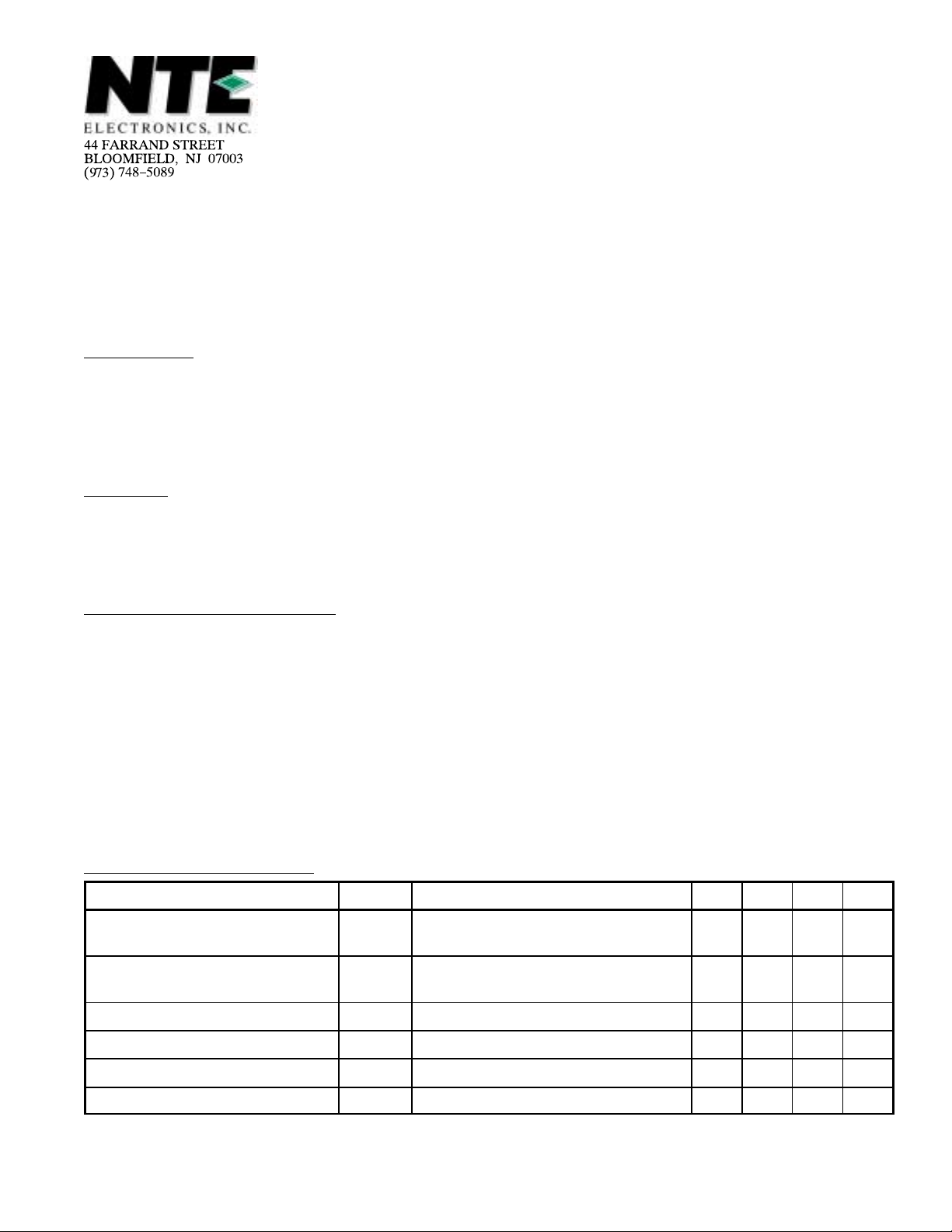
Pin Connection Diagram
(Front View)
10
9
8
7
6
5
4
3
2
1
Output 1
V
V
V
Input 3
Input 2
Input 1
Output 3
Output 2
GND
CC2
R
CC1
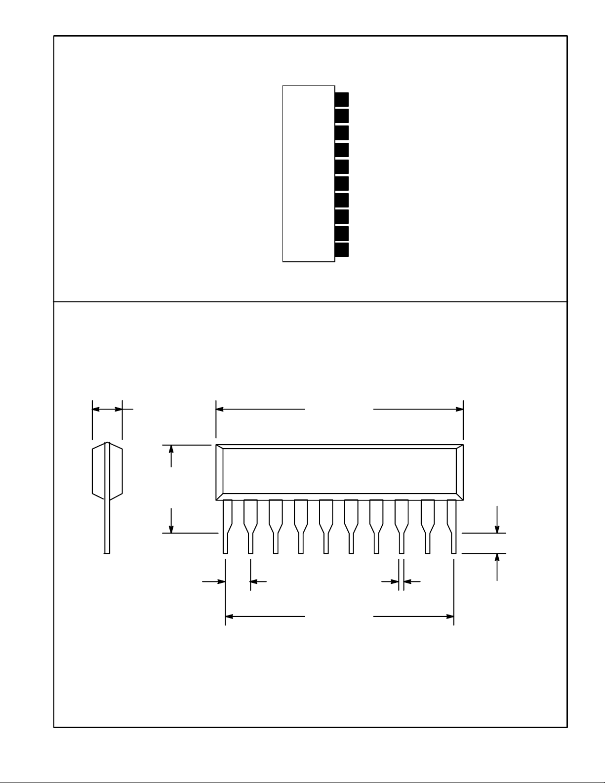
.110 (2.8)
.326
(8.28)
Max
.992 (25.2)
110
.019 (0.48).100 (2.54)
.118
(3.0)
.900 (22.8)
Min
 Loading...