

NTE NTE7084 Datasheet

NTE7084
Integrated Circuit
Color TV Sync Deflection Circuit
Description:
The NTE7084 is an IC containing not only the main functions required to achieve synchronization and
deflection in color television receivers but also a generator of horizontal, vertical blanking pulses, and
a generator of burst gate pulses (sandcastle type) in an 18–Lead DIP type package. This is a multifunctional device ideally suited for use in color television receivers aiming at high–quality picture reproduction.
Functions:
D Synchronizing Separation
D Vertical Drive
D X–Ray Protection
D Sandcastle Pulse (Burst Gate Pulse + Horizontal Blanking Pulse)
D Composite Blanking Pulse (Vertical + Horizontal Blanking Pulse)
Features:
D Horizontal and Vertical Oscillations are Stable Against Variations in Ambient Temperature and
Supply Voltage due to Small Warm–Up Drift.
D Small Variation in Horizontal Oscillation Frequency
D Good Linearity and Interlace because D C Bias at Vertical Output Stage is Subjected to Sampling
Control Within Retrace Time.
D Vertical Blanking Pulse Width can be set freely by Peripheral Parts.
D Minimized Picture Distortion because AFC Circuit is Defeated During Vertical Trigger Pulse Input
Period.
D Multifunctional and Compact
D Vertical Oscillation
D Horizontal AFC
D Horizontal Oscillation
Absolute Maximum Ratings: (TA = +25°C unless otherwise specified)
Maximum Supply Voltage, V
Maximum Current Dissipation, I
Maximum Applied Voltage, V
CC14
CC18
11
Allowable Power Dissipation (TA ≤ +65°C), PDmax 570mW. . . . . . . . . . . . . . . . . . . . . . . . . . . . . . . . . . .
Operating Temperature Range, T
Storage Temperature Range, T
stg
opr
–20° to +85°C. . . . . . . . . . . . . . . . . . . . . . . . . . . . . . . . . . . . . . . . .
–55° to +125°C. . . . . . . . . . . . . . . . . . . . . . . . . . . . . . . . . . . . . . . . . .
Recommended Operating Conditions: (TA = +25°C unless otherwise specified)
Recommended Supply Voltage, V
CC14
14V. . . . . . . . . . . . . . . . . . . . . . . . . . . . . . . . . . . . . . . . . . . . . . . . . . . . .
16mA. . . . . . . . . . . . . . . . . . . . . . . . . . . . . . . . . . . . . . . . . . . . . . . .
–6V. . . . . . . . . . . . . . . . . . . . . . . . . . . . . . . . . . . . . . . . . . . . . . . . . . . . . . .
12V. . . . . . . . . . . . . . . . . . . . . . . . . . . . . . . . . . . . . . . . . . . . . . . .
Electrical Characteristics: (TA = +25°C, V
= 12V unless otherwise specified)
CC14
Parameter Symbol Test Conditions Min Typ Max Unit
V
Current Dissipation I
CC14
V
Supply Voltage V
CC18
CC14
CC18
13.5 – 29.0 mA
11.8 – 13.2 V
Zener Bias Minimum Current – – 13 mA
Sync Separator Input DC Level 9.0 – 9.6 V
Sync Signal Peak Value 9.5 – 11.5 V
Burst Gate Pulse Peak Value (SCP) 9.5 – 11.5 V
Burst Gate Pulse Delay Time 1 (SCP) T
Burst Gate Pulse Delay Time 2 (SCP) T
BR
BF
– – 0.5 µs
3.6 – 4.2 µs
Horizontal Blanking Pulse Peak Value (SCP) 2.7 – 3.3 V
Horizontal Blanking Pulse Peak Value (CBP) I = 1mA 12.7 – 13.5 V
Vertical Blanking Pulse Peak Value (CBP) Load Resistance R = 33kΩ 7.2 – 8.2 V
Vertical Frequency Pull–In Range Vertical Sync 60Hz 9.0 – 11.0 Hz
Vertical Free–Running Frequency f
Supply Voltage Dependence of Vertical
VR1 = fv center 55Hz 50 – 60 Hz
v
V14 = 12V ±1V, 55Hz at 12V –0.5 – 0.5 Hz
Frequency
Middle Point Control Threshold Level 3.8 – 4.4 V
Vertical Blanking Threshold Level 5.0 – 5.7 V
Vertical Oscillation Start Voltage – – 4 V
Temperature Characteristic of Vertical
TA = –10° to +60°C –0.028 – 0.028 Hz/°C
Frequency
Vertical Driver Amplification Factor 12 – 17 dB
Horizontal AFCD.C Loop Gain +sign at V1 = 5V,
±0.6 – ±1.5 mA
–sign at V1 = 1V
Horizontal Free–Running Frequency f
fH center 15.73kHz –750 – 750 Hz
H
Horizontal Oscillation Start Voltage – – 4 V
Supply Voltage Dependence of Horizontal
Frequency
AFC Comparison
Sawtooth Wave Input
AFC Output
Time Constant Circuit
Horizontal Output
Vertical Drive
Sawtooth Wave Input
Vertical Output
Middle Point Voltage
VZ – VZ x 90% –50 – 50 Hz
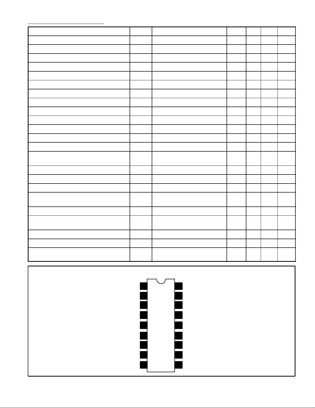
Pin Connection Diagram
1
2
3
18
+V
Composite Blanking
17
Pulse Output
Video Signal Input
16
(Positive)
4
5Holddown Input
6GND
7Vertical Drive Output
8
9
15
Time Constant Circuit
14
+V
Sandcastle Pulse
13
Output
Horiz, Vert Sync
12
Signal Output
Vertical Trigger Input
11
10
Time Constant Circuit
(Horizontal)
CC18
(Vertical)
CC14
 Loading...