

NTE NTE7082 Datasheet
NTE7082
Integrated Circuit
Stepper Motor Driver
Description:
The NTE7082 is a bipolar integrated circuit in a 16–Lead DIP type package intended for driving a four–
phase two–state motor. The circuit consists of a bidirectional four–state counter and a code converter
to drive the four outputs in the sequence required for driving a stepping motor.
Features:
D High Noise Immunity Inputs
D Clockwise and Counter–Clockwise Operation
D Reset Facility
D High Output Current
D Outputs Protected Against Damage by Overshoot
Applications:
D Automotive Industry
D Industrial
D Office Equipment
D EDP
Absolute Maximum Ratings:
DC Supply Voltage, VCC1, VCC2 18V. . . . . . . . . . . . . . . . . . . . . . . . . . . . . . . . . . . . . . . . . . . . . . . . . . . . .
Input Voltage (All Inputs), V
Current into Pin4, I
Output Current, I
RX
OL
Operating Ambient Temperature Range, T
Storage Temperature Range, T
I
120mA. . . . . . . . . . . . . . . . . . . . . . . . . . . . . . . . . . . . . . . . . . . . . . . . . . . . . . . . . . . .
500mA. . . . . . . . . . . . . . . . . . . . . . . . . . . . . . . . . . . . . . . . . . . . . . . . . . . . . . . . . . . . . .
A
stg
–20° to +70°C. . . . . . . . . . . . . . . . . . . . . . . . . . . . . . . . . . .
–65° to +150°C. . . . . . . . . . . . . . . . . . . . . . . . . . . . . . . . . . . . . . . . . .
DC Electrical Characteristics: (VCC = 9.5V to 18V, VEE = 0V, TA = –20° to +70°C unless
otherwise specified)
Parameter Symbol Test Conditions Min Typ Max Unit
Supply Voltage Range V
Supply Current I
CC
CC
VCC1 = 12V, unloaded,
all outputs HIGH, Pin4 Open
8.5 – 18.0 V
2.0 4.5 6.5 mA
18V. . . . . . . . . . . . . . . . . . . . . . . . . . . . . . . . . . . . . . . . . . . . . . . . . . . . . . . . .
DC Electrical Characteristics (Cont’d): (VCC = 9.5V to 18V, VEE = 0V, TA = –20° to +70°C
unless otherwise specified)
Parameter Symbol Test Conditions Min Typ Max Unit
Count, Mode, and Reset Inputs (Pin15, Pin3, and Pin2)
HIGH Input Voltage V
LOW Input Voltage V
HIGH Input Current I
LOW Input Current I
IH
IL
IH
IL
7.5 – – V
– – 4.5 V
– 1 – µA
– 30 – µA
External Resistor (Pin4)
Voltage at External Resistor V
RX
VCC = 12V ±15%, R4 = 130Ω ±5% 3.0 – 4.5 V
Output 1, Output 2, Output 3, and Output 4 (Pin6, Pin8, Pin9, and Pin11)
LOW Output Voltage V
OL
IOL = 350mA – 500 1000 mV
IOL = 500mA – 700 – mV
LOW Output Current I
HIGH Output Current I
OL
OH
VO = 18V – – 50 µA
– – 500 mA
Mode Input Table:
With the Mode Input (Pin3) the sequence of output signals, and hence the direction of rotation of the
stepping motor, can be chosen as shown below:
Counting
Sequence
Output 1 Output 2 Output 3 Output 4 Output 1 Output 2 Output 3 Output 4
0 L H L H L H L H
Mode = LOW Mode = HIGH
1 H L L H L H H L
2 H L H L H L H L
3 L H H L H L L H
0 L H L H L H L H
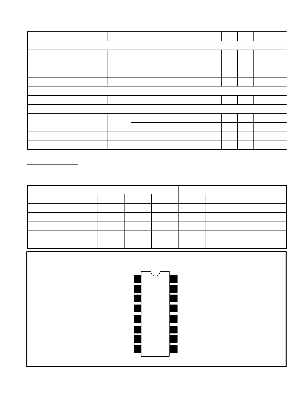
Pin Connection Diagram
N.C.
Reset Input
Mode Input
External Resistor
1
2
3
4
5GND
6Output 1
7N.C.
8Output 2
16
N.C.
15
Count Input
+VCC1
14
13
+VCC2
12 GND
11 Output 4
N.C.
10
Output 3
9
 Loading...