

NTE NTE7063 Datasheet

NTE7063
Integrated Circuit
CRT Display Synchronization Deflection Circuit
Description:
The NTE7063 is a sync–deflection circuit IC dedicated to CRT display use. It can be connected to
the NTE1773, NTE1797, or the NTE1855 (for vertical output use) to form a sync–deflection circuit that
meets every requirement for CRT use.
So far, ICs for color TV use have been applied to the sync–deflection circuit for CR T display use and
general purpose ICs such as one–shot multivibrators, inverters, and a lot of transistors have been
used to form the peripherals such as sync input interface, horizontal phase shifter. The NTE7063 contains these peripherals on chip and adopts a stable circuit for horizontal oscillation from 15kHz to
100kHz aiming at improving the characteristics required for CRT display use.
The NTE7063 has independent GND pins for the horizontal block and vertical block, thus facilitating
pattern layout for applications where the NTE7063 is used at high frequencies.
Features:
D The Vertical Pull–In Range is Approximately 10Hz at fV = 60Hz.
D The Horizontal Oscillation Frequency can be Adjusted Stably from 15kHz to 100kHz.
D The Horizontal Display can be Shifted Right/Left.
D The Horizontal/Vertical Sync Input can be Used Intact Regardless of the Difference in Pulse
Polarity and Pulse Width.
D The AFC Feedback Sawtooth Wave can be Obtained by Simply Applying a Flyback Pulse to
the IC as a Trigger Pulse.
D Any Duty of the Horizontal Pulse can be Set.
D Good Vertical Linearity because DC Bias at Vertical Output Stage is Subjected to Sampling
Control Within Retrace Time.
D Excellent Interlace and Vertical Jitter Characteristics on the High–Definition Display Because
of Independent GND Pins for the Horizontal Block and Vertical Block.
On–Chip Functions:
Horizontal Block
D AFC
D Horizontal OSC
D X–Ray Protector
D Horizontal Phase Shifter
D AFC Sawtooth Wave Generator
D Horizontal Pulse Duty Setting
Vertical Block
D Vertical OSC
D Vertical Sawtooth Wave Generator
D Sampling Type DC Voltage Control
Absolute Maximum Ratings: (TA = +25°C unless otherwise specified)
Maximum Supply Voltage, V11, V
22
Allowable Power Dissipation (TA ≤ +65°C), Pdmax 780mW. . . . . . . . . . . . . . . . . . . . . . . . . . . . . . . . . . .
Operating Temperature Range, T
Storage Temperature Range, T
stg
opr
–20° to +85°C. . . . . . . . . . . . . . . . . . . . . . . . . . . . . . . . . . . . . . . . .
–65° to +125°C. . . . . . . . . . . . . . . . . . . . . . . . . . . . . . . . . . . . . . . . . .
Operating Conditions: (TA = +25°C unless otherwise specified)
Recommended Supply Voltage, V
Operating Voltage Range, V
11
Recommended Vertical Pulse Input Peak Value, V
Operating Vertical Pulse Input Peak Value Range, V
Recommended Horizontal Pulse Input Peak Value, H
Operating Horizontal Pulse Input Peak Value Range, H
, V
22
11
, V
22
PULSE
PULSE
PULSE
. . . . . . . . . . . . . . . . . . . . . . . . . . . . . .
. . . . . . . . . . . . . . . . . . . . . . . . .
. . . . . . . . . . . . . . . . . . . . . . . . . . . .
PULSE
. . . . . . . . . . . . . . . . . . . . . .
9 to 13.5V. . . . . . . . . . . . . . . . . . . . . . . . . . . . . . . . . . . . . . . . . . . . .
2 to 6V
2 to 6V
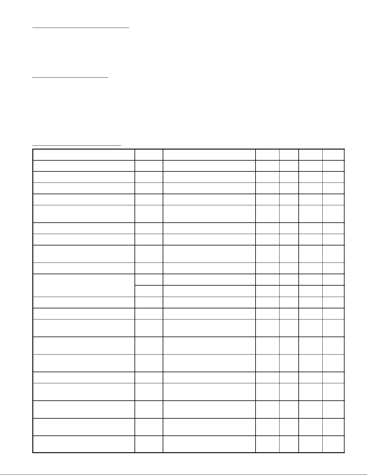
Electrical Characteristics: (TA = +25°C, V11, V22 = 12V unless otherwise specified)
Parameter Symbol Test Conditions Min Typ Max Unit
V
Current Dissipation I
CC11
V
Current Dissipation I
CC22
Vertical Frequency Pull–In Range V
Vertical Free–Running Frequency f
Increased/Reduced Voltage Charac-
teristic of Vertical Frequency
∆f
11
22
PIN
V
VV
Vertical Sync 60Hz 10 – 12 Hz
fv center 55Hz 50 – 60 Hz
V22 = 12V ±1V, 55Hz at 12V –0.1 – 0.1 Hz
12 – 30 mA
5 – 12 mA
5V
5V
14V. . . . . . . . . . . . . . . . . . . . . . . . . . . . . . . . . . . . . . . . . . . . . . . . . . .
12V. . . . . . . . . . . . . . . . . . . . . . . . . . . . . . . . . . . . . . . . . . . . . .
P–P
P–P
P–P
P–P
Midpoint Control Threshold Level 3.8 – 4.4 V
Vertical OSC Start Voltage F
Temperature Characteristic of Vertical
Frequency
Vertical Driver G
Amplification Factor Horizontal AFC
DC Loop Gain
Horizontal Free–Running Frequency f
Horizontal OSC Start Voltage f
Increased/Reduced Voltage Charac-
teristic of Horizontal Frequency
Horizontal OSC Warm–Up Drift ∆f
Temperature Characteristic of Hori-
zontal Frequency
Horizontal Output Drive Current I
Increased/Reduced Voltage Charac-
teristic of Phase Shifter Delay Time
I
AFC
I
AFC
∆f
vst
TA = –10° to +60°C –0.028 – 0.028 Hz/°C
V
+ +0.85 – +1.6 mA
– –1.6 – –0.85 mA
fH center 15.734kHz –750 – 750 Hz
H
Hst
V11 = 12V ±1V, 15.734kHz at 12V –50 – +50 Hz
HV
5sec to 30min after application of
H
power
TA = –10° to +60°C –2.9 – +2.9 Hz/°C
13
V11 = 12V ±1V –0.5 – 0.5 %/V
– – 4.0 V
12 – 18 dB
– – 4.0 V
–50 – +50 Hz
6 – 12 mA
Temperature Characteristic of
Phase Shifter Delay Time
Increased/Reduced Voltage Charac-
teristic of Phase Shifter Delay Time
Temperature Characteristic of
Phase Shifter Pulse Width
TA = –10° to +60°C –0.1 – 0.1 %/°C
V11 = 12V ±1V –1.0 – 1.0 %/V
TA = –10° to +60°C –0.13 – 0.13 %/°C
 Loading...