

NTE NTE7053 Datasheet

NTE7053
Integrated Circuit
22W Bridge–Stereo Amplifier
for Car Radio
Description:
The NTE7053 is an audio power amplifier is a 11–Lead Staggered SIP type package designed for car
radio applications.
Thanks to the fully complementary PNP/NPN output configuration, the high performance of this device is obtained without bootstrap capacitors.
A delay turn–on mute circuit eliminates audible ON/OFF noise, and a novel short circuit protection
system prevents spurious intervention with highly inductive loads.
Features:
Protections:
D Few External Components
D Output AC–DC Short Circuit to GND and to
D No Boucherot Cells
D No Bootstrap Capacitors
D High Output Power
D No Switch ON/OFF Noise
D Very Low Stand–by Current
D Fixed Gain (30dB Stereo)
D Very Inductive Loads
D Loudspeaker Protection
D Overrating Chip Temperature
D Load Dump Voltage
D Fortuitous Open Ground
D Programmable Turn–On Delay
Absolute Maximum Ratings:
Operating Supply Voltage, V
DC Supply Voltage, V
S
Peak Supply Voltage (for t = 50ms), V
S
S
Output Peak Current (Non–Repetitive for t = 100µs), I
Output Peak Current (Repetitive Frequency > 10Hz), I
Power Dissipation (TC = +85°C), P
Junction Temperature Range, T
Storage Temperature Range, T
tot
J
stg
Maximum Thermal Resistance, Junction–to–Case, R
Supply Voltage
O
O
thJC
18V. . . . . . . . . . . . . . . . . . . . . . . . . . . . . . . . . . . . . . . . . . . . . . . . . . . . . . . .
28V. . . . . . . . . . . . . . . . . . . . . . . . . . . . . . . . . . . . . . . . . . . . . . . . . . . . . . . . . . . . . .
40V. . . . . . . . . . . . . . . . . . . . . . . . . . . . . . . . . . . . . . . . . . . . . . .
5A. . . . . . . . . . . . . . . . . . . . . . . . . . . . . . . . . .
4A. . . . . . . . . . . . . . . . . . . . . . . . . . . . . . . . . .
36W. . . . . . . . . . . . . . . . . . . . . . . . . . . . . . . . . . . . . . . . . . . . . . . . .
–40° to +150°C. . . . . . . . . . . . . . . . . . . . . . . . . . . . . . . . . . . . . . . . . . .
–40° to +150°C. . . . . . . . . . . . . . . . . . . . . . . . . . . . . . . . . . . . . . . . . .
1.8°C/W. . . . . . . . . . . . . . . . . . . . . . . . . . . .
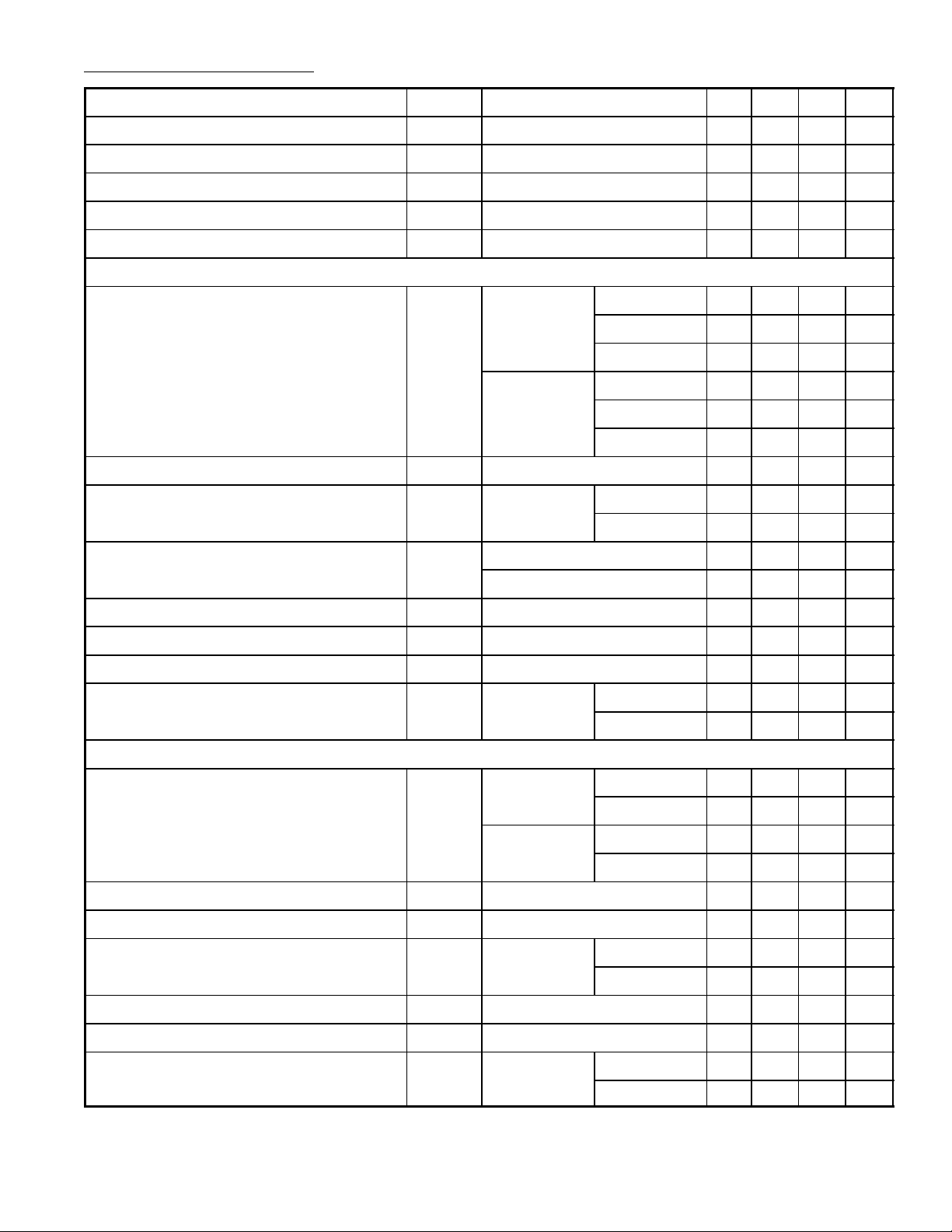
Electrical Characteristics: (TA = +25°C, VS = 14.4V, f = 1kHz unless otherwise specified)
Parameter Symbol Test Conditions Min Typ Max Unit
Supply Voltage Range V
Total Quiescent Drain Current I
Stand–By Attenuation A
Stand–By Current I
Thermal Shut–Down Junction Tem perat ure T
d
SB
SB
sd
S
Stereo Configuration – – 120 mA
8 – 18 V
60 80 – dB
– – 100 µA
– 150 – °C
Stereo
Output Power (Each Channel) P
O
d = 10%
RL = 2Ω – 11 – W
RL = 3.2Ω 7 8 – W
RL = 4Ω – 8.5 – W
d = 10%,
VS = 13.2V
RL = 2Ω – 9 – W
RL = 3.2Ω – 6.5 – W
RL = 4Ω – 5.5 – W
Distortion d PO = 0.1W to 4W, RL = 3.2Ω – – 0.5 %
Supply Voltage Rejection SVR
RS = 10kΩ,
f = 100Hz
C3 = 22µF 45 50 – dB
C3 = 100µF – 57 – dB
Crosstalk CT f = 1kHz 45 55 – dB
f = 10kHz – 50 – dB
Input Resistance R
Voltage Gain G
Voltage Gain Match G
Input Noise Voltage E
IN
I
V
V
Note 1
RS = 50Ω – 2 – µV
30 50 – kΩ
27 29 31 dB
– – 1 dB
RS = 10kΩ – 2.7 7 µV
Bridge
Output Power (Each Channel) P
O
d = 10%
RL = 3.2Ω 16 22 – W
RL = 4Ω – 20 – W
d = 10%,
VS = 13.2V
RL = 3.2Ω – 19 – W
RL = 4Ω – 17.5 – W
Distortion d PO = 0.1W to 4W, RL = 4Ω – – 1 %
Output Offset Voltage V
OS
Supply Voltage Rejection SVR
Input Resistance R
Voltage Gain G
Input Noise Voltage E
I
V
IN
RS = 10kΩ,
f = 100Hz
Note 1
C3 = 22µF 45 50 – dB
C3 = 100µF – 57 – dB
RS = 50Ω – 2.7 – µV
– – 250 mV
– 50 – kΩ
33 35 37 dB
RS = 10kΩ – 3.2 – µV
Note 1. 22Hz to 22kHz
 Loading...