

NTE NTE7044 Datasheet
NTE7044
Integrated Circuit
Switching Regulator Control Circuit
Description:
The NTE7044 is an integrated circuit in a 9–Lead SIP type package which contains a PWM switching
regulator control circuit and protect circuit on a single chip.
Features:
D Soft Start Circuit
D 0 to 0.7 Duty
D Protection Circuit for Overvoltage and Current
D External Trigger Available
D High Supply Voltage Protection
D Low Supply Voltage Protection
D Reference Voltage Provided by an External Zener Diode
Absolute Maximum Ratings:
Supply Voltage, V
CC
(TA = +25°C unless otherwise specified)
Circuit Voltage
V
6–5
V
, V2, V
1
V
3–5
V
7–5
V
, V
8
9–5
Supply Current, I
Circuit Current, I
Power Dissipation, P
Local Power Dissipation (Q
Operating Ambient Temperature Range, T
Storage Temperatuere Range, T
. . . . . . . . . . . . . . . . . . . . . . . . . . . . . . . . . . . . . . . . . . . . . . . . . . . . . . . . . . . .
4–5
6
. . . . . . . . . . . . . . . . . . . . . . . . . . . . . . . . . . . . . . . . . . . . . . . . . . . . .
4
D
), P
1
D
opr
stg
Note 1. + is flow–in current to the circuit, while – is flow–out current.
Electrical Characteristics:
Parameter Symbol Test Conditions Min Typ Max Unit
Total Circuit Current I
Oscillation Frequency f
Output Pulse Duty (Min) t
Output Pulse Duty (Max) t
(TA = +25°C, VCC = 12V unless otherwise specified)
tot
OSC
w(duty)
w(duty)
14V. . . . . . . . . . . . . . . . . . . . . . . . . . . . . . . . . . . . . . . . . . . . . . . . . . . . . . . . . . . . . . . .
0V to 14.4V. . . . . . . . . . . . . . . . . . . . . . . . . . . . . . . . . . . . . . . . . . . . . . . . . . . . . . . . . . . . . . . . .
0 to V
3V to 10V. . . . . . . . . . . . . . . . . . . . . . . . . . . . . . . . . . . . . . . . . . . . . . . . . . . . . . . . . . . . . . . . . . .
0V to 8V. . . . . . . . . . . . . . . . . . . . . . . . . . . . . . . . . . . . . . . . . . . . . . . . . . . . . . . . . . . . . . . . . . . .
–3V to +4V. . . . . . . . . . . . . . . . . . . . . . . . . . . . . . . . . . . . . . . . . . . . . . . . . . . . . . . . . . . . . .
18mA. . . . . . . . . . . . . . . . . . . . . . . . . . . . . . . . . . . . . . . . . . . . . . . . . . . . . . . . . . . . . . . .
–1mA to +50mA
peak
260mW. . . . . . . . . . . . . . . . . . . . . . . . . . . . . . . . . . . . . . . . . . . . . . . . . . . . . . . . . .
60mW. . . . . . . . . . . . . . . . . . . . . . . . . . . . . . . . . . . . . . . . . . . . . . . . . . .
–20° to +75°C. . . . . . . . . . . . . . . . . . . . . . . . . . . . . . . . . .
–55° to +150°C. . . . . . . . . . . . . . . . . . . . . . . . . . . . . . . . . . . . . . . . .
8.4 10.5 12.6 mA
14.0 14.8 15.6 kHz
67 72 77 %
– 0 0 %
6–5
Electrical Characteristics (Cont’d): (TA = +25°C, VCC = 12V unless otherwise specified)
Parameter Symbol Test Conditions Min Typ Max Unit
Output Saturation Voltage V
O(sat)I4
High Supply Voltage Protection V
Low Supply Voltage Protection V
Input Voltage, External Trigger Start V
Input Voltage, One–Shot Multi Start V
= 10mA – 0.10 0.30 V
I4 = 50mA – 0.62 1.00 V
HVP
LVP
t1
t2
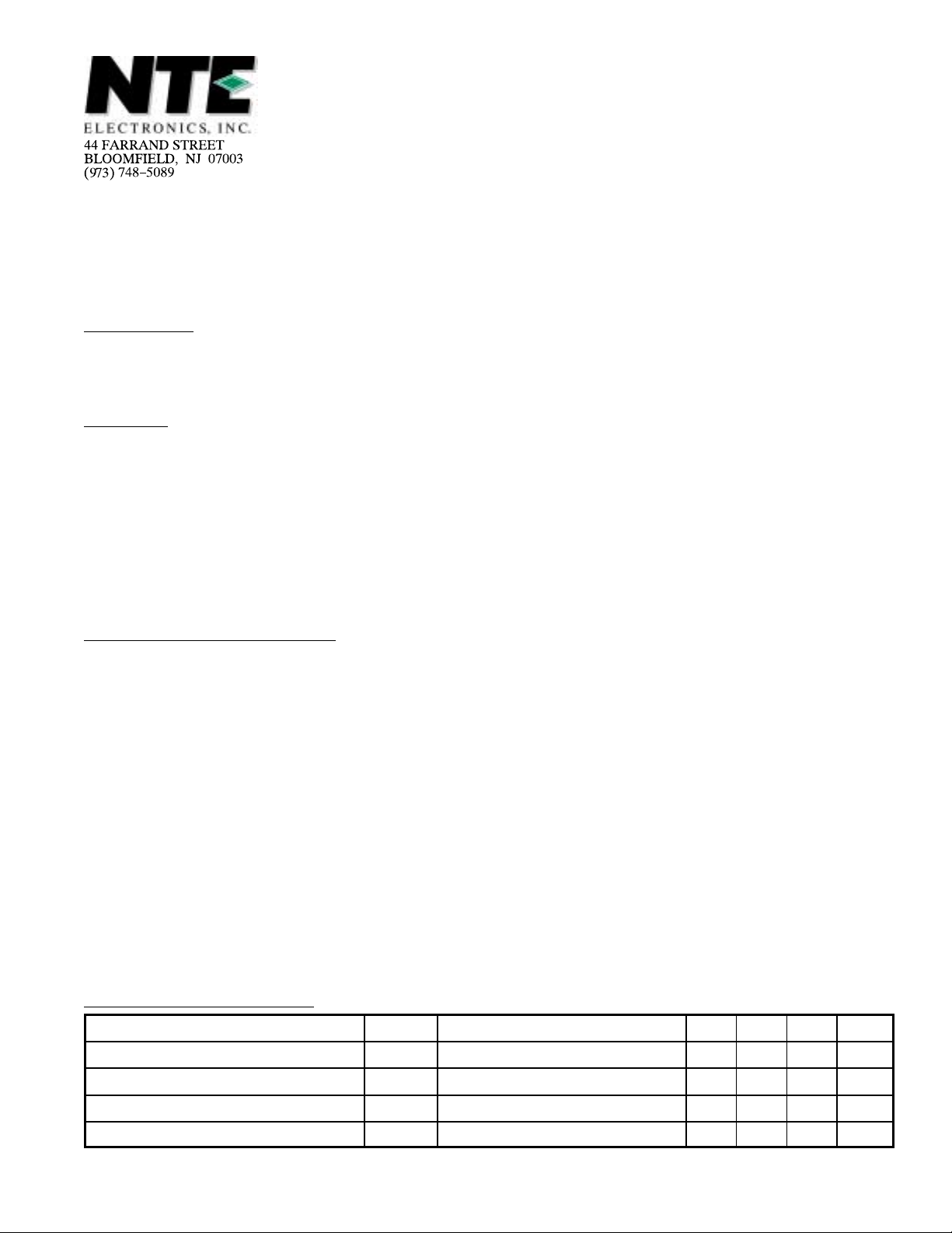
Pin Connection Diagram
(Front View)
Protector
9
8
Trigger
7
Soft Start
6
V
CC
5
GND
4
Output
3
Oscillator
2
Feedback
1
Reference Voltage
13.2 13.9 14.6 V
4.8 5.2 5.6 V
0.66 0.71 0.76 V
0.68 0.73 0.78 V
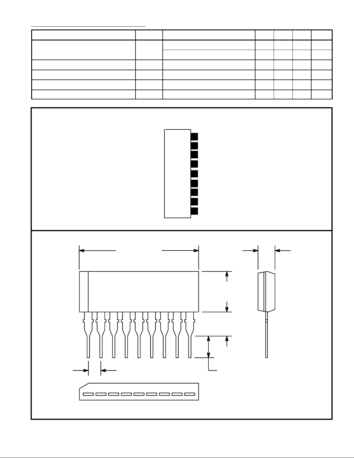
.929 (23.6) .118 (3.0)
.236
(6.0)
19
.098
(2.5)
.100 (2.54) .118(3.0)
 Loading...