

NTE NTE7042 Datasheet
NTE7042
Integrated Circuit
Bi–Directional Motor Driver
Description:
The NTE7042 is a Bi–Directional Motor Drive in a 9–Lead SIP type package and generates an output
current of 700mA (Max) with 4 output modes of forward rotation, reverse rotation, stop (idling), and
brake according to input logic (2 inputs). The GNDs of the logic unit and power unit are isolated.
Therefore, the circuit of a reversible, variable–speed motor can be easily composed by adding an
electronic governor at the output.
Features:
D Built–in Surge Absorbing Diode
D Low Standby Current
D Wide Operating Voltage Range: 4.5V to 15V
D TTL Compatible
D Built–in Thermal Shutdown Circuit
Absolute Maximum Ratings:
Supplu Voltage, V
Output Current, I
Power Dissipation, P
CC
O
D
(TA = +25°C unless otherwise specified)
Derate Above 25°C 8mW/°C. . . . . . . . . . . . . . . . . . . . . . . . . . . . . . . . . . . . . . . . . . . . . . . . . . . . . . .
Operating Temperature Range, T
Storage Temperature Range, T
Electrical Characteristics:
Parameter Symbol Test Conditions Min Typ Max Unit
Supply Voltage V
Supply Current I
Standby Current I
High Level Input Voltage V
Low Level Input Voltage V
High Level Input Current I
Collector–Emitter Voltage V
stg
(VCC = 9V, TA = +25°C unless otherwise specified)
CC1
V
CC2
CC1
I
CC2
standby
IH
IL
IH
CE
700mA. . . . . . . . . . . . . . . . . . . . . . . . . . . . . . . . . . . . . . . . . . . . . . . . . . . . . . . . . . . . . . .
800mW. . . . . . . . . . . . . . . . . . . . . . . . . . . . . . . . . . . . . . . . . . . . . . . . . . . . . . . . . .
opr
–20° to +60°C. . . . . . . . . . . . . . . . . . . . . . . . . . . . . . . . . . . . . . . . .
–55° to +125°C. . . . . . . . . . . . . . . . . . . . . . . . . . . . . . . . . . . . . . . . . .
VCC (Pin6) ∼ GND (Pin2, Pin5) 4.5 – 15 V
VCC (Pin6) ∼ COM (Pin8) 4.0 – 15 V
Pin1 “H”, Pin3 “L” or Pin1 “L”, Pin3 “H”,
= ∞
R
L
Pin1 “H”, Pin3 “L”, RL = ∞ 34 52 70 mA
Pin1 “L”, Pin3 “L” – – 1.5 mA
VIN = 2V – 93 135 µA
IO = 200mA – 1.2 1.6 V
18 34 50 mA
2.0 – – V
– – 0.8 V
18V. . . . . . . . . . . . . . . . . . . . . . . . . . . . . . . . . . . . . . . . . . . . . . . . . . . . . . . . . . . . . . . .
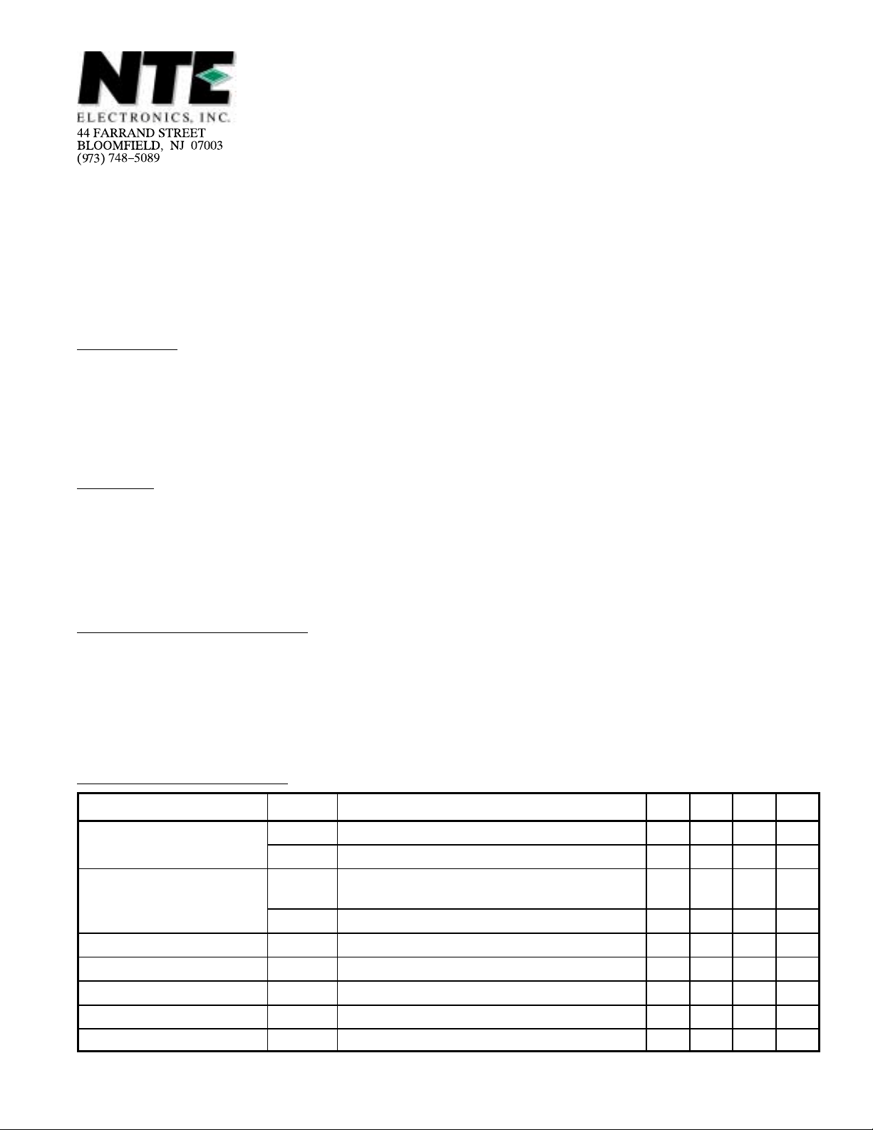
Truth Table:
Input
(Pin3)
Input
(Pin1)
Output
(Pin7)
Output
(Pin9)
IC not Operating L L Open Open
Motor Forward H L H L
Motor Reverse L H L H
Brake H H L L
Note 1. Input Voltage Level “H”: ±2.0V
Input Voltage Level “L”: ±0.8V
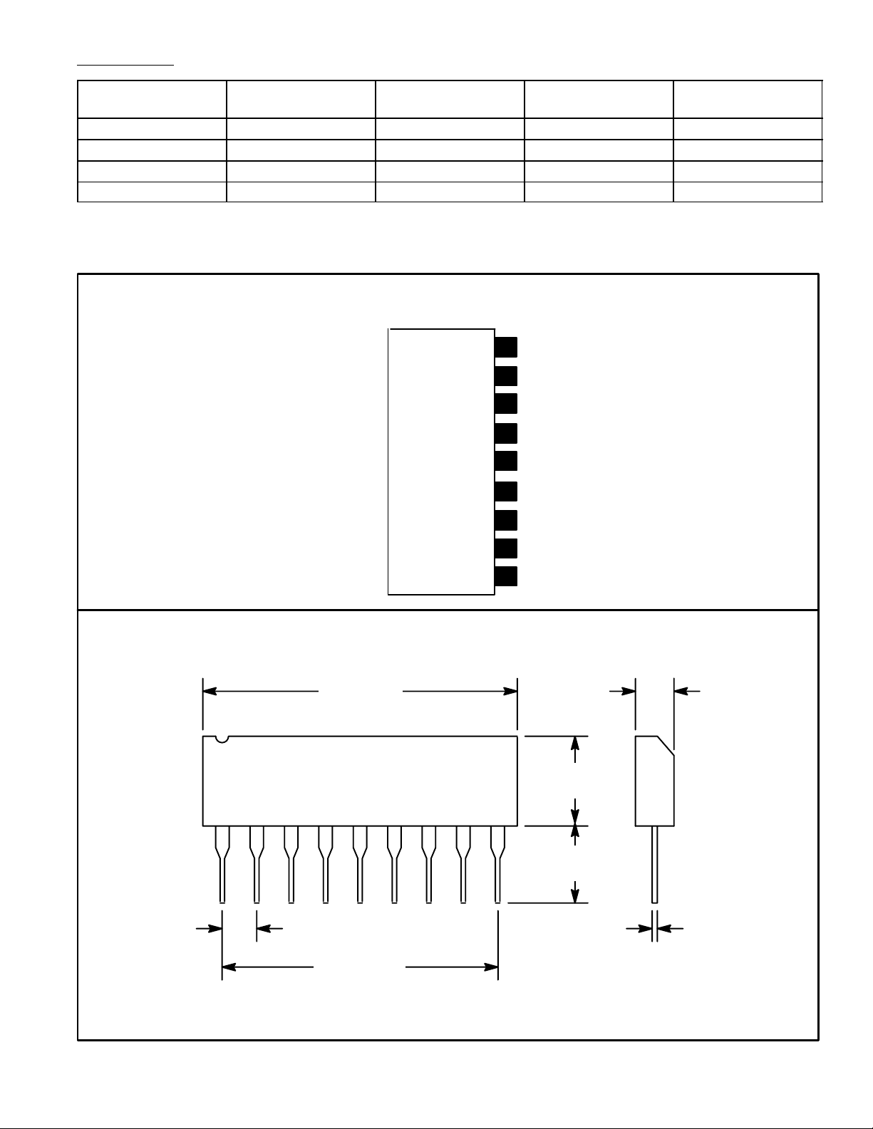
Pin Connection Diagram
(Front View)
Output 1
9
8
C
ON
7
Output 2
V
6
CC
5 GND
4
N.C.
Forward Input
3
2
GND
1
Reverse Input
.870 (22.0)
19
.110 (2.8)
.235
(6.0)
.195
(5.0)
.012 (0.30).100 (2.54)
.800 (20.32)
 Loading...