

NTE NTE7010 Datasheet
NTE7010
Integrated Circuit
Single Chip NTSC Color TV
Processor w/OSD Interface
Description:
The NTE7010 combines all the functions required for an NTSC color TV system in a 54–Lead DIP
type package. This device includes PIF/SIF circuits, video/chroma/deflection circuits, chroma band
pass filters, red and green OSD interfaces, and 1 channel audio video switches.
PIF Circuits
D 3–Stage Variable–Gain PIF Amplification Stage
D High–Speed Response ACC with Dual Time Constants (Peak AGC)
D Single End AFT Output with Defeat Function
D RF Delay AGC Output (Reverse AGC)
D Sync. Negative Detected Video Output Polarity
D Internal Black/White Noise Inverter
SIF Circuits
D 3–Stage Limiter Amplification Stage
D Quadrature FM Detector Circuit with Sound Mute Function
D 1 Channel External Audio Input
D High–Performance Electronic Attenuator Circuit
D Preamplifier Circuit
Video Circuit
D 2nd Order–Differential–Type Picture Sharpness Circuit (DC Control)
D Contrast Control with Unicolor Function
D Brightness Control with Pedestal Clamping Circuit (Variable DC Restoration Ratio)
D External Video Input
Chroma Circuit
D Internal 1/2 fsc Trap
D Internal Band Pass Filter
D ACC Circuit
D Color Control Circuit
D Unicolor Control Circuit
D Color Differential Output
D Tint Control Circuit
D Adjustment–Free APC Circuit
Deflection Circuits
D High–Performance Sync Separation Circuit
D Adjustment–Free Horizontal Oscillation Circuit
D Stable Vertical Synchronization
D Sawtooth–Type AFC (Internal Sawtooth Wave Generator)
D Horizontal Predrive Output
D X–Ray Protection Circuit
D Vertical NFB Amplification Circuit
OSD Interface (R, G Inputs)
D Directly Driven by µ–computer
Absolute Maximum Ratings: (TA = +25°C unless otherwise specified)
Power Supply Voltage, V
Internal Pin Voltage, V
in
Input Signal Amplitude, e
Power Dissipation, P
D
CC
GND –0.3V to VCC +0.3V. . . . . . . . . . . . . . . . . . . . . . . . . . . . . . . . . . . . . . . . . .
. . . . . . . . . . . . . . . . . . . . . . . . . . . . . . . . . . . . . . . . . . . . . . . . . . . . . . . .
in
4V
1.92W. . . . . . . . . . . . . . . . . . . . . . . . . . . . . . . . . . . . . . . . . . . . . . . . . . . . . . . . . . . .
13V. . . . . . . . . . . . . . . . . . . . . . . . . . . . . . . . . . . . . . . . . . . . . . . . . . . . . . . . . .
P–P
Derate Above 25°C 15.3mW/°C. . . . . . . . . . . . . . . . . . . . . . . . . . . . . . . . . . . . . . . . . . . . . . . . . . . .
Operating Temperature Range, T
Storage Temperature Range, T
stg
opr
–20° to +65°C. . . . . . . . . . . . . . . . . . . . . . . . . . . . . . . . . . . . . . . . .
–55° to +150°C. . . . . . . . . . . . . . . . . . . . . . . . . . . . . . . . . . . . . . . . . .
Note 1. CAUTION! This device is easily damaged by high static voltage or electric fields so extreme
care should be used when handling.
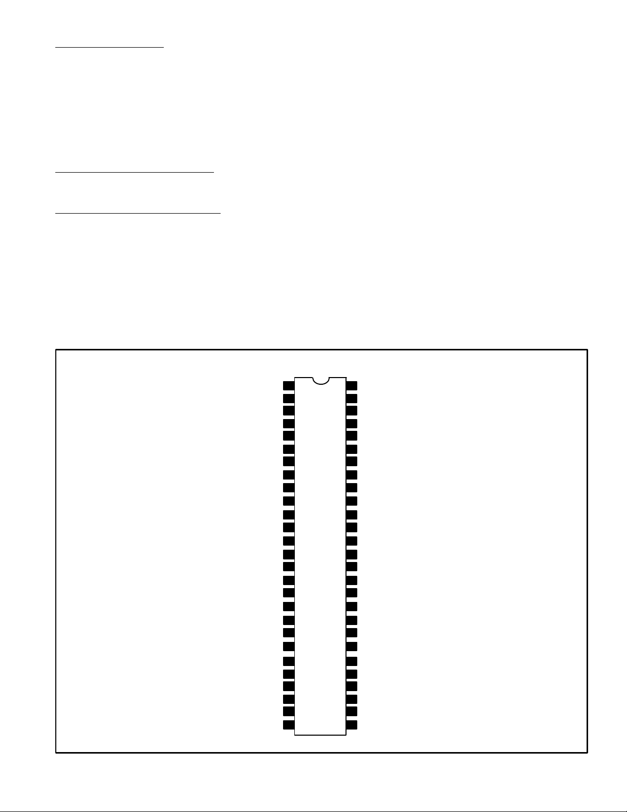
Pin Connection Diagram
Audio Output
RF AGC Output
RF AGC Delay
SIF T ank
st
AGC
1
External Audio Input
Horizontal Output
nd
AGC
2
PIF/SIF GND
PIF Input (1)
PIF Input (2)
fc Adjustment
APC Filter
3.58 X’tal
V/C/D V
R–Y Output
Y Output
G–Y Output
B–Y Output
R OSD Input
G OSD Input
FBP Input
X–Ray
Horizontal AFC
32fH VCO
H. V
Vertical Output
1
2
3
4
5
6
7
8 47
9 46
10 45
11 44
12 43
13
14
CC
15
16 39
17 38
18 37
19 36
20 35
21 34
22
23
24
25
26
CC
27
54
Audio Control
53
Audio TV Input
52
DE–Emphasis
51
SIF Input
50
AFT Output
49
AFT Tank
48
PIF T ank (2)
PIF T ank (1)
PIF/SIF V
42
41
40
33
32
31
30
29
28
CC
TV Detection Output
Tint Control
TV Input
Color Control
Contrast Control
External Video Input
V/C/O GND
Video Output
Vertical Sync Sep Filter
Brightness Control
Video Input
Sharpness Control
OSD Bright Control
SW for S–VHS
Chroma Input
Killer Filter
Vertical Ramp
Vertical NFB
 Loading...