

NTE NTE700 Datasheet
NTE700
Integrated Circuit
TV Chroma System
Description:
The NTE700 is a monolithic integrated circuit in a 16–Lead DIP type package that performs the functions of subcarrier regeneration, ACC and APC detection, and tint control in color television receivers.
It is designed to function compatibly with the NTE743 TV Chroma Amplifier/Demodulator in a 2–package chroma system.
The NTE700 is a TV Chroma System equivalent to the NTE982 except that the typical supply voltage
is +12V and no internal shunt regulator is incorporated.
Features:
D Voltage–Controlled Oscillator
D Keyed APC and ACC Detectors
D DC Hue Control
D Operates From +12V
Absolute Maximum Ratings:
DC Supply Voltage 15V. . . . . . . . . . . . . . . . . . . . . . . . . . . . . . . . . . . . . . . . . . . . . . . . . . . . . . . . . . . . . . . . .
Device Dissipation (Up to T
Derate Linearly Above +55°C 6.6mW/°C. . . . . . . . . . . . . . . . . . . . . . . . . . . . . . . . . . . . . . . . . . . .
Operating Ambient Temperature Range –40° to +85°C. . . . . . . . . . . . . . . . . . . . . . . . . . . . . . . . . . . . . .
Storage Temperature Range –65° to +150°C. . . . . . . . . . . . . . . . . . . . . . . . . . . . . . . . . . . . . . . . . . . . . . .
Lead Temperature (During Soldering, 1/16” from case, 10sec max) +265°C. . . . . . . . . . . . . . . . . . . .
= +55°C) 630mW. . . . . . . . . . . . . . . . . . . . . . . . . . . . . . . . . . . . . . . . . . . .
A
Electrical Characteristics:
Parameter Symbol Test Conditions Min Typ Max Unit
Static Characteristics
Supply Current I+ 12 – 24 mA
Oscillator Current I
ACC Output Balance Measure Pin15 to Pin16 –330 – 300 mV
APC Output Balance Measure Pin11 to Pin12 –450 – 450 mV
Oscillator Balance Measure Pin7 to Pin8 –330 – 330 mV
(TA = +25°C, V+ = 12V unless otherwise specified)
2
4.25 – 8.55 mA
Electrical Characteristics (Cont’d): (TA = +25°C, V+ = 12V unless otherwise specified)
Parameter Symbol Test Conditions Min Typ Max Unit
Dynamic Characteristics (eIN = 0.4V
Oscillator Center Frequency f
Sine Wave)
P–P
O
Set R for fO = 3.579545 ±5Hz – – – Hz
Oscillator Frequency Deviation fO1 –400 – 400 Hz
Oscillator Frequency Deviation |∆fO| V+ = 12V ±1V – – 175 Hz
Oscillator Pull–In Range, High Side Osc. must pull–in and lock to eIN at:
f
= 3.579745MHz
IN
Oscillator Pull–In Range, Low Side Osc. must pull–in and lock to eIN at:
f
= 3.579345MHz
IN
Dynamic ACC Measure Pin15 to Pin16, Record value
200 – – Hz
–200 – – Hz
–75 – 75 mV
(V1)
ACC Control Measure Pin15 to Pin16,
f
= 3.579545MHz
IN
Record Value (V2) mV
∆ACC Control Limits for ∆ACC Control = V2 – V1 120 – 250
Dynamic APC Tap of R to GND 1 – 12 V
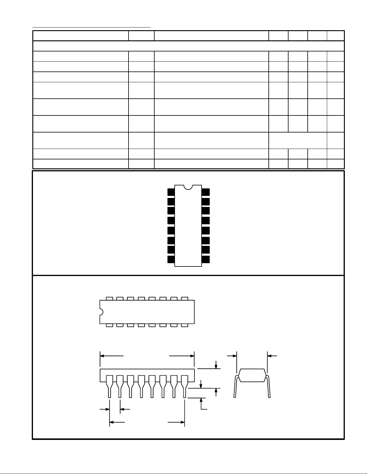
Pin Connection Diagram
Hue Control
OSC Output
OSC Output
Horiz Key Pulse Input
1
2
3
4
5GND
ACC Output
16
ACC Output
15
ACC Input
14
APC Input
13
12 APC Output
6OSC Input
7OSC Feedback Loop
8OSC Feedback Loop
11 APC Output
10 V (+)
9 N.C.
16 9
18
.260
.870 (22.0)
Max
(6.6)
Max
.200 (5.08)
Max
.100 (2.54)
.099 (2.5) Min
.700 (17.78)
 Loading...