

NTE NTE6850 Datasheet

NTE6850
Integrated Circuit
NMOS, Asynchronous Communications
Interface Adapter
Description:
The NTE6850 Asynchronous Communications Interface Adapter provides the data formatting and
control to interface serial asynchronous data communications information to bus organized systems
such as the NTE6800 Microprocessing Unit.
The bus interface of the NTE6850 includes select, enable, read/write, interrupt and bus interface logic
to allow data transfer over an 8–bit bidirectional data bus. The parallel data of the bus system is serially transmitted and received by the asynchronous data interface, with proper formatting and error
checking. The functional configuration of the ACIA is programmed via the data bus during system
initialization. A programmable control register provides variable word lengths, clock division ratios,
transmit control, receive control, and interrupt control. For peripheral or modem operation, three control lines are provided. These lines allow the ACIA to interface directly with the NTE6860 0–600 bps
digital modem.
Features:
D 8–Bit and 9–Bit Transmission
D Optional Even and Odd Parity
D Parity, Overrun and Framing Error Checking
D Programmable Control Register
D Optional ÷1, ÷16, and ÷64 Clock Modes
D Up to 1.0 Mbps Transmission
D False Start Bit Deletion
D Peripheral/Modem Control Functions
D Double Buffered
D One–Stop or Two–Stop Bit Operation
Absolute Maximum Ratings:
Supply Voltage, VCC –0.3 to +7.0V. . . . . . . . . . . . . . . . . . . . . . . . . . . . . . . . . . . . . . . . . . . . . . . . . . . . . .
Input Voltage, Vin –0.3 to +7.0V. . . . . . . . . . . . . . . . . . . . . . . . . . . . . . . . . . . . . . . . . . . . . . . . . . . . . . . . .
Operating Temperature Range, TA 0° to 70°C. . . . . . . . . . . . . . . . . . . . . . . . . . . . . . . . . . . . . . . . . . . . .
Storage Temperature Range, T
Thermal Resistance, Junction–to–Ambient, R
Note 1. This device contains circuitry to protect the inputs against damage due to high static voltages
or electric fields; however, it is advised that normal precautions be taken to avoid application
of any voltage higher than maximum rated voltages to this high impedance circuit. Reliability
of operation is enhanced if unused inputs are tied to an appropriate logic voltage level (e.g.
either VSS or VCC).
–55° to +150°C. . . . . . . . . . . . . . . . . . . . . . . . . . . . . . . . . . . . . . . . . .
stg
thJA
120°C/W. . . . . . . . . . . . . . . . . . . . . . . . . . . . . . . . . .
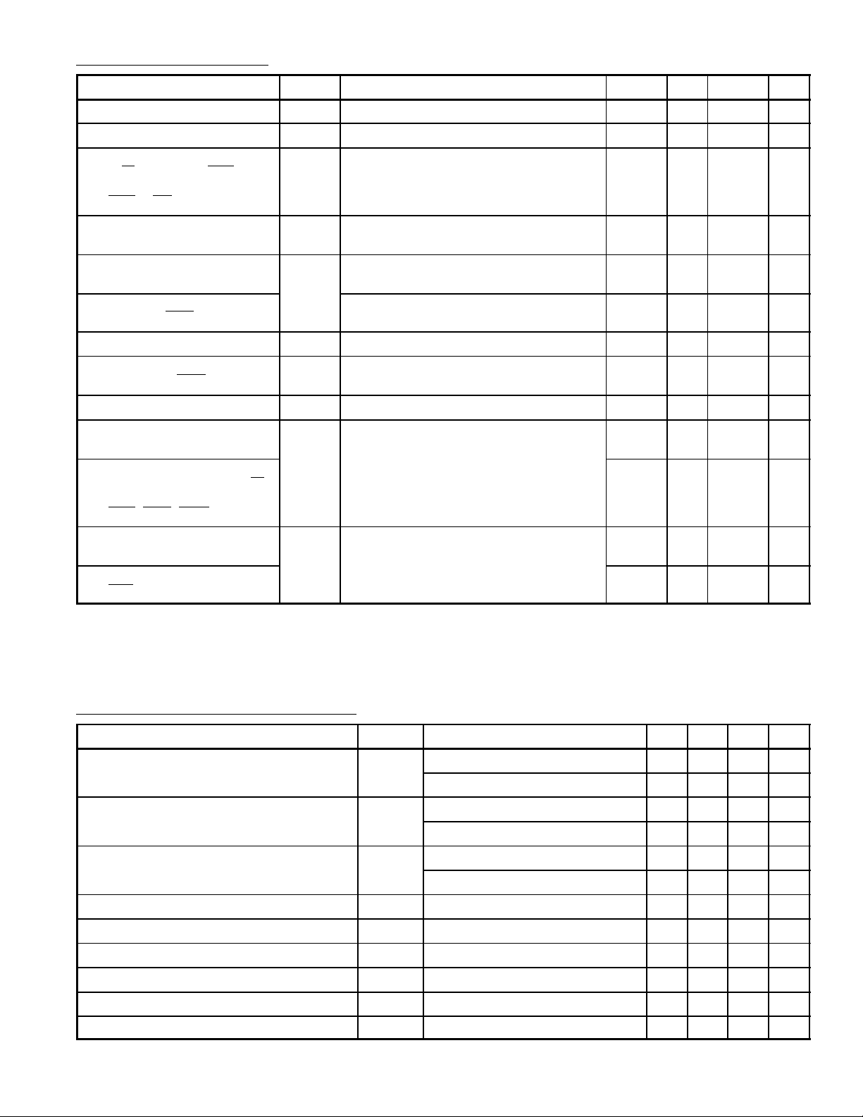
Electrical Characteristics: (VCC = 5V ± 5%, VSS = 0, TA = 0° to +70°C unless otherwise specified)
Parameter Symbol Test Conditions Min Typ Max Unit
Input High Voltage V
Input Low Voltage V
Input Leakage Current
IH
IL
I
Vin = 0 to 5.25V – 1.0 2.5 µA
in
VSS+2.0 – V
VSS–0.3 – VSS+0.8 V
R/W, CS0, CS1, CS2,
Enable, RS, RX D, RX C,
CTS, DCD
Hi–Z (Off–State) Input Current
I
Vin = 0.4 to 2.4V – 2.0 10.0 µA
TSI
D0 – D7
Output High Voltage
V
OHILoad
= 205µA, Enable Pulse Width < 25µs VSS+2.4 – – V
D0 – D7
Output High Voltage
TX Data, RTS
Output Low Voltage V
Output Leakage Current
I
LOH
I
= 100µA, Enable Pulse Width < 25µs VSS+2. – – V
Load
I
OL
= 1.6A, Enable Pulse Width < 25µs – – VSS+0.4 V
Load
VOH = 2.4V – 1.0 10 µA
(Off–State) IRQ
Internal Power Dissipation P
TA = 0°C, Note 2 – 300 525 mW
INT
Internal Input Capacitance
D0 – D7 C
Vin = 0, TA = +25°C, f = 1MHz – 10.0 12.5 pF
in
Internal Input Capacitance
E, TX CLK, RX CLK, R/W,
– 7.0 7.5 pF
RS, RX Data, CS0, CS1,
CS2, CTS, DCD
Output Capacitance
RTS, TX Data C
Vin = 0, TA = +25°C, f = 1MHz – – 10 pF
out
Output Capacitance
IRQ – – 5 pF
CC
V
Note 2. For temperatures less than TA = 0°C, P
Serial Data Timing Characteristics:
Parameter Symbol Test Conditions Min Typ Max Unit
Data Clock Pulse Width, Low PW
Data Clock Pulse Width, High PW
Data Clock Frequency f
Data Clock–to–Data Delay for Transmitter t
Receive Data Setup Time t
Receive Data Hold Time t
Interrupt Request Release Time t
Request–to–Send Delay Time t
Input Rise and Fall Times tr, t
CL
CH
C
TDD
RDS
RDH
R
RTS
f
maximum will increase.
INT
B16, B64 Modes 600 – 450 ns
B1 Mode 900 – 650 ns
B16, B64 Modes 600 – 450 ns
B1 Mode 900 – 650 ns
B16, B64 Modes – – 0.8 MHz
B1 Mode – – 500 kHz
– – 600 ns
B1 Mode 250 – – ns
B1 Mode 250 – – ns
– – 1.2 µs
– – 560 ns
or 10% of the pulse width if smaller – – 1.0 µs
 Loading...