

NTE NTE6419, NTE6418, NTE6417, NTE6416, NTE6415 Datasheet

NTE6415 thru NTE6419
Bidirectional Thyristor Diodes (SIDAC)
Description:
The NTE6415 through NTE6419 SIDAC devices are silicon bilateral voltage triggered switches with
greater power handling capabilities than standard DIACs. Upon application of a voltage exceeding
the SIDAC breakover voltage point, the SIDAC switches on through a negative resistance region to
a low on–state voltage. Conduction will continue until the current is interrupted or drops below the
minimum holding current of the device.
Features:
D Especially Effective in AC Circuits
D Switching Function Directly with the AC Power Line
D Applicable for Various Pulse Generators
Applications:
D High Voltage Lamp Ignitors
D Natural Gas Ignitors
D Gas Oil Ignitors
D High Voltage Power Supplies
D Xenon Ignitors
D Overvoltage Protection
D Pulse generators
D Fluorescent Lighting Ignitors
Absolute Maximum Ratings:
Peak Off Voltage, V
DRM
NTE6415, NTE6416 45V. . . . . . . . . . . . . . . . . . . . . . . . . . . . . . . . . . . . . . . . . . . . . . . . . . . . . . . . . .
NTE6417, NTE6418, NTE6419 90V. . . . . . . . . . . . . . . . . . . . . . . . . . . . . . . . . . . . . . . . . . . . . . . .
Effective Current (TA = +40°C, 50Hz, Sine Wave, Conducting Angle = 180°), I
T
1A. . . . . . . . . . . . . .
Surge Current (50Hz, Non–Repeated 1 Cycle Sine wave, Peak Value), I
TSM
13A. . . . . . . . . . . . . . .
Peak Current (TA = +40°C, Pulse Width = 10µs, f = 1kHz), I
TRM
20A. . . . . . . . . . . . . . . . . . . . . . . . . .
Current Rise Rate, di/dt 50A/µs. . . . . . . . . . . . . . . . . . . . . . . . . . . . . . . . . . . . . . . . . . . . . . . . . . . . . . . . . .
Maximum Operating Junction Temperature, T
J
+125°C. . . . . . . . . . . . . . . . . . . . . . . . . . . . . . . . . . . . . .
Storage Temperature Range, T
stg
–30° to +125°C. . . . . . . . . . . . . . . . . . . . . . . . . . . . . . . . . . . . . . . . . .
Thermal Resistance, Junction–to–Case, R
thJC
15°C/W. . . . . . . . . . . . . . . . . . . . . . . . . . . . . . . . . . . . . .
Lead Temperature (During Soldering, 5mm from case, 5sec max), T
L
+250°C. . . . . . . . . . . . . . . . . .
Electrical Characteristics: (TC = +25°C unless otherwise specified)
Parameter Symbol Test Conditions Min Typ Max Unit
Breakover Voltage
NTE6415
V
BO
50Hz Sine wave, IB = 0 45 – 60 V
NTE6416 55 – 65 V
NTE6417 95 – 113 V
NTE6418 104 – 118 V
NTE6419 110 – 125 V
Peak Off Current I
DRM
50Hz Sine Wave, V = Rated V
DRM
– – 10 µA
Breakover Current I
BO
50Hz Sine Wave – – 0.5 mA
Holding Current I
H
50Hz Sine Wave – 50 – mA
ON Voltage V
T
IT = 1A – – 1.5 V
Switching Resistance R
S
50Hz Sine Wave 0.1 – – kΩ
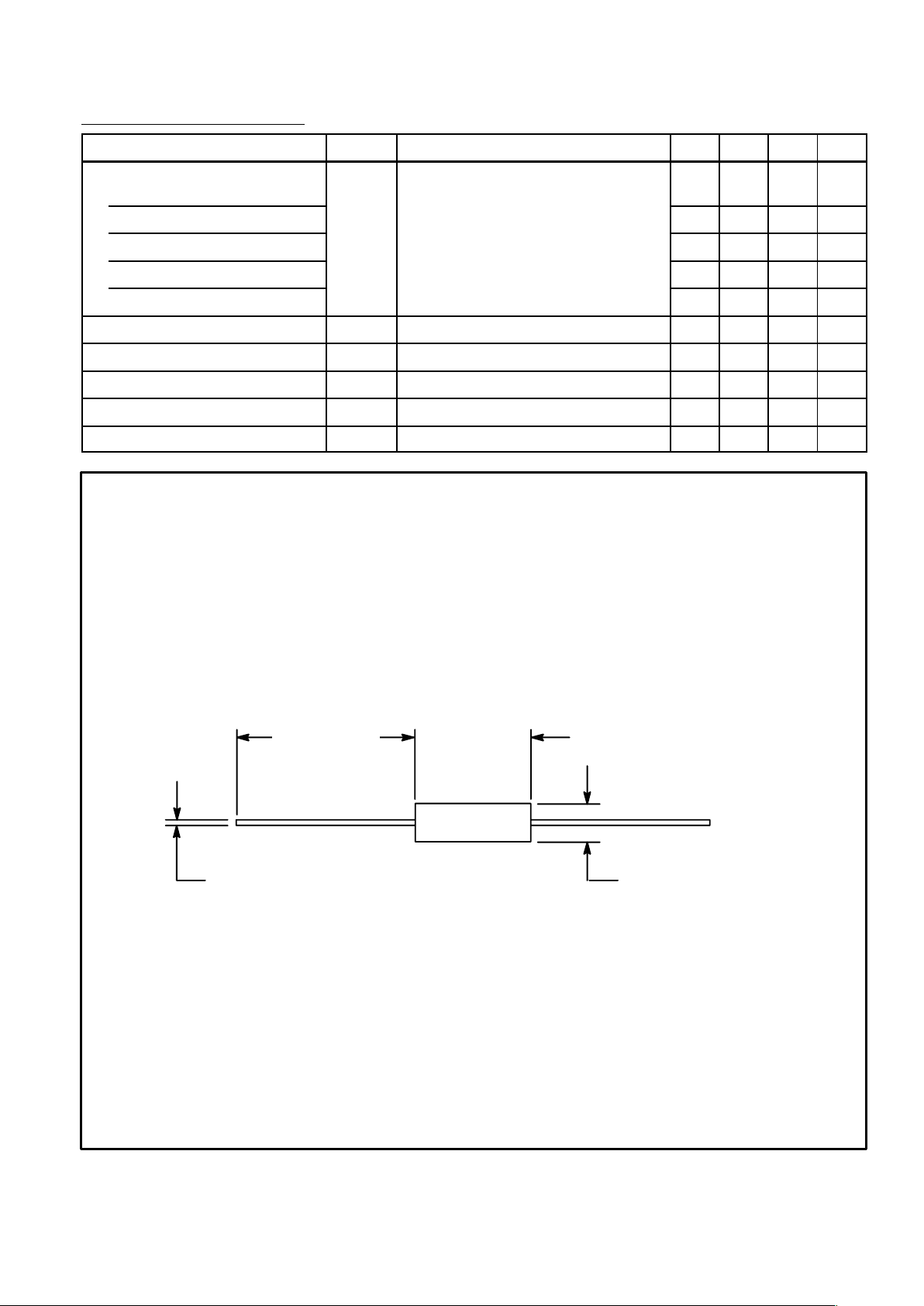
.944 (24.0)
Min
.295 (7.5)
Max
.188 (4.78)
.051 (1.29)
 Loading...