

NTE NTE6412, NTE6407, NTE6411, NTE6408 Datasheet
NTE6407, NTE6408,
NTE6411, NTE6412
Bilateral Trigger Diodes (DIACS)
Description:
The NTE6407 thru NTE6412 are bilateral trigger DIACs offering a range of voltage characteristics
from 28V to 63V. These devices are triggered from a blocking–to–conduction state for either polarity
of applied voltage whenever the amplitude of applied voltage exceeds the breakover voltage rating
of the DIAC.
Features:
D Glass–Chip Passivation
D DO35 Type Trigger Package
D Wide Voltage Range Selection
Absolute Maximum Ratings:
Maximum Trigger Firing Capacitance 0.1µF. . . . . . . . . . . . . . . . . . . . . . . . . . . . . . . . . . . . . . . . . . . . . . .
Device Dissipation (TA = –40° to +40°C), P
D
Derate Above +40°C 3.6mW/°C. . . . . . . . . . . . . . . . . . . . . . . . . . . . . . . . . . . . . . . . . . . . . . . . . . . .
Operating Junction Temperature Range, T
Storage Temperature Range, T
stg
Thermal Resistance, Junction–to–Ambient, R
Thermal Resistance, Junction–to–Lead (Note 1), R
j
thJA
thJL
Lead Temperature (During Soldering, 1/16” (1.59mm) from case, 10sec max), T
Note 1. Based on maximum lead temperature of +85°C at ≤ 250mW.
–40° to +125°C. . . . . . . . . . . . . . . . . . . . . . . . . . . . . . . . . .
–40° to +125°C. . . . . . . . . . . . . . . . . . . . . . . . . . . . . . . . . . . . . . . . . .
L
250mW. . . . . . . . . . . . . . . . . . . . . . . . . . . . . . . . . . . . . . . .
278°C/W. . . . . . . . . . . . . . . . . . . . . . . . . . . . . . . . . .
100°C/W. . . . . . . . . . . . . . . . . . . . . . . . . . . . .
+230°C. . . . . . . .
Electrical Characteristics: (TC = +25°C unless otherwise specified)
Parameter Symbol Test Conditions Min Typ Max Unit
Breakover Voltage (Forward and Reverse)
NTE6407 V
NTE6408 28 32 36 V
NTE6411 35 40 45 V
NTE6412 56 63 70 V
Breakover Voltage Symmetry
NTE6407, NTE6408 ∆V
NTE6411 – – 3 V
NTE6412 – – 4 V
BO
Note 2 – – 2 V
BO
24 28 32 V
Note 2. ∆VBO = [ |+VBO| – |–VBO| ].
Electrical Characteristics (Cont’d): (TC = +25°C unless otherwise specified)
Parameter Symbol Test Conditions Min Typ Max Unit
Dynamic Breakback Voltage
NTE6407, NTE6408 V
NTE6411 |∆V±|, Note 3 10 – – V
NTE6412 20 – – V
Peak Breakover Current I
Peak Pulse Current
NTE6407, NTE6408, NTE6411 I
NTE6412 – – 1.5 A
TRM
|∆V±|, at 10mA, Note 3 7 – – V
BB
At Breakover Voltage – – 25 µA
BO
For 10µs, 120PPs, TA ≤ +40°C – – 2.0 A
Note 3. Typical switching time is 900ns measured at IPK.
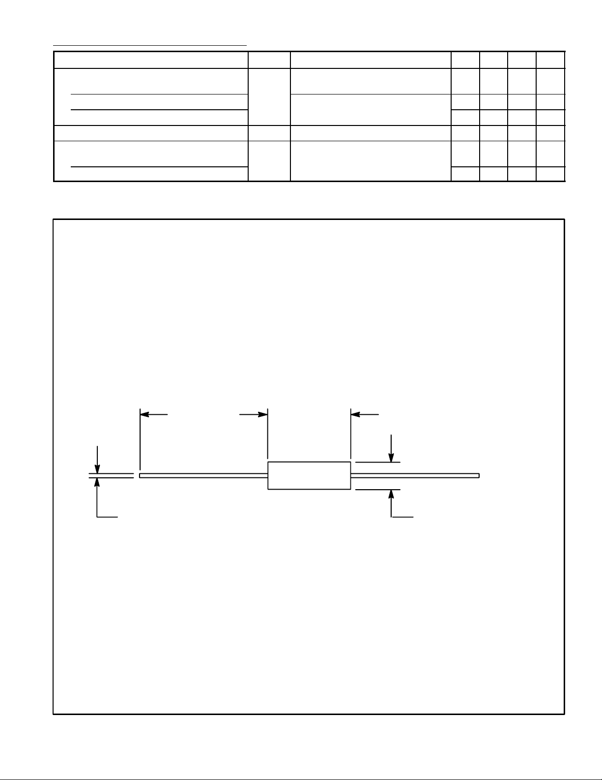
.030 (.726)
1.100 (27.9) .210 (5.33)
Max
.107 (2.73)
 Loading...