

NTE NTE6404 Datasheet
NTE6404
Silicon Unilateral Switch (SUS)
Description:
The NTE6404 is a silicon planar , monolithic integrated circuit having thyristor electrical characteristics
closely approximating those of an “ideal” four layer diode. The device is designed to switch at 8 volts
with a 0.02%/°C temperature coefficient. A gate lead is provided to eliminate rate effect, obtain triggering at lower values and to obtain transient free wave forms.
Silicon Unilateral Switches are specifically designed and characterized for use in monostable and
bistable applications where low cost is of prime importance.
Applications:
D SCR Triggers
D Frequency Dividers
D Ring Counters
D Cross Point Switching
D Over–Voltage Sensors
Absolute Maximum Ratings:
Power Dissipation (Note 1) 300mW. . . . . . . . . . . . . . . . . . . . . . . . . . . . . . . . . . . . . . . . . . . . . . . . . . . . . . .
Peak Reverse Voltage –30V. . . . . . . . . . . . . . . . . . . . . . . . . . . . . . . . . . . . . . . . . . . . . . . . . . . . . . . . . . . . .
DC Forward Anode Current (Note 1) 175mA. . . . . . . . . . . . . . . . . . . . . . . . . . . . . . . . . . . . . . . . . . . . . . .
DC Gate Current (Note 1, Note 2) 5mA. . . . . . . . . . . . . . . . . . . . . . . . . . . . . . . . . . . . . . . . . . . . . . . . . . .
Peak Recurrent Forward Current (1% duty cycle, 10µs pulse width, TA = +100°C) 1A. . . . . . . . . . .
Peak Non–Recurrent Forward Current (10µs pulse width, TA = +25°C) 5A. . . . . . . . . . . . . . . . . . . .
Operating Junction Temperature Range –55° to +125°C. . . . . . . . . . . . . . . . . . . . . . . . . . . . . . . . . . . . .
Storage Temperature Range –65° to +150°C. . . . . . . . . . . . . . . . . . . . . . . . . . . . . . . . . . . . . . . . . . . . . . .
Note 1. Derate linearly to zero at 125°C
Note 2. This rating applicable only in OFF state. Maximum gate current in conducting state limited
by maximum power rating.
Electrical Characteristics: (TA = +25°C, unless otherwise specified)
Parameter Symbol Test Conditions Min Typ Max Unit
Static Characteristics
Forward Switching Voltage V
Forward Switching Current I
Holding Current I
S
S
H
7 – 9 V
– – 200 µA
– – 0.75 mA
Electrical Characteristics (Cont’d): (TA = +25°C, unless otherwise specified)
Parameter Symbol Test Conditions Min Typ Max Unit
Static Characteristics (Cont’d)
Reverse Current I
VR = –30V, TA = +25°C – – 0.1 µA
R
VR = –30V, TA = +100°C – – 10 µA
Forward Current (Off–State) I
VF = 5V, TA = +25°C – – 0.1 µA
B
VF = 5V, TA = +25°C – – 10 µA
Forward Voltage Drop (On–State) V
Temperature Coefficient of Switching V oltage T
IF = 175mA – – 1.5 V
F
TA = –55° to +100°C – ±0.02 – %/°C
C
Dymanic Characteristics
Turn–On Time t
Turn–Off Time t
on
off
– – 1.0 µs
– – 25 µs
Capacitance C f = 1MHz – 2.5 – pF
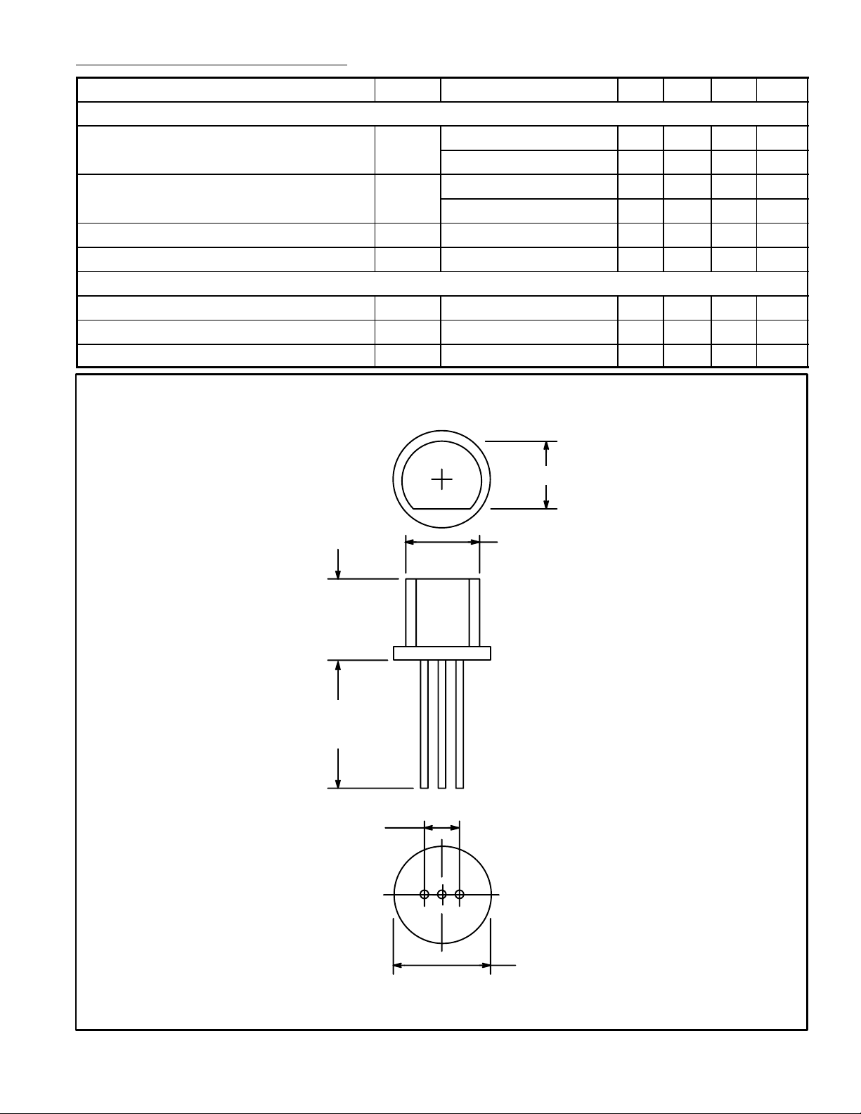
.140 (3.55) Max
.190 (4.82) Min
.265
(6.74)
Max
.500
(12.7)
Min
.100 (2.54)
A G K
.200 (5.08) Max
 Loading...