

NTE NTE6400A, NTE6400 Datasheet
NTE6400 & NTE6400A
Unijunction Transistor
Description:
The NTE6400 & NTE6400A Silicon Unijunction Transistors are three terminal devices having a stable
“N” type negative resistance characteristic over a wide temperature range. A stable peak point voltage, a low peak point current, and a high pulse pulse current make these devices useful in oscillators,
timing circuits, trigger circuits, and pulse generators where they can serve the purpose of two conventional silicon or germanium transistors.
These devices are intended for applications where circuit economy is of primary importance.
Absolute Maximum Ratings: (TA = +25°C unless otherwise specified)
RMS Power Dissipation, P
Unstabilized 450mW. . . . . . . . . . . . . . . . . . . . . . . . . . . . . . . . . . . . . . . . . . . . . . . . . . . . . . . . . . . . . .
Stabilized 600mW. . . . . . . . . . . . . . . . . . . . . . . . . . . . . . . . . . . . . . . . . . . . . . . . . . . . . . . . . . . . . . . .
Derate Above 25°C 3.9mW/°C. . . . . . . . . . . . . . . . . . . . . . . . . . . . . . . . . . . . . . . . . . . . . . . . . .
RMS Emitter Current, I
Peak Emitter Current (TJ = +150°C), I
Emitter Reverse Voltage (TJ = +150°C) 60V. . . . . . . . . . . . . . . . . . . . . . . . . . . . . . . . . . . . . . . . . . . . . . .
Interbase Voltage, V
BB
NTE6400 35V. . . . . . . . . . . . . . . . . . . . . . . . . . . . . . . . . . . . . . . . . . . . . . . . . . . . . . . . . . . . . . . . . . . .
NTE6400A 55V. . . . . . . . . . . . . . . . . . . . . . . . . . . . . . . . . . . . . . . . . . . . . . . . . . . . . . . . . . . . . . . . . .
Operating Temperature Range, T
Unstabilized –65° to +140°C. . . . . . . . . . . . . . . . . . . . . . . . . . . . . . . . . . . . . . . . . . . . . . . . . . . . . . .
Stabilized –65° to +175°C. . . . . . . . . . . . . . . . . . . . . . . . . . . . . . . . . . . . . . . . . . . . . . . . . . . . . . . . .
Storage Temperature Range, T
Thermal Resistance, Junction–to–Case, R
D
E
E(peak)
opr
stg
thJC
–65° to +175°C. . . . . . . . . . . . . . . . . . . . . . . . . . . . . . . . . . . . . . . . . .
0.16°C/mW. . . . . . . . . . . . . . . . . . . . . . . . . . . . . . . . . .
50mA. . . . . . . . . . . . . . . . . . . . . . . . . . . . . . . . . . . . . . . . . . . . . . . . . . . . . . . . . . .
2A. . . . . . . . . . . . . . . . . . . . . . . . . . . . . . . . . . . . . . . . . . . .
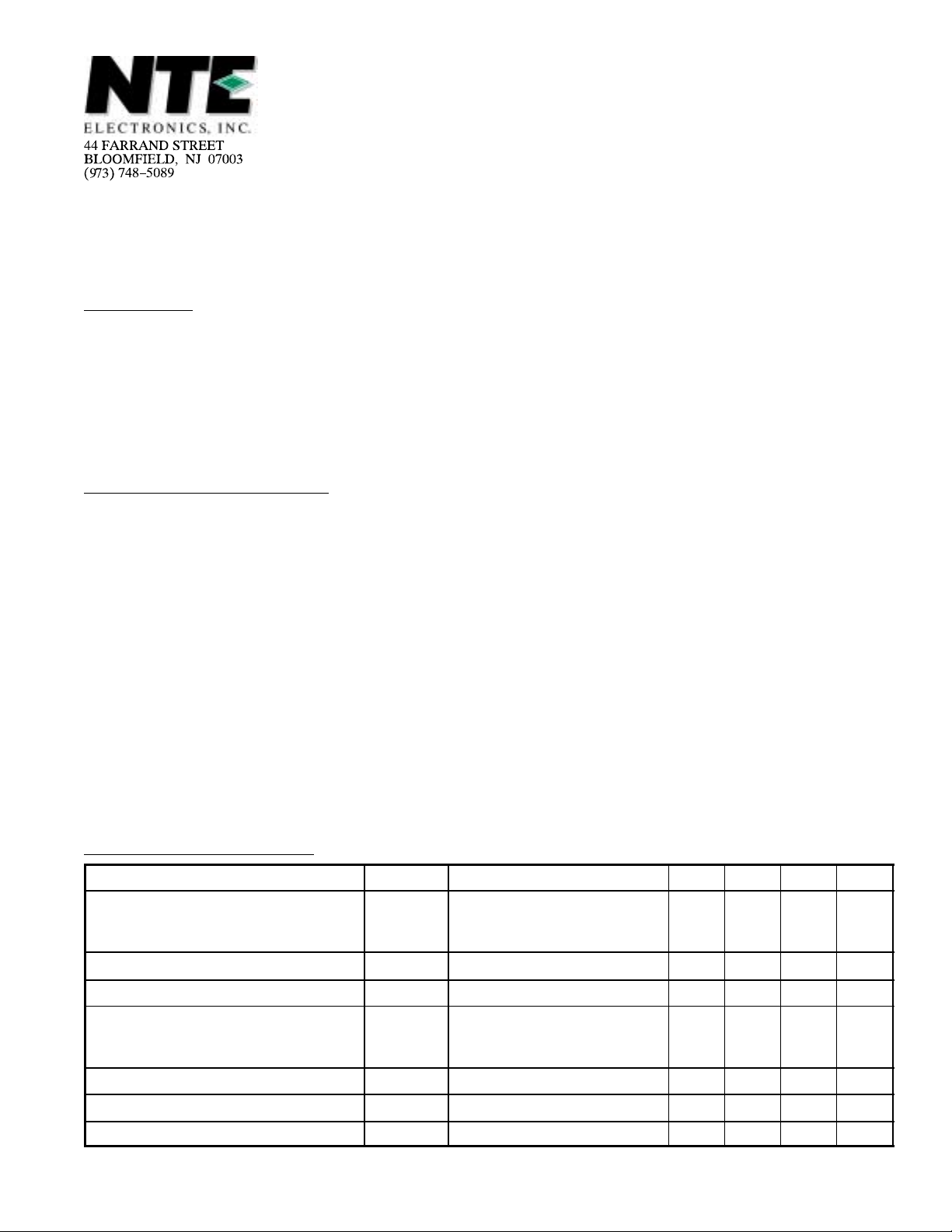
Electrical Characteristics: (TA = +25°C unless otherwise specified)
Parameter Symbol Test Conditions Min Typ Max Unit
Intrinsic Standoff Ratio
NTE6400
NTE6400A
Interbase Resistance R
Modulated Interbase Current I
Emitter Reverse Current
NTE6400
NTE6400A
Peak Point Emitter Current I
Valley Point Current I
Base–One Peak Pulse Voltage V
η VBB = 10V, Note 1
BBO
B2(MOD)VBB
I
EO
P
V
OB1
VBB = 3V, IE = 0, Note 1 4 – 12
= 10V, IE = 50mA 6.8 – 30 mA
V
= 30V, IB1 = 0
B2E
VBB = 25V – – 25 µA
VBB = 20V, RB2 = 100Ω
0.4
54
–
–
8 – – mA
3 – – V
–
0.80
–
0.67
–
–
12
1
kΩ
µA
Note 1. The intristic standoff ratio, η, is essentially constant with temperature and interbase volt-
age. It is defined by the following equation:
VP = η VBB +
200
T
j
Where VP= Peak point emitter voltage
VBB= Interbase voltage
Tj= Junction Temperature (Degrees Kelvin)
Note 2. The interbase resistance is nearly ohmic and increases with temperature in a well–defined
manner. The temperature coefficient at +25°C is approximately 0.8%/°C.
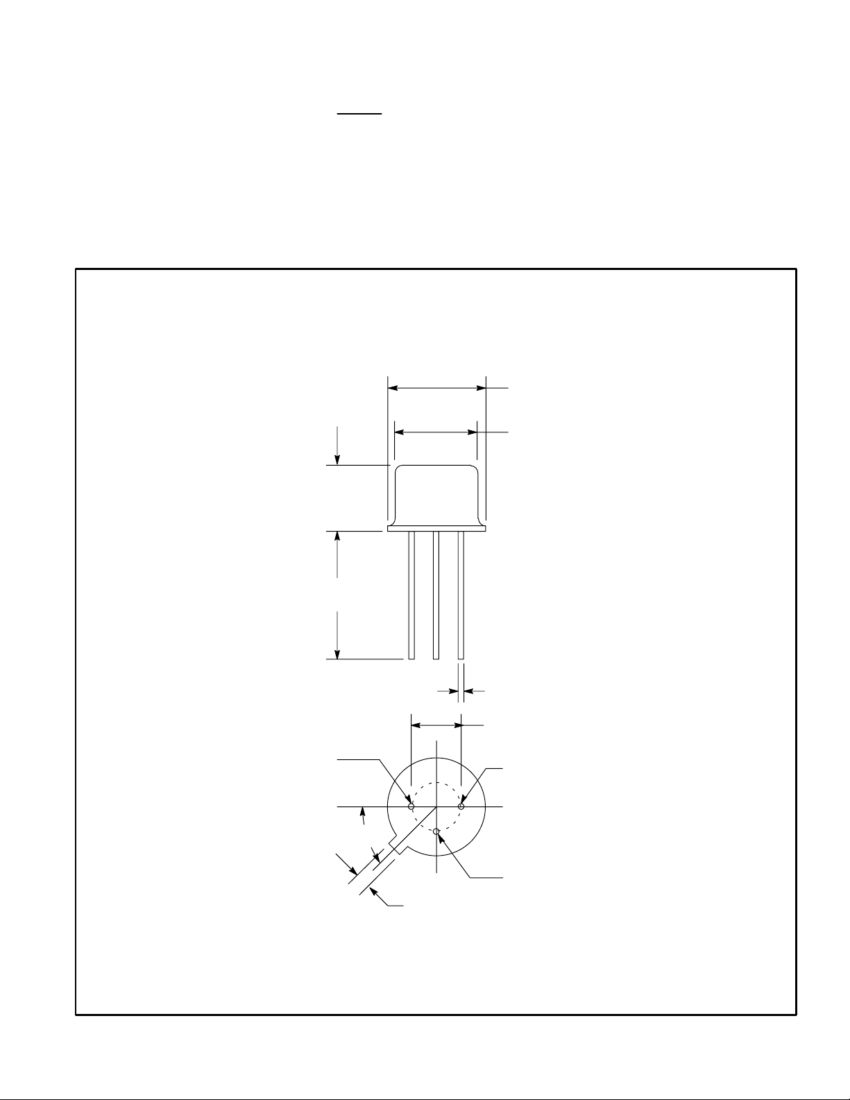
.370 (9.39) Dia Max
.355 (9.03) Dia Max
.260 (6.6)
Max
.500 (12.7)
Min
B2
45°
.018 (0.45) Dia
.210 (5.33) Dia Max
B1
Emitter
.031 (.793)
 Loading...